UNIVERSITI TEKNIKAL MALAYSIA MELAKA
THE EFFECT OF PRIMARY RELIEF ANGLE
TO THE DIMENSIONAL SURFACE ERROR
OF THIN-WALL COMPONENTS
2012
NERMIE BINTI DICKSON
UNIVERSITI TEKNIKAL MALAYSIA MELAKA
THE EFFECT OF PRIMARY RELIEF ANGLE
TO THE DIMENSIONAL SURFACE ERROR
OF THIN-WALL COMPONENTS
This report submitted in accordance with requirement of the Universiti Teknikal Malaysia Melaka (UTeM) for the Bachelor Degree of Manufacturing Engineering
(Manufacturing Process) (Hons.)
by
NERMIE BINTI DICKSON B050810001
891022-12-5528
UNIVERSITI TEKNIKAL MALAYSIA MELAKA
BORANG PENGESAHAN STATUS LAPORAN PROJEK SARJANA MUDA
TAJUK: The Effect of Primary Relief Angle to the Dimensional Surface error of Thin-wall Components
SESI PENGAJIAN: 2011/12 Semester 2
Saya NERMIE BINTI DICKSON
mengaku membenarkan Laporan PSM ini disimpan di Perpustakaan Universiti Teknikal Malaysia Melaka (UTeM) dengan syarat-syarat kegunaan seperti berikut: 1. Laporan PSM adalah hak milik Universiti Teknikal Malaysia Melaka dan penulis. 2. Perpustakaan Universiti Teknikal Malaysia Melaka dibenarkan membuat salinan
I hereby, declared this report entitled “The Effect of Primary Relief Angle to the Dimensional Surface Error of Thin-wall Components” is the results of my own
research except as cited in references.
Signature : ……….
Author’s Name : Nermie Binti Dickson
Date : 31.5.2012
APPROVAL
This report is submitted to the Faculty of Manufacturing Engineering of UTeM as a partial fulfillment of the requirements for the degree of Bachelor of Manufacturing Engineering (Manufacturing Process) (Hons.). The member of the supervisory is as follow:
i Pengisaran sisi untuk komponen yang sangat fleksibel adalah proses pembuatan yang biasa digunakan dalam industri angkasa lepas. Banyak komponen yang digunakan dalam industri angkasa lepas biasanya berstruktur dinding nipis yang sangat fleksible. Struktur yang berdinding nipis adalah tidak kukuh menyebabkan ia mudah terpesong disebabkan oleh daya pemotongan semasa operasi pengisaran sisi. Pemesongan mata alat dan bahan kerja membawa kepada kesilapan dimensi permukaan yang sangat tidak diingini. Biasanya, terdapat perbezaan yang sangat ketara antara profil perancangan dan hasil mesinan yang menyebabkan hasil mesinan tidak dapat melakukan fungsi asal yang telah ditetapkan. Geometri mata alat adalah salah satu faktor yang perlu diambil kira untuk mendapatkan hasil kisaran sisi yang berkualiti tinggi. Sudut relif primer merupakan antara geometri mata alat yang mesti diambil kira untuk mendapatkan prestasi pemotongan yang tinggi. Projek ini mengkaji tentang sudut relif primer terhadap kesilapan dimensi permukaan struktur berdinding nipis dalam pengisaran sisi. Di samping itu, daya pemotongan dan kekasaran permukaan yang telah dikisar juga turut dikaji. Hasil kajian menunjukkan sudut relif primer memberi kesan yang ketara kepada kesilapan dimensi permukaan bagi komponen yang berdinding nipis di mana sudut relief primer yang lebih kecil memhasilkan kesilapan dimensi yang lebih rendah.
ii Peripheral milling of very flexible components is a common manufacturing process in the aerospace industry. Many components used in the aerospace industry are usually thin-walled structures which is very flexible. Thin-walled structures are not rigid hence easily deflect due to cutting force during peripheral milling operation. The tool-workpiece deflection results in significant dimensional surface error which is highly undesirable. There is usually a significant deviation between the planned and machined part profiles that the machined parts may no longer be able to serve its original designated functionality. The geometry of cutting tool is one of the factors that must be considered in obtaining high quality milling. Primary relief angle is one of significant tool geometry that must be considered to obtain high cutting performance. This research studies on the effects of primary relief angle of endmill on the dimensional surface error of peripheral milling of thin-walled structure. Besides, the cutting force and surface roughness of the milled thin wall also investigated. The results obtained show that primary relief angle has significant effect to the dimensional surface error of thin-wall components where smaller primary relief angle has lower surface error.
iii This thesis is dedicated to all the people who never stop believing in me
my beloved parents my brothers
my friends
iv First and foremost I would like to thank God for giving me the power to complete this report. I could never have done this without Your help. I love You.
I wish to express my sincere appreciation to my supervisor, Dr Raja Izamshah B. Raja Abdullah for his supervision and support that truly help the progression and completion of this project. You are the best supervisor ever.
I would like to thank UTeM for giving me a golden opportunity to do research along with good machinery and skilled staffs. Special thanks to Mohd Hanafiah bin Mohd Isa for his endless help in handling milling machine and Muhammad Helmi bin Kahar for the cutting tool fabrication.
Special thanks to my family especially my parents for their never ending long distance love and support. They will always be my inspiration.
From the bottom of my heart, I really want to thank my coursemate, Nurul Fatin Bt Mohamad Raffi for her uncountable help in completing this project. Thank you so much, it is very kind of you. God bless you.
Last but not least, thank you to my beloved friends and all the people that have helped me in this project.
v
2.2 Force-induced Deflection in Peripheral Milling of Thin-wall 7
vii
2.1 Mechanical Properties of Aluminium Alloy 7075 15
2.2 The characteristics of the carbide endmill tool studied by 16 De’pince and Hascoet (2006)
2.3 Cutting Conditions for the Peripheral Milling Experiments by 17 Tsai and Liao, (1990)
3.1 Recommended Relief Angle on Endmills (YG-1 Co., LTD) 21 3.2 Recommended Tool Geometry (Bangalore, 1980) 21 3.3 The Primary and Secondary Relief Angle of Endmill for Research 22
3.4 The Characteristics of Endmill 23
3.5 Machining Parameter for Milling of Thin-wall 28
4.1 The Workpiece and Its Corresponding Tools 35 4.2 Machining Conditions for the Peripheral Milling Experiments for 36 Both Machining From 6mm to 4mm and From 4mm to 2mm
4.3 The Maximum Cutting Force 47 4.4 Surface Roughness of Thin-Wall after Machining from 6mm to 4mm 48 4.5 Surface Roughness of Thin-Wall after Machining from 4mm to 2mm 48
viii
1.1 Surface Dimensional Error in Thin-wall 3
1.2 The Desired Surface Finish 3
2.1 The Peripheral Down Milling of Thin-walled Workpiece 6
xi
N - Rotational speed
α2 - Secondary Relief Angle
N - Teeth number
3D - 3 Dimensional
1 This section introduces the background of the peripheral milling of thin-wall workpiece, the problem statement of the research, the research objectives and the research scope.
1.1 Background
Thin-wall milling is important in machining of aerospace components. Machining a complex part with many thin sections from a single, monolithic workpiece can be dramatically less expensive than building up the part via traditional fabrication techniques. Thin-wall machining can be a way to increase both productivity and profitability compared with fabricating thin walls. Subjected to the forces generated by metal removal, a thin-wall’s relatively delicate structure will move relative to the tool, making it difficult to maintain dimensional accuracy and impart the specified surface finish (Kennedy, 2007).
Nowadays, many thin-wall structure parts, which traditionally were assembled from simpler parts, are being machined from a unique starting raw block material to their final shape. For this purpose, it is necessary to remove up to 95 percent of the material, resulting in airframe parts known as monolithic structure parts. These parts present enhanced homogeneity and physical properties. However, removing large amount of materials usually results in large warping or distortion due to the re-establishment of equilibrium in the retained part along with the relief of the initial residual stresses in the removed part. In many cases, these warping or distortions can
2 be so large that the machined parts may no longer be able to serve its original designated functionality.
Most open literatures studying on monolithic component deformations focused on the prediction of surface dimensional errors induced by machining loads and clamping forces. This kind of machining error belongs to local elastic deformation. Controlling the local elastic deformation can improve the machining precision of local features, such as marginal plate and web plate. However, even if the surface dimensional error meets the design criterion, the monolithic component will
inevitably be discarded for the large overall warping or distortion (Bai et.al., 2010).
1.2 Problem Statement
3 Figure 1.1: Surface Dimensional Error in Thin-wall
4
1.3 Research Objectives
Most of the existing research on machining thin-wall component concentrated on the process planning, little attention is emphasized on the effect of cutting tool on the occurrence of the surface error and surface roughness. Driven by the need to constantly increase the machining efficiency and part accuracy, the objectives of this project are:
a) to investigate the effect of primary relief angle on the dimensional surface error when milling thin-wall workpiece.
b) to investigate the effect of primary relief angle on the cutting force when milling thin-wall workpiece
c) to investigate the effect of primary relief angle on the surface roughness when milling thin-wall workpiece.
1.4 Research Scope
5
This section discusses about the reviews from previous literatures and researches regarding the surface dimensional error in thin-wall milling. This section also include the cutting tool parameter especially the relief angle, the force that cause deflection in thin wall and the peripheral milling of thin-wall aluminium alloy.
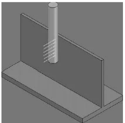
2.1 Peripheral Milling of Thin-wall
In peripheral milling, the milled surface is generated by teeth located on the periphery of the cutter body. The axis of cutter (endmill) rotation is parallel to the workpiece surface (Kalpakjian, 2006). Peripheral milling of very flexible components is a common manufacturing process in the aerospace industry. Very flexible components are considered to have a wall thickness thinner than 5 mm and an axial depth of cut larger than 30 mm. The wall thickness of the component is reduced further by peripheral milling operation using a long, helical slender end mill. A typical example for the process is peripheral milling of jet engine impellers and rotor discs on five axis CNC machining centers (Budak and Altintas, 1995).
6
Figure 2.1: The Peripheral Down Milling of Thin-wall Workpiece (Budak and Altintas, 1995)
(a) (b)
Figure 2.2: (a) Conventional-“Up” Milling and (b) Climb-“Down” Milling (Source: Kalpakjian, 2006)
7
2.2 Force-induced Deflection in Peripheral Milling of Thin-wall
The peripheral milling of thin-wall is complicated, where periodically varying milling forces excite the flexible cutter and plate structures both statically and dynamically. Static deflections produce dimensional form errors, and dynamic displacements produce poor surface finish in milling (Budak and Atlantis, 1995). Very flexible plates are considered to have a large span ratio of height to thickness. The part to be machined discussed in this paper is only limited to the small deformations of thin-walled plates. In peripheral milling of the thin-walled plates, the radial forces can be looked as the linear loads (see Figure 2.3). The thin-walled plates in Figure 2.3 can be considered as the cantilever plate, which is also the boundary condition for the plate. For simplification, it applies the following assumptions for the calculation of small deformations of thin-walled plates:
a) The displacement of every point on the plates does not change along the thickness, which is equal to the deformations of the plate middle plane.
b) Straight normal line hypothesis: the normal line is still straight and vertical to the middle plane both pre deformations and after deformations.
c) The normal stress applied on the plane that is parallel to the middle plane is very small. It thus can be ignored.
(Tang and Liu, 2008)
8
2.3 Current Research on Milling of Thin-wall
Most of the studies and researches have been made are more on the prediction of surface dimensional error in the thin-wall milling. There is still no research on the study of cutting tool geometry in reducing the surface dimensional error in thin-wall milling especially the study on the relief angle on the dimensional error. Many researches use FEA method to simulate the thin-wall milling which is complicated and time-consuming.
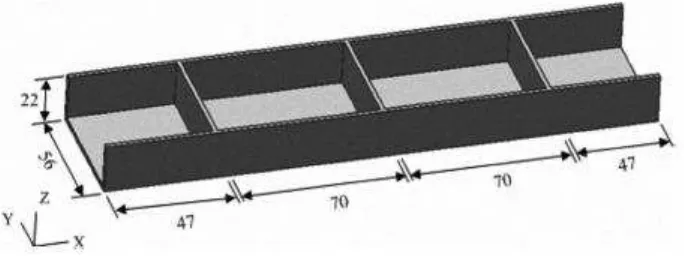
In Bai et. al. (2010) study, a finite element analysis (FEA) based milling process simulation system was developed to predict machining deformation of aerospace thin-walled monolithic structures. Some key factors such as initial residual stress, cutting loads, cutting sequence and tool path were introduced synthetically into the simulation system. The geometry of workpiece that Bai et. al studied is shown in Figure 2.4. All the thicknesses of the side wall, rib plate and web plate are equal to 2mm.
Figure 2.4: The Thin-walled Structure Studied by Bai et. al. (2010)