UNIVERSITI TEKNIKAL MALAYSIA MELAKA
Study the Effect of Wire-EDM Parameters on
Surface Roughness for Machining Die-Steel
Thesis submitted in accordance with the requirements of the Universiti Teknikal Malaysia Melaka for the Bachelor Degree of Manufacturing Engineering in
Manufacturing Process ( Honours ).
By
Mohd Syafiq Bin Dzulkapli
UTeM Library (Pind.1/2007)
√
√
BORANG PENGESAHAN STATUS TESIS*
UNIVERSITI TEKNIKAL MALAYSIA MELAKA
JUDUL:
SESI PENGAJIAN: 2007/ 2008
Saya _____________________________________________________________________
mengaku membenarkan t esis (PSM/ Sarj ana/ Dokt or Falsaf ah) ini disimpan di Perpust akaan Universit i Teknikal Malaysia Melaka (UTeM) dengan syarat -syarat kegunaan sepert i berikut :
1. Tesis adalah hak milik Universit i Teknikal Malaysia Melaka.
2. Perpust akaan Universit i Teknikal Malaysia Melaka dibenarkan membuat salinan unt uk t uj uan pengaj ian sahaj a.
3. Perpust akaan dibenarkan membuat salinan t esis ini sebagai bahan pert ukaran ant ara inst it usi pengaj ian t inggi.
4. **Sila t andakan (√)
STUDY THE EFFECT OF WIRE-EDM PARAMETERS ON SURFACE ROUGHNESS FOR MACHINING DIE-STEEL
MOHD SYAFIQ BIN DZULKAPLI
Disahkan ol eh:
* Tesis dimaksudkan sebagai t esis bagi Ij azah Dokt or Falsaf ah dan Sarj ana secara penyelidikan, at au disert asi bagi pengaj ian secara kerj a kursus dan penyelidikan, at au Laporan Proj ek Sarj ana Muda (PSM).
(Mengandungi maklumat TERHAD yang t elah dit ent ukan oleh organisasi/ badan di mana penyelidikan dij alankan) (Mengandungi maklumat yang berdarj ah keselamat an at au kepent ingan Mal aysia yang t ermakt ub di dalam AKTA RAHSIA RASMI 1972)
TIDAK TERHAD TERHAD
√
DECLARATION
I hereby, declared this thesis entitled “Study the Effect of Wire-EDM Parameters on Surfaces Roughness for Machining Die-Steel” is the result of my own research except as cited in references.
Signature : ………. Author’ s Name : MOHD SYAFIQ BIN DZULKAPLI
APPROVAL
This thesis submitted to the senate of UTeM and has been accepted as partial fulfilment of the requirements for the degree of Bachelor of Manufacturing (Manufacturing Process) wit Honours. The members of the supervisory committee
are as follow:
ABSTRACT
ABSTRAK
DEDICATION
ACKNOWLEDGEMENTS
I would like to thanks to my parent for giving me a support and encouragement to finish this thesis in partial fulfillment for Bachelor of Manufacturing Engineering (Process )
As appreciation and great helpful I had received during completing this thesis, I would like to dedicate my thankfulness to my supervisor Pn Rosidah Bt Jaafar for PSM 1 and Dr Mohd Rizal Salleh for PSM 2 for his supervision and guidance to finish this thesis. I would like to acknowledge (EDM) laboratory technicians, who have been so warmth and kind to provide sincere assistance and good cooperation during the training period. Also not to forget to the Mr Sharul as my second
evaluator, Mr Hadzley our Head of FKP department and all FKP lectures that giving help to finish this thesis.
TABLE OF CONTENTS
List of Figure ... viii
List of Table...x
List of Abbreviation, Symbols, Specialized Nomenclature ... xi
1. INTRODUCTION... 1
1.1 Background... 1
1.2 Problem Statements ... 2
1.3 Objectives ... 3
1.4 Scopes of the Project... 3
2. LITERATURE REVIEW... 4
2.1 Electric Discharge Machine (EDM) ... 4
2.1.1 Spark generator ... 6
2.1.2 Servo System ... 7
2.1.3 Dielectric system... 7
2.1.4 Mechanical Structure ... 8
2.2 Material Removal Mechanism... 8
2.2.1 Breakdown (Ignition) Phase ... 9
2.2.2 Discharge Phase... 10
2.2.3 Erosion (Crater Formation) Phase ... 10
2.3 Basic principle of Electrical Discharge Machining (EDM)... 11
2.4 Wire Electrical Discharge Machine (Wire EDM) ... 13
2.4.1 Introduction... 13
2.4.3 The Principle of Wire Electrical Discharge Machine (Wire EDM) ... 16
2.6 Surface Metrology. ... 24
2.6.1 Surface evaluation... 25
2.6.2 Surface texture ... 25
2.6.3 Surface roughness ... 26
2.6.4 Surface roughness factor on Wire EDM ... 29
2.6.5 Characteristic of EDM surfaces... 30
2.7 Design of Experiment (DOE). ... 32
2.7.1 DOE overview ... 32
2.7.2 Two Level Factorial Design ... 32
3. METHODOLOGY... 34
3.1 Introduction... 34
3.2 Selection machines and material... 35
3.2.1 Wire EDM... 35
3.2.2 Portable Surface Roughness Tester ... 38
3.2.3 Material... 39
3.2.4 Wire Electrode ... 39
3.3 Profile Design and Drawing ... 40
3.4 Identify the method of DOE ... 40
3.4.1 Two Level Factorial Design and Minitab software ... 40
3.5 Parameters... 41
3.6 Conduct of experiment- machining using wire EDM... 42
3.6.2 Metallurgy Microscope... 43
3.7 Data collection and analysis ... 44
4. RESULTS... 45
4.1 Surface Roughness Data ... 45
4.2 Factorial Design Analysis ... 49
4.3 Reduced Model ... 52
4.4 Surface Texture... 53
5. DISCUSSION...55
6. CONCLUSSION AND RECOMENDATION... 57
6.1 Conclussion... 57
6.2 Recommendation ... 58
REFERENCES... 59
APPENDICES
A. Gant chart for PSM1 A Gant chart for PSM2 B Profile drawing
LIST OF FIGURES
2.1 Basic Elements of an EDM system. 6
2.2 Evolution of a single spark in the EDM process 12
2.3 wire EDM machine. 14
2.4 Schematic of wire-EDM system 16
2.5 Basic principle of wire 17
2.6 A schematic diagram of wire rotation in wire EDM operation 21
2.7 AISI D2 die steel compositions 23
2.8 Coefficient of Thermal Expansion (x10-6/C°) 23 2.9 Standard terminology and symbol to describe surface finish. The
quantities are given in µin
25
2.10 The Arimethic mean value 27
2.11 Coordinate used for surface roughness measurement 28 2.12 ISO-Recommended Roughness Values and Grade
Numbers for the specification of surface roughness
39
3.1 Flow chart for overall project 35
3.2 Mitsubishi wire EDM machine RA 90 series 36 3.3 Mitutoyo Portable surface roughness (SJ 301) 38
3.4 EDM brass cutting wire electrode. 39
3.5 Technical drawing for profile design. 40 3.6
Calibration process using Mitutoyo Portable Surface Roughness Metallurgy Microscope
Surface Roughness (Ra) versus IP and Off Time (OFF) Surface Roughness (Ra) versus Voltage Open (Vo) Surface Roughness (Ra) versus Off Time ( OFF) Normal probability plot of the effects
4.5 4.6 4.7
Interaction Plot (data means) for Surface Roughness (Ra) Main Effects Plot (data means) for Surface Roughness (Ra ) Pareto Chart of the Effects
LIST OF TABLES
2.1 Basic types of tool and die steel 22
3.1 Machine specification 36
3.2 Total of the experiment test 41
3.3
4.1 4.2
Values of each parameter
Surface roughness value for material die steel. Surface texture results
41
CHAPTER 1
INTRODUCTION
1.1 Background
The development in manufacturing machining have create new era to the many
industrial such as automotive, aerospace and other industrial that need precision in
their products. The new machines have introduced to change the old conventional
method in machining process. The ability of this machine also improves because of
the requirement in many industries that need accuracy and reduce machine time.
Accompanying the development of mechanical industry, the demands for alloy
materials having high hardness, toughness and impact resistance are increasing. One
of those technological developments is novel materials for making various kinds of
dies. New die steels have been continuously introduced to the die manufacturers,
and affect their die-making processes or their die quality (Boonmung and
Kanlayasari, 2007). Nevertheless, those materials are difficult to be machined by
traditional machining methods. Hence, non-traditional machining methods including
electrolytic grinding, supersonic machining and electrical discharging machining
(EDM) are applied.
EDM is one of the unconventional machine develop from the previous conventional
machine like milling. EDM is the precision manufacturing machining processes
available for creating complex or simple shapes and geometries within parts and
Wire-EDM uses electro-thermal mechanisms to cut electrically conductive material.
The material is removed by a series of discrete discharges between the wire electrode
and the workpiece in the presence of a dielectric fluid, which creates a path for each
discharge as the fluid becomes ionized in the gap. The region in which discharge
occurs is heated to extremely high temperatures, so that the work surface is melted
and removed.
There are many parameter and variables that influence the EDM operation. The
parameters that were used influenced the result of the surface roughness. The
parameters which influence surface roughness arepulse-on time (ON), pulse-off time
(OFF), pulse-peak current (Ip), and wire tension (WT), cutting tool and material of
workpiece
The research of this paperwork is to study the wire EDM machining process
performance In this paperwork will be focuses on the effect of wire EDM parameters
on the surface roughness for machining die steel. The several parameters stated will
be study to analyzed machining performance in surface roughness. The evaluations
are defined from the experiment outcomes.
1.2 Problem Statement
The wire EDM machining is the most accurate manufacturing process. But there are
a few problems that need to be highlighted. The selection of cutting parameters for
obtaining higher cutting efficiency or accuracy in wire-EDM is still not fully solved.
This is because due to the complicated stochastic process mechanisms in wire-EDM.
AISI D2 is new material use in wire EDM machining process in UTeM, so the
1.3 Objectives:
1. To study the effect of wire-EDM parameters on surface roughness for
machining die steel by conducting several machining process.
2. To evaluate the quality of the surface roughness produce by different
EDM parameters using surface roughness tester.
3. To find the derivative parameters that affects the EDM surface roughness.
1.4 Scope of the Project
The scope of this project is conducting a machining operation using wire EDM to
analyze the machining performance. The machining operation is using Mitsubishi
RA 90 series wire EDM. This study will be focused on the effect of the working
surface. The parameter such as voltage open, pulse off time and pulse peak current
will be set according to the design of experiment (DOE) and the other parameters
remain constant. The material tested is AISI D2 high carbon and the electrode is
brass wire diameter 0.25mm will be use during the experiment. After the machining
operation, the surface of cutting material will analyzed using surface roughness
tester. The surface roughness tester using is Portable Surface Roughness Tester (SJ
301). Then from the result obtained, the comparison of the surface roughness
CHAPTER 2
LITERATURE REVIEW
2.1 Electrical Discharge Machine (EDM).
The beginning of EDM came during the Second World War, when two Russian
physicists B.R. and N.I. Lazarenko published their study on The Inversion of the
Electric Discharge Wear Effect which related to the application to manufacturing
technology of the capacity of electrical discharges, under controlled distribution, to
remove metal.
EDM was being used at that time to remove broken taps and drills. The early
“Tap-Busters” disintegrated taps with hand fed electrodes, burning a hole in the center of
the tap or drill, leaving the remaining fragments that could be picked out. This saved
workpieces and very expensive parts from being scrapped and re-made. This process
opened the birth of Vertical EDM, also called: Sinker, Conventional, Ram, Plunge or
Diesinker EDM, because the burned downward in the Z-axis. These machines were,
and still are primarily used to make precision cavities in metal for the mold
industry.(kalpakjian, S and Schmid, S.R, 2000)
The recent increase in the use of hard, high strength, and temperature resistant
materials in engineering has made it necessary to develop many machining
techniques. With the exception of grinding, conventional method of removing
material from a workpiece are not readily applicable to most of these new materials.
Most of the new machining processes have been developed specifically for materials
complex shapes and cavities in softer, more readily machined material. The EDM is
one of unconventional method that use in machining process as the development in
manufacturing technology.
Basically Electric Discharge Machining (EDM) is a process for eroding and
removing material by transient action of electric sparks on electrically conductive
materials. This process is achieved by applying consecutive spark discharges
between charged workpiece and electrode immersed in a dielectric liquid and
separated by a small gap. Usually, localized breakdown of the dielectric liquid occurs
where the local electrical field is highest. Each spark melts and even evaporates a
small amount of material from both electrode and workpiece. Part of this material is
removed by the dielectric fluid and the remaining part resolidifies rapidly on the
surfaces of the electrodes. The net result is that each discharge leaves a small crater
on both workpiece and electrode. Application of consecutive pulses with high
frequencies together with the forward movement of the tool electrode towards the
workpiece, results with a form of a complementary shape of the electrode on the
workpiece.
The material removal rate, electrode wear, surface finish, dimensional accuracy,
surface hardness and texture and cracking depend on the size and morphology of the
craters formed. The applied current, voltage and pulse duration, thermal
conductivity, electrical resistivity, specific heat, melting temperature of the electrode
and workpiece, size and composition of the debris in dielectric liquid can be
considered as the main physical parameters effecting to the process. Among them,
applied current, voltage and pulse duration are the parameters which can be
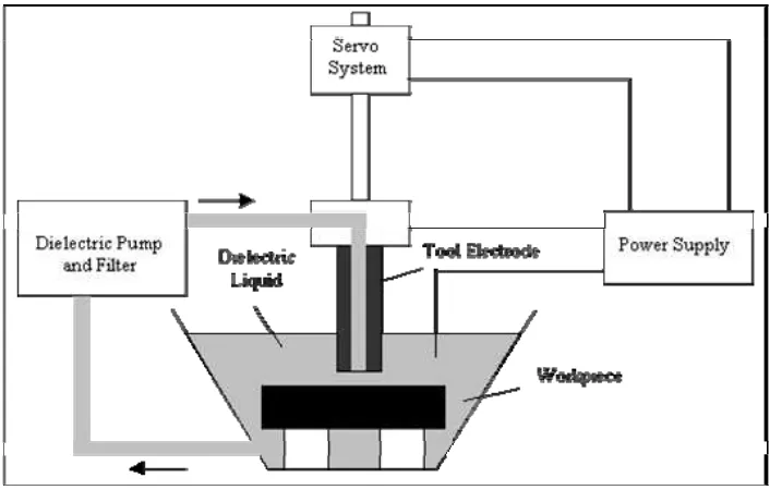
Figure 2.1. Basic elements of an EDM system. (Nedians., Fortunecity, 2007)
Every EDM machine has the following basic elements as shown in Figure 2.1.
1. Spark generator
2. Servo system
3. Dielectric liquid
4. Mechanical structure
2.1.1 Spark Generator .
The required energy is in the form of pulses usually in rectangular form. Recent
studies have been shown that application of pulses in the form of trapezoids resulted
with a marked improvement in cutting efficiency. The optimum pulse form is not
exactly a trapezoid, but similar.
Electrical energy in the form of shot duration impulses with a desired shape should
be supplied to the machining gap. For this purpose, spark generators are used as the
the way in which the voltage is transformed and the pulse is controlled. The
discharge may be produced in a controlled manner by natural ignition and relaxation,
or by means of a controllable semiconductor switching elements. Nowadays,
sophisticated computer aided spark generators are in use as a result of fast
development in electronics industry. These types of generators give us a better
manner in controlling physical parameters.
2.1.2 Servo System.
Both electrode and workpiece are eroded during the process, after a certain time
dimensions of the electrodes will be changed considerably. The result is increase in
interelectrode gap. This will increase the voltage required for sparking. This problem
can be solved by increasing the pulse voltage or decreasing the gap distance. The
former is not feasible since most of the electrical energy is used for overcoming
breaking strength and producing plasma in dielectric liquid rather than machining, in
addition to that, the required voltage can increase to the levels that spark generator
can not supply, therefore; the interelectrode gap should be maintained constant
during the process. This can be achieved by a servo system which maintains a
movement of the electrode towards the workpiece at such a speed that the working
gap, and hence, the sparking voltage remains unaltered.
2.1.3 Dielectric Circuit.
High cooling rates during resolidification process changes the chemical composition
of the both electrodes and dielectric liquid machining particles called debris are
formed. Formation of such particles effects on machining performance, therefore,
dielectric liquid should be circulated to prevent contamination in working gap. This
circulation is done by a dielectric circuit which is composed of a pump, filter, tank
2.1.4 Mechanical Structure.
EDM machines have similar construction with conventional drilling and milling
machine frames with vertical tool feeding and horizontal worktable movements.
Since there is not a real contact between electrodes, that’s why, it is considered that,
the frame elements not taking much force as in conventional machining so simpler
design is possible. This consideration needs a little bit attention, because gas bubbles
collapses at the end of discharge and cause high frontal shock waves, therefore; the
frame should be strong enough to keep its dimensional stability. (Nedians.,
Fortunecity, 2007)
2.2 Material Removal Mechanism.
A perfect general theory for EDM can not constructed since each machining
condition has its own particular aspects and involves numerous phenomena, i.e., heat
conduction and radiation, phase changes, electrical forces, bubble formation and
collapse, rapid solidification. In addition, theories of how sparks eroded the
workpiece and electrode have never been completely supported by the experimental
evidence since it’s very difficult to observe the process scientifically. Thus, most of
the published studies are mostly concerned with simplified models of different events
of EDM. Development of high-speed computers and comprehensive numerical
techniques enabled scientist to involve more parameters in their models than before,
but still many aspects of the process can not be explained in detail.
Melting, vaporization and even ionization of the electrode materials occurs at the
point where the discharge takes place. Flushing action of the dielectric liquid pulls
away whole vaporized and some of melted material. The result is formation of a
crater on both electrode surfaces. Theoretical models based on one spark can be
extended to the machining with same side effects. Generally the physics of the sparks
can be investigated in three phases.
(ii) Discharge phase
(iii) Erosion(Crater Formation) phase
Breakdown phase takes a relatively small percent of the total spark time. It varies
from few microseconds to several hundreds depending on discharge conditions.
Erosion is only observed only in later stages of spark, partly after the discharge has
eased.
2.2.1 Breakdown (Ignition) Phase.
Breakdown in liquids is the initial condition for plasma formation. There are several
proposed theories which try to explain the breakdown phase, but consistent results
with experiments can not be obtained. A simplified expression can be given as
below.
The charge induced on the two electrodes by the power supply creates a strong
electric field. This field is strongest where the electrodes are closest to each other.
This is the point where discharge takes place. Molecules and ions of the dielectric
fluid are polarized and oriented between these two peaks and forming a narrow,
low-resistance channel. When the dielectric strength of the liquid in the gap exceeded due
to the electric field, breakdown occurs. Electrons emitted from both electrodes and
the stray electrons and ions in the dielectric liquid are accelerated. When accelerated
electrons and ions reached to the electrons a current flow starts which is the
beginning of the discharge phase.
2.2.2 Discharge Phase.
Discharge phase of the process is similar to many gas discharges in that a constant