DECLARATION
I hereby, declared this thesis entitled “Control of a 2 Dimensional Inverted Pendulum using Matlab” is the results of my own research
except as cited in references.
Signature :
Author’s Name : Farhana Bt Abd Razak
APPROVAL
This Bachelor’s Project submitted to the senate of UTeM and has been accepted as fulfilment of the requirement for the Degree of Bachelor of Manufacturing Engineering (Robotics and
Automation) with Honours. The member of the supervisory committee is as follow:
……… Mrs Syamimi bt Shamsuddin
Project Supervisor
ABSTRACT
ABSTRAK
Masalah keseimbangan bandul inverted pendulum telah menjadi satu masalah utama dalam mendemonstrasikan kepelbagaian teknik kawalan rekabentuk. Sebab utama masalah ini menjadi kebiasaan adalah kerana sifatnya yang tidak linear dan tidak stabil. Ianya amat bersesuaian dgn kawalan ujian disebabkan oleh ketidakstabilan dan ketidak linear yang amat tinggi. Projek ini mewakili rekabentuk dan simulasi sistem inverted pendulum yang mempunyai dua dimensi. Rekabentuk sistem ini telah digunakan didalam perisian MATLAB. Pemilihan kawalan amat penting di dalam proses ini. Sistem kawalan PID telah dipilih sebagai sejenis kawalan lingkaran tindak balas di mana ianya telah digunakan meluas di dalam sistem kawalan kejuruteraan . Di dalam simulasi inverted pendulum ini, alat kawalan PID berfungsi sebagai pengawal kedudukan tapakdan juga pendulum. Selain itu juga ia berfungsi untuk mengawal sudut
DEDICATION
ACKNOWLEDGEMENTS
Bismillahirrahmanirrahim…
Firstly, I would like to convey my gratitude towards the Al-Mighty for giving me the strength and willingness to complete Final Year Project. I am indebted to many people in this dissertation effort. First and foremost, I would like to express my sincere gratitude and appreciation to Madam Syamimi Bt Shamsuddin, my supervisor, for her advise, support and tireless effort, who guided me to this end in this area that I like most: control of a two dimensional inverted pendulum using MATLAB. I deeply appreciate for the countless hours spent by her on this dissertation since it was first started as a pilot study. Her refinement of this dissertation is invaluable.
An extended note of appreciation is in order for Mr Arfauz Bin Abd Rahman for his constructive comments and suggestions. Thanks for his effort in reviewing the pilot study of this dissertation.
Special thanks and appreciation are goes to my parent, Abd Razak Bin Ahmad and Norain Bt Md Nor for their sacrifice, encouragement, understanding and assistance in my dissertation effort. Acknowledgement of appreciation also goes to my friends for their patience and support. Without all of you, I cannot achieve what I have today. Thank you again.
Wassalam...
TABLE OF CONTENTS
List of Abbreviations, Symbols, Specialized Nomenclature ……….………...….xiv
1. INTRODUCTION……..……….………….1
1.1Background ……….……….…1
1.2Problem Statement .……….……….……2
1.3Scope …...………..……….….…….3
1.4 Objectives ……….…...3
1.5 Brief History of Inverted Pendulum ……….…...4
1.6 Project Schedule for PSM I………..………6
2. LITERATURE REVIEW………..…...7
2.2.2.3Differentiate Between Simple Pendulum and Inverted Pendulum ……....16
2.3Different Study on Inverted Pendulum .………..…..17
2.3.2 Case of 2 Dimensional (2D) Inverted Pendulum...………..…………..19
2.3.3 Case of 1 Dimensional (1D) Inverted Pendulum...………..…………..22
2.4Controller ………….………..……23
2.4.1 Definition of Controller ………....………..…..24
2.4.2 Type of Controller ………...…..24
2.4.2.1Proportional Integral Derivative (PID) Controller ….………...………….25
2.4.2.2Artificial Neural Network (ANN) Controller ………..…………..28
2.4.2.3Fuzzy Logic Controller ………..………31
2.5Previous Research of Inverted Pendulum ………..…………..…………..…33
2.5.1 2D Inverted Pendulum Using a 3-wheeled omni-directional Robot……...33
2.5.2 Artificial Neural Network Identification and Control of the IP ………...….36
2.6Programming Platform ………..………...…37
3.7.1 Step in Using MATLAB Software …..……….….…...56
3.7.2 PID Controller ………...………69
3.8Project Implementation and Modification ………..……….…….…….71
3.9Testing ……….….……..73
3.11 Writing ……….…….………..76
4. DESIGN OF 2D INVERTED PENDULUM SYSTEM ……….77
IN SIMULINK WINDOW 4.1Introduction ...……….……….………..……….77
4.2Design of Simulink Block Diagram .……….77
4.2.1 PID Controller Subsystem ……….……….78
4.2.2 2D Inverted Pendulum Subsystem …….……….82
4.2.3 Pole Angle 3D Transformation Subsystem ……….………92
4.2.4 Coordinates 3D Transformation Subsystem ……….………..97
4.2.5 Trajectory Graph Subsystem ……….………100
4.2.6 Virtual Reality Inverted Pendulum Subsystem ……….105
4.3 Combination of Subsystems for the Inverted Pendulum System ....………110
5. SIMULATION, RESULT AND ANALYSIS OF …….…….………...113
INVERTED PENDULUM SYSTEM 5.1Simulation Testing ……….……….………..………113
5.2Analysis of Inverted Pendulum System ….……….116
5.2.1 Calculation of Stability for Inverted Pendulum System ………...118
5.2.2 Analysis of Inverted Pendulum Performance ………...139
5.3 Set Point Simulation ….………...144
5.3.1 VR Sensor Simulation ………..145
5.3.2 Mouse Simulation ……….146
5.3.3 Input Signal Simulation ………147
5.4 PID Controller Simulation ………149
6. DISCUSSION, CONCLUSION AND SUGGESTION ……….…...154
FOR FURTHER WORKS 6.1 Discussion ……….……….………..………154
6.3 Suggestions for Further Works ………....159
LIST OF FIGURES
1.1 Inverted Pendulum 5
2.1 A Simple Gravity Pendulum 9
2.2 Pendulum Clock 11
2.3 Schematic Diagram of the Inverted Pendulum 12
2.4 A schematic drawing of inverted pendulum 14
2.5 Simple pendulum 16
2.6 Inverted pendulum 16
2.7 3 Dimensional Inverted Pendulum 18
2.8 Picture of a working 2D inverted pendulum 19
2.9 A linear 2D Inverted Pendulum 20
2.10 Two degree of freedom virtual single inverted pendulum from MATLAB
21
2.11 1D inverted pendulum 22
2.12 Classical Inverted Pendulum 23
2.13 A block diagram of PID controller 26
2.14 Example model of inverted pendulum and PID controller 28 2.15 Simulink model of 1D balancing feedback system 35
2.16 The PID controller in balancing control 35
2.17 Simulink model of the linear pendulum system 40
2.18 Animation of Pendulum in Modelica 41
2.19 Model of the pendulum made in Modelica 42
2.20 Simplified description of a control system 43
2.21 Feedback Control System Block Diagram 44
2.22 Full state feedback for Inverted Pendulum 46
3.1 Flow chart for planning of study 50
3.3 MATLAB Version 6.5 Window 57
3.4 MATLAB Command Window 57
3.5 Simulink Library Browser 58
3.6 Resulting untitled model window 59
3.7 Simulink block libraries for Continuous systems 60
3.8 Simulink block libraries for Sources 61
3.9 Simulink block libraries for Sink 62
3.10 MATLAB window showing how to drag Simulink library block 63 3.11 Example Assemble and Label Susbsystems in Simulink 64 3.12 Untitled model window shows interconnect subsystems 65 3.13 Untitled model window showing how to get the Block Parameters
for the subsystems
66
3.14 Untitled model window showing how to select Simulation parameter
67
3.15 Simulation Parameters 67
3.16 Untitled window shows Start and Stop Simulation icon 68
3.17 Virtual Reality Toolbox Viewer 73
3.18 Viewer Control Panel 73
3.19 Navigation panel 74
3.20 Example of Working Simulation in Virtual Reality Toolbox Viewer
75
4.1 Conversion from 2D to 3D Inverted Pendulum 78
4.2 PID controller block diagram 79
4.3 PID controller subsystem 79
4.4 Subsystem Mask Editor for PID Controller 80
4.5 PID controller block parameter 80
4.6 Schematic of the inverted pendulum mounted on cart 81
4.7 Detail 2D inverted pendulum 82
4.8 Subsystem of 2D inverted pendulum 83
4.10(a) Free body diagram (cart) 84
4.10(b) Free body diagram (pendulum) 84
4.11 Inverted pendulum system block diagram 88
4.12(a) Transfer function block parameter for position 89 4.12(b) Transfer Function Block Parameter for Angle 89
4.13 Mask of inverted pendulum subsystem 90
4.14(a) Subsystem mask editor for 2D inverted pendulum (icon) 90 4.14(b) Subsystem mask editor for 2D inverted pendulum (parameters) 91
4.15 2D inverted pendulum block parameter 91
4.16 Pole angle 3D transformation subsystem 92
4.17 Transformation angle from 2D inverted pendulum to 3D inverted pendulum
93
4.18 Block diagram representation of inverted pendulum system 94 4.19 Pole angle 3D transformation system block diagram 95 4.20 Coordinate transformation from 2D to 3D Inverted Pendulum 95
4.21 Coordinates 3D transformation subsystem 97
4.22 Constant block parameter 98
4.23 Sketching of 3D inverted pendulum along z-axis 98 4.24 Coordinate 3D transformation system block diagram 99
4.25 Trajectory graph block diagram 100
4.26 S-function parameter for trajectory graph 100
4.27 Mask of trajectory graph subsystem 101
4.28 Subsystem mask editor for trajectory graph parameters 102
4.29 Trajectory graph block parameter 104
4.30 Trajectory graph window 105
4.31 VR Sink block 106
4.32 VR Sink block parameter 106
4.33 V-Realm Builder 2.0 window 107
4.34 3D view of inverted pendulum system in V-Realm Builder 2.0 window
4.35 VR Sink block parameter with drawing command 109
4.36 VR Sink block with the input labels 110
4.37 Inverted pendulum system block diagram in Simulink window 111 5.1 Result for Simulink block diagram in running mode 113
5.2 Simulation Diagnostics Viewer 114
5.3 Error block diagram 115
5.4 Closed-loop transfer function for Assumption 1 126 5.5 Closed-loop transfer function for Assumption 2 130 5.6 Closed-loop transfer function for Assumption 3 134 5.7 Closed-loop transfer function for Assumption 4 138
5.8(a) Step response graph for assumption 1 140
5.8(b) Step response graph for assumption 2 141
5.8(c) Step response graph for assumption 3 141
5.8(d) Step response graph for assumption 4 142
5.9 Set point mode for simulation of inverted pendulum 144
5.10 3-D model of inverted pendulum 145
5.11 Trajectory graph for VR sensor set point 146
5.12 Trajectory graph for mouse set point 147
5.13 PID controller parameter for existing system to control angle 150 5.14 PID controller parameter for existing system to control position 151 5.15 Simulation of inverted pendulum using Assumption 4 for PID
controller
153
6.1 Setup of inverted pendulum hardware 159
LIST OF TABLE
1.1 Project Schedule for Final Year Project 6
5.1 Parameter of inverted pendulum system 116
5.2 Summary of pole location for Assumption 1 125 5.3 Summary of pole location for Assumption 2 129 5.4 Summary of pole location for Assumption 3 133 5.5 Summary of pole location for Assumption 4 137
5.6 Summary of transfer function 139
5.7 Settling time for inverted pendulum system 143 5.8 Trajectory graph for different parameters 148 5.9 Capability of PID controller to control the position of inverted
pendulum
150
5.10 Capability of PID controller to control the angle of the pendulum 151 6.1 Difference of motion equation between current study and previous
study
LIST OF ABBREVIATIONS, SYMBOLS, SPECIALIZED
NOMENCALTURE
ANN - Artificial Neural Network DOF - Degree of Freedom FLC - Fuzzy Logic Controller IP - Inverted Pendulum Kp - Proportional Gain Ki - Integral Gain Kd - Derivative Gain MATLAB - Matrix Laboratory NN - Neural Network
PD - Proportional Derivative PI - Proportional Integral
PID - Proportional Integral Derivative
1D - One Dimensional
2D - Two Dimensional
CHAPTER 1
INTRODUCTION
1.1 Background
Research in the field of science and technology is widening through out the world. Its aim is to produce products that are able to reduce human energy in doing work. All researches in this field also aim to investigate phenomena that occur in the engineering field. Malaysia is among the countries that is actively involved in the field of research concerned which the hope that this country can contribute to the use of sophisticated technology. One of the continuous researches that is being undertaken in the engineering field is as the control of inverted pendulum.
Extensive research on the balancing of inverted pendulum has been done through out the world using various techniques. Based on the research, scientist found that inverted pendulum is one of the well known example used to illustrate various control techniques. This system is widely applied in area such as rocket control, crane operation, and antiseismic control of buildings. The inverted pendulum is an example of an unstable non linear system.
nonlinear system is one whose behavior cannot be expressed as a sum of the behaviors of its parts. In technical terms, the behavior of nonlinear systems is not subject to the principle of superposition. Non-Linear system is investigated with respect to the dynamics of the inverted pendulum. The inverted pendulum is an example of an unstable highly non-linear system. This problem has been a research interest of control engineers. Consequently, it has received much attention, as it is an extremely complex and challenging control problem.
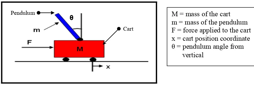
The inverted pendulum system is a Control Engineering problem that is used in universities around the world. It is a suitable process to test prototype controllers due to its high non-linearity and lack of stability. The system consists of an inverted pole hinged on a cart which is free to move in the x-axis direction. The term “inverted” means opposite position and “pendulum” means a weight hung from a fixed point.
1.2 Problem Statement
Due to its importance in the field of control engineering, it has been a task of choice to be assigned for students to analyze the inverted pendulum model and propose a linear compensator according to the PID control law in the MATLAB environment.
1.3 Scope
The scope of this final year project is to design a two dimensional inverted pendulum using MATLAB software. This project will focus on the design of the inverted pendulum controller using PID (proportional integral derivative) close loop system. The design also can able to control the inverted pendulum in the upright position when the working control model is achieved. PID controller needs to stabilize the angle of inverted pendulum in the simulation environment.
1.4 Objectives
The aim of this project is to design and build a working control model that can balance two dimensional inverted pendulum in an upright position by using MATLAB software. Throughout this project, the following objectives will be achieved:
a) To conduct literature study on existing controller designs for the inverted pendulum.
b) To design and build a control model for 2 dimensional inverted pendulum using PID controller.
1.5 Brief History of Inverted Pendulum
The simple linear pendulum has long proved a useful model for more complicated physical systems, and its behavior in the small-amplitude limit provides a realistic yet solvable example for students in introductory classes. While the force-free, frictionless pendulum can be solved exactly for all amplitudes in terms of elliptic integrals, the solution is hardly illuminating, rarely found useful, and when damping and external driving are included, the equations of motion become intractable. With the advent of desktop computers, however, it has become possible to study in some detail the rich nonlinear dynamics of the damped, force driven pendulum and gain significant insight into its sensitivity to initial conditions for certain values of the system parameters (Chye, 1999).
In 1581, Galileo, a physicist, began studying at the University of Pisa. While at the University of Pisa, Galileo began his study of the pendulum while, according to legend, he watched a suspended lamp swing back and forth in the cathedral of Pisa. However, it was not success until 1602 that Galileo made his most notable discovery about the pendulum. The period (the time in which a pendulum swings back and forth) does not depend on the arc of the swing (the isochronism). Eventually, this discovery would lead to Galileo's further study of time intervals and the development of his idea for a pendulum clock (Helden, 2004).
Early studies of the inverted pendulum system were motivated by the need to design controllers to balance rockets during vertical take-off. At the instance of time during launch, the rocket is extremely unstable. Similar to the rocket at launch, the inverted pendulum requires a continuous correction mechanism to stay upright, since the system is unstable in open loop configuration. This problem can be compared to the rocket during launch. Here, rocket boosters have to be fired in a controlled manner, to maintain the rocket upright (Chye, 1999).
The inverted pendulum is a classic problem in dynamics and control theory and widely used as benchmark for testing control algorithms (PID controllers, neural networks and genetic algorithms). Variations on this problem include multiple links, allowing the motion of the cart to be commanded while maintaining the pendulum, and balancing the cart-pendulum system on a see-saw. The inverted pendulum is related to rocket or missile guidance, where thrust is actuated at the bottom of a tall vehicle. Another way that an inverted pendulum may be stabilized, without any feedback or control mechanism, is by oscillating the support rapidly up and down. If the oscillation is sufficiently strong (in terms of its acceleration and amplitude) then the inverted pendulum can recover from perturbations in a strikingly counterintuitive manner (Jeffers, 2001).
Figure 1.1: Inverted Pendulum (Callinan, 2003)
Besides classroom theory and various control design methods, digital control exposure is important to the many practical aspects of implementing a digital control system. This requires a good foundation in control theory as well as knowledge in computer interfacing techniques, system modeling, instrumentation and digital signal processing. The modeling of inverted pendulum shall be created in MATLAB.
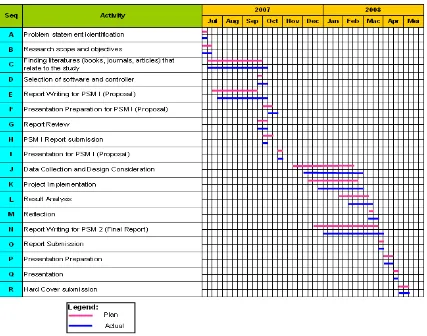
1.6 Project Schedule for Final Year Project
Table 1.1 shows the Gantt chart for the study which will be carried out through a two semester period.