iii
Dedication
This book is especially dedicated to my supervisor, all respective UTeM staffs and friends for their undivided help and guidance in enabling me to gain experience and
iv
“I declare that this report is done by my own exclude the citation with the mentioned references for each”
Signature:………...
v
ACKNOWLEDGEMENT
vi
ABSTRACT
vii
ABSTRAK
viii
TABLE OF CONTENT
CHAPTER TOPIC PAGE
DEDICATION iii
DECLARATION iv
ACKNOWLEDGEMENT v
ABSTRACT vi
ABSTRACT (B. MELAYU) vii
TABLE OF CONTENT viii
LIST OF FIGURES x
LIST OF TABLES xiii
LIST OF ABBREVIATIONS xiv
LIST OF APPENDICES xv
CHAPTER 1 INTRODUCTION
1.1 Background research 1 1.2 Problem Statement 3
1.3 Objectives 4
1.4 Scope 5
CHAPTER 2 LITERATURE REVIEW
2.1 Thermoelectric background history 6
2.2 Thermoelectric Theory. 8
2.3 How Thermoelectric coolers work. 8
2.4 The Seebeck Effect 10
ix
2.6 Typical thermoelectric system 13
configured.
CHAPTER 3 METHODOLOGY
3.1 Listing apparatus 15
3.2 Operating procedure 16
CHAPTER 4 EXPECTED RESULT
4.1 Results 21
4.2 Sample calculation. 29
4.3 Heat that effected the thermoelectric 32 cooler.
4.3 Data analysis from result. 33
CHAPTER 5 DISCUSSION
5.1 Discussion from the graph 37
CHAPTER 6 CONCLUSION AND RECOMMENDATION 40
REFERENCES 41
BIBLIOGRAPHY 43
APPENDICES 44
x
LIST OF FIGURES
NO. TITLE PAGE
1.1 Thermoelectric device CP2-127-06L 2
2.1 The first idea of thermoelectric device 7
(http://thermoelectric.com/2005/old/photo-3.htm)
2.1.1 The first thermoelectric cooler been made 7
(http://thermoelectric.com/2005/old/photo-3.htm)
2.3.1 Diagram of a typical thermoelectric cooler 9
(Source: International Journal of Refrigeration Volume 23, Issue 3, May 2000)
2.3.2 Illustrates an "N-type" semiconductor element 9 Utilize to facilitate the Peltier effect
xi
NO. TITLE PAGE
2.6.1 Conceptual drawing of air-to-air Thermoelectric 14 Cooling System (http://www.tellurex.com)
3.2.1 Drawing line 16
3.2.2 Hole at the upper of the box 17
3.2.3 Make a hole 17
3.2.4 Aluminum and fan been Screw 17
3.2.5 View inside box 18
3.2.6 View outside box 18
3.2.7 Thermoelectric with thermal grease 18
3.2.8 Thermoelectric between two heat sink 18
3.2.9 Solidwork drawing of assemble the 19
thermoelectric
3.2.10 Solidwork drawing fabrication the thermoelectric cooler. 19
4.2.1 performance curve graph for thermoelectric 28
4.3.1 Graph cooler box temperature versus time. 31
4.3.2 Graph water temperature versus time. 32
4.3.3 Graph QCversus time 33
4.3.4 Graph COP versus time 34
4.3.5 Journal variation of TCwith loaded water 500 ml 36 from the institute of refrigeration and cyrogenics,
xii
NO. TITLE PAGE
4.3.6 Journal of variation of cooling load and COP 37 from the institute of refrigeration and cyrogenics,
Y.J Dai. R Z Wang L, Ni.
xiii
LIST OF TABLES
NO. TITLE PAGE
1.1 Specification of thermoelectric device CP2-127-06L 3
4.1 Result for box A (Time taken every 1 minute) 23
4.1.1 Result for box A (Time taken continued every 23 5 minutes with constant voltage)
4.1.2 Result for box A Calculation table 24 4.2 Result for box B (Time taken every 1 minute) 24 4.2.1 Result for box B (Time taken continued every 25 5 minutes with constant voltage
4.2.2 Result for box B Calculation table 25 4.3 Table for box C(Time taken every 1 minute) 26 4.3.1 Table for box C (Time taken continued every 26 5 minutes with constant voltage)
xiv
LIST OF ABBREVIATION
COP = coefficient of performance
I = current through the thermoelectric module (amp)
Kt = total thermal conductivity of thermoelectric module, (W°C−1)
QC = cooling load (W)
P = electric power supplied to the thermoelectric module (W) R = total electrical resistance of thermoelectric module (ohm) TH = hot-end temperature of the thermoelectric module (K) TC = cold-end temperature of the thermoelectric module (K) V = voltage to the thermoelectric module (volt)
α = Seeback coefficient of thermoelectric module (V°C−1)
xv
LIST OF APPENDICES
APPENDIX TITLE PAGE
1 Manual DC voltage regulator in parallel. 41
2 DC Voltage regulator GPC 43
3 Parallel wire connected to voltage regulator 43
4 Thermal grease 44
5 1000ml bottle water 44
6 Boxes 44
7 Thermoelectric cooler complete with current at45 fan and supply to voltage regulator
for thermoelectric
8 Install the thermoelectric at bottom of box 45
9 Solidwork drawing before assembly. 46
10 Solidwork drawing after assembly. 46
11 Melcor performance specification and 47
the performance graph given by the manufacturer
12 Manual of the PicoLog TC-08 51
1
CHAPTER 1
INTRODUCTION
1.1.1 Background research
According to the Brooks Samuel Mann, (2006), a thermoelectric device is a solid
state heat pump that uses the Peltier effect, and works in conjunction with a heat sink to
remove heat from a system. Most applications that require cooling do not employ
thermoelectric because of the low values of efficiency that are inherent in thermoelectric
cooler. A thermoelectric requires relatively large amounts of electrical power in order to
produce a cooling effect. In fact, more conventional systems such as vapor compression
refrigeration cycles have as much as a 3 to 1 advantage in efficiency over
thermoelectric. However, thermoelectric can be useful in certain applications where the
advantages outweigh the disadvantages. Thermoelectric device are solid state, and so
they produce no noise and require little to no maintenance. They also are quite small
when compared to other systems, and so can be useful when there is a limited amount of
space in a system
Due to that, there are studies made specifically to focus on fabricate the
thermoelectric cooler and also investigate the performance of thermoelectric cooler. In
2
(COP) been calculated using the formulae and the value of heat pumped of
thermoelectric can be known from the graph that manufacturer given according the
value of temperature difference get from the experiment.
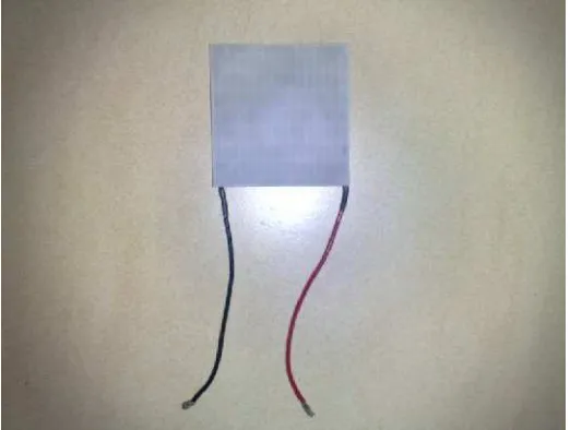
Figure 1.1 shows the thermoelectric that will be use on fabrication the
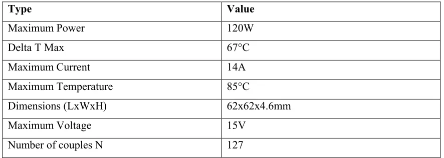
thermoelectric cooler made by Marlow company. The table 1.1 shows completely
specification of this thermoelectric given by manufacturer. Despite their small size,
these devices can all create temperature differences of around 67 °C . They can also be
stacked on top of each other to create even larger temperature differences. From the data
that company given when buying this thermoelectric, can know that the maximum
power of this thermoelectric can achieve is 120W.The maximum current and voltage is
14 Ampere and 15 Volts.Also known that the number of couples N is 127.
3
Table 1.1 Specification of thermoelectric device CP2-127-06L
Type Value
Maximum Power 120W
Delta T Max 67°C
Maximum Current 14A
Maximum Temperature 85°C
Dimensions (LxWxH) 62x62x4.6mm
Maximum Voltage 15V
Number of couples N 127
The current applications of thermoelectric besides cooler are minimal because of
the low efficiency values associated with them. Besides to make a cooler box, there are
some lists are possible uses of thermoelectric as a temperature stabilization of
bolometers and ferroelectric detectors, uses to cold the computer processor, using in
laser diode arrays in fiber optic systems, and maintaining constant viscosity in ink jet
printers.( Scott T. Huxtable 1996)
1.2 Problem statement
Thermoelectric module is a simple device that can be used as a cooling element.
This system has the merits of being light, reliable, noiseless and low cost compare to the
refrigerant as a heat carrier in the refrigeration system. From those reason of being light,
reliable and noiseless can get an idea to fabricate the thermoelectric cooler. The problem
that will be examined in this research is about the performance of temperature using
thermoelectric device can be cooled in three different boxes with different size. In this
research, the problem is whether the thermoelectric device can make sure the box that
been made about is enough to make the box been cooled around 10°C. To generate this
4
side temperature, and amount of heat absorbed at cold surface to maintain cold side
must be known. The surface of hot side temperature determined by two major
parameter, the temperature of the environment which heat rejected and efficiency of the
heat exchanger which are using the aluminum heat sink with the fan to rejected heat to
environment. The thermal greese is important think to make sure the heat been rejected
smoothly. The temperature difference are been used in graph from the manufacturer to
determine the heat pumped by the model with different value of current and voltage.
With this value of heat pump, the coefficient of performance (COP) of thermoelectric
cooler can be determined using the formulae. The graph can be plotted to show the
performance of thermoelectric.
1.3 Objective
There are 2 main objective of this project that have been set as a project goals in
order to accomplish this thesis are:
1. Fabricate thermoelectric cooler.
2. Investigate the performance of thermoelectric cooler box after fabrication based
5
1.4 Scope
In order to complete this project in the particularly time, it demand a lot of time
consuming and resources from every types of medium such as journals, text book and
other references that related to thermoelectric study field. In generally, the scope of
study that consisted in this thesis accomplishment is:
1. Literature review and study on thermoelectric device system
2. Student need to fabricate a simple thermoelectric cooler with three different
boxes
A: 47cmx45cmx32cm
B: 48cmx45cmx32cm
C: 60cmx45cmx32cm
3. Run some experimental procedures to determine the performance of
thermoelectric cooler.
4. Choose the suitable box for this thermoelectric device 120W that can reach
temperature to 100C.
6
CHAPTER 2
LITERATURE REVIEW
2.1 Thermoelectric background history.
According to Brooks Samuel Mann in the year 2006, the study of thermoelectric
began in 1822 when Thomas Johann Seebeck, a German physicist, noticed that two
dissimilar metals in a closed loop caused a compass needle to deflect when the two
metals were held at different temperatures. This meant that an electric field was created
between the two metals, thus inducing a magnetic field to deflect the needle. Seebeck
later discovered that some metals were able to create stronger fields with the same
temperature difference, and that the amount of deflection in the needle was proportional
to the temperature difference between the two conducting metals. These principles make
up the foundations of thermoelectric, and for his discoveries the Seebeck coefficient (the
voltage produced between two points of a conductor where a uniform temperature
difference of 1K exists between those two points) was named after the founding father
of thermoelectric.
In 1834 a French watchmaker named Jean Charles Athanase Peltier discovered
7
could create a temperature difference between the two dissimilar metals. Although
Peltier is generally credited with the discovery of thermoelectric cooling, he did not
fully understand the physics of the phenomenon. The full explanation was given four
years later by Emil Lenz, who showed that a drop of water on a bismuth-antimony
junction would freeze when electrical current was applied one way, and melt again
[image:22.612.230.465.234.414.2]when the current was reversed. (Brooks Samuel Mann 2006)
Figure 2.1:The first idea of thermoelectric device.
(http://thermoelectric.com/2005/old/photo-3.htm)
Figure 2.1.1: The first thermoelectric cooler been made
[image:22.612.220.437.505.664.2]8
2.2 Thermoelectric Theory
Thermoelectric phenomenon describes the relationship between the flow of heat
and electricity. These are the Seebeck effect, the Peltier effect, and the Thomson effect .
The thermoelectric properties of a material are measurable and are bulk properties of a
given material just like electrical or thermal conductivity. The Seebeck, Peltier, and
Thomson relations are commonly used to characterize materials that exhibit
thermoelectric properties. (Elaine P. Scott)
2.3 How Thermoelectric coolers work.
Thermoelectric coolers are solid state heat pumps that operate on the Peltier
effect, the theory that there is a heating or cooling effect when electric current passes
through two conductors. A voltage applied to the free ends of two dissimilar materials
creates a temperature difference. With this temperature difference, Peltier cooling will
cause heat to move from one end to the other. A typical thermoelectric cooler will
consist of an array of p- and n- type semiconductor elements that act as the two
dissimilar conductors. The array of elements is soldered between two ceramic plates,
electrically in series and thermally in parallel. As a dc current passes through one or
more pairs of elements from n- to p-, there is a decrease in temperature at the junction
("cold side") resulting in the absorption of heat from the environment. The heat is
carried through the cooler by electron transport and released on the opposite ("hot") side
as the electrons move from a high to low energy state. The heat pumping capacity of a
cooler is proportional to the current and the number of pairs of n- and p- type elements
9
Figure 2.3.1 - Diagram of a typical thermoelectric cooler
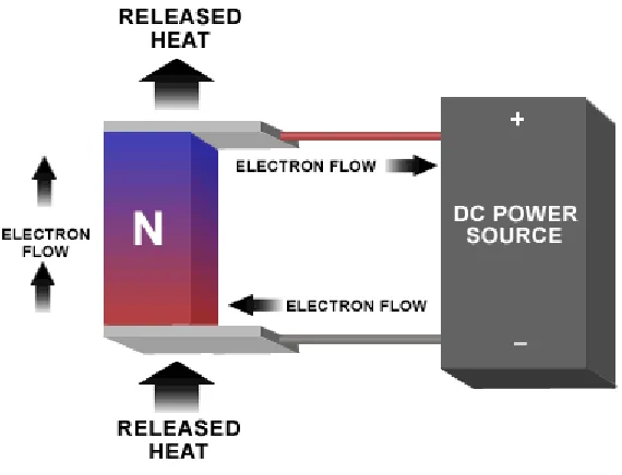
N and P type semiconductors (usually Bismuth Telluride) are the preferred materials
used to achieve the Peltier effect because they can be easily optimized for pumping heat
and due to the ability to control the type of charge carrier within the conductor.
Figure 2.3.2; Illustrates an "N-type" semiconductor element utilized to facilitate the
[image:24.612.182.467.441.659.2]