ISSN: 1693-6930
accredited by DGHE (DIKTI), Decree No: 51/Dikti/Kep/2010 351
Self Oscillating Mixer with Dielectric Resonator for Low
Noise Block Application
Achmad Munir*, Endon Bharata Radio Telecommunication and Microwave Laboratory
School of Electrical Engineering and Informatics, Institut Teknologi Bandung (ITB) Jalan Ganesha 10 Bandung, 40132, Indonesia, Ph./Fax: +6222-2501661/2534133
e-mail: munir@ieee.org*1, endonb@stei.itb.ac.id2
Abstrak
Dalam makalah ini, pengembangan pencampur berosilasi diri (self oscillating mixer, SOM) sebagai bagian dari blok derau rendah (low noise block, LNB) untuk penerima televisi satelit diteliti secara numerik dan eksperimental. Berbeda dengan pencampur lain, SOM yang dikembangkan tidak memerlukan perangkat osilator lokal secara terpisah karena SOM ini menghasilkan sinyal osilator lokal sendiri. SOM ini disusun menggunakan rangkaian terintegrasi gelombang mikro monolitik (monolithic microwave integrated circuit, MMIC) yang didalamnya terdiri dari dua buah transistor bipolar yang disusun sebagai sebuah pasangan Darlington dan sebuah peresonansi dielektrik untuk membangkitkan sinyal osilator lokal. SOM ini dirancang untuk berosilasi pada frekuensi 3,62GHz yang dikendalikan dari 50Ω pembangkit sinyal. Purwarupa SOM ini difabrikasi pada sebuah subsrat dielektrik papan laminasi hidrokarbon/keramik (RO4350B) yang diperkuat dengan kaca yang memiliki ketebalan 0,762mm dan permitivitas relatif 3,66. Prototipe ini kemudian dikarakterisasi secara eksperimental dan menghasilkan penguatan konversi sebesar 8dB dengan perbandingan gelombang tegangan berdiri (voltage standing wave ratio, VSWR) pada terminal masukan dan keluaran kurang dari 2 pada pita frekuensi operasi dari 2520MHz sampai 2670MHz.
Kata kunci: blok derau rendah, MMIC, pencampur berosilasi diri, peresonansi dielektrik
Abstract
In this paper, the development of a self oscillating mixer (SOM) as part of a low noise block (LNB) for a satellite television receiver is investigated numerically and experimentally. In contrast to other mixers, the developed SOM requires no separate local oscillator as it generates own local oscillator signal. The SOM is developed using a monolithic microwave integrated circuit (MMIC) comprised of two bipolar transistors coupled as a Darlington pair and a dielectric resonator to establish a local oscillator signal. The SOM is designed to oscillate at 3.62GHz driven from 50Ω signal generator. The prototype of SOM is fabricated on a dielectric substrate of glass-reinforced hydrocarbon/ceramic lamination (RO4350B) board which has a thickness of 0.762mm and relative permittivity of 3.66. The prototype is then characterized experimentally and exhibits a conversion gain of 8dB with the input and output voltage standing wave ratio (VSWR) less than 2 across the 2520MHz to 2670MHz operating frequency band.
Keywords: dielectric resonator, low noise block, MMIC, self oscillating mixer
1. Introduction
A satellite television receiver is equipment which is designed to receive broadcasted television signals which transmit directly from a satellite. Television broadcasting through satellite has been conducted by Televisi Republik Indonesia (TVRI) to cover the areas or islands those are not served by conventional broadcasting system. Unfortunately, not all people are able to have satellite television receiver due to its high price. This is because of the used satellite is a communication satellite which has a low transmitting power; therefore the receiver requires a large size of and expensive antenna. This situation has been exploited by the private sector to initiate to build a network of satellite television broadcasting using S-band frequency with high power. As a result, the price of satellite television receiver goes down relatively inexpensive allowing residents can have their own satellite television receiver.
2520-2670MHz and 22 transponders for Ku-band at frequency band of 11.45-11.7GHz. The satellite is the replacement for Cakrawala-1 or Indostar-1 satellite which has been operated since 1997 at orbit slot of 107.7o east longitude. Actually, the market for satellite television receiver in Indonesia is very large due to only a small number of Indonesia’s population has the receiver. However, this opportunity is currently exploited by foreign companies by flooding Indonesia with their products as no national industry involves in developing or assembling its own satellite television receiving system. Therefore, in this paper, a self oscillating mixer (SOM) with dielectric resonator as part of low noise block (LNB) is proposed to be developed as an alternative or supplement product and to help national industry to fill the market in Indonesia with their own design of satellite television receiver. The developed SOM that requires no separate local oscillator is using a monolithic microwave integrated circuit (MMIC) and a dielectric resonator.
Basically, an SOM has a function to simplify some receiver layout by combining mixer and local oscillator in a same board [1]-[4]. A balanced layout allows generating the mixing signal with low cost components. Hence, the use of dielectric resonator as a balancing element contributes in phase stability which is required in satellite television receiver. By using these items a self-contained receiver for satellite television purposes can be realized. Some investigation of SOM has been studied extensively, such as dielectric resonator stabilized self oscillating mixers for fundamental frequency [1], balanced quasioptical self oscillating mixers of fundamental frequency [5], and self oscillating single device mixer of second harmonic [6]. In contrast to other mixers, the SOM developed here is designed to oscillate at 3.62GHz driven from 50Ω signal generator and is comprised of an MMIC comprised of two bipolar transistors coupled as a Darlington pair and a dielectric resonator to establish a local oscillator signal. The prototype of SOM is then fabricated on a dielectric substrate of glass-reinforced hydrocarbon/ceramic lamination (RO4350B) board with the thickness of 0.762mm and relative permittivity of 3.66 [7].
2. Self Oscillating Mixer Design
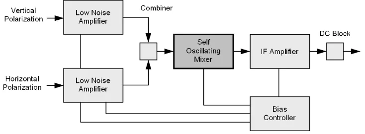
In general, as shown in Figure 1, the function of self oscillating mixer (SOM) as part of LNB is to change the frequency of received signals into the lower frequency with the help of a MMIC component and a dielectric resonator, before feeding the signals into some decoder for an advanced processing to obtain images and sounds. Here, the proposed SOM requires no separate local oscillator as it generates own local oscillator signal. This type of converter is low cost and compact for using in the low noise block of satellite television receiver.
Figure 1. Block diagram of a low noise block
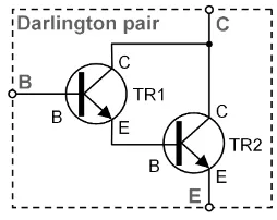
transistors that are connected together are applied as the output to feed to next circuits. In addition, the output is also used to give a feedback loop that is operable for coupling signals at the frequency of local oscillator from the output side to the input side of transistors. The Darlington-connected transistors perform three functions, namely mixing, amplifying and oscillating. The configuration mixes the input and local oscillator signals, and then amplifies the obtained output signal. Hence, in combination with the feedback loop, the configuration oscillates at the frequency of local oscillator. The first transistor (TR1) will limit the amplitude of oscillations and generate the product of frequencies, whilst the second transistor (TR2) acts as an amplifier. The feedback loop of configuration including a dielectric resonator will determine the frequency of local oscillator.
Figure 2. Configuration of Darlington pair
The down conversion of received signal of 2.52GHz-2.67GHz to the IF frequency signal of 950MHz-1100MHz is accomplished using a radio frequency integrated circuit (RFIC) frequency converter MSA-0836 from Agilent. The RF signal is provided to the input of MMIC by preceding low noise amplifier stages. The local oscillator signal is created by establishing a feedback loop around the MSA-0836 using a 3.62GHz dielectric resonator. This loop has to provide 360 degree phase shift around the MMIC at the local oscillator frequency of 3.62GHz and has a loss less than the MMIC gain at that frequency, as given by the following equations.
n C R
A +Φ +Φ =2π
Φ , where n =0, 1, 2, ... (1)
dB 0
> −
− R C
A L L
G (2)
where ΦA, ΦR and ΦC are the insertion phase of MMIC, the dielectric resonator and the
remaining part of feedback circuit at f0, respectively. GA, LR and LC are the MMIC gain, the
resonator loss and the loss of other feedback components, all of them in decibel unit.
The proposed SOM is designated to oscillate at resonant frequency of 3.62GHz which is driven from 50Ω generator signal and loaded with 50Ω termination. As a consequent, the input and output terminations that couple with 50Ω load into the SOM circuit at 3.62GHz have to be included between the SOM and the input filter as well as between the SOM and the output filter. The schematic diagram of SOM circuit is shown in Figure 3 [11]. The dielectric resonator is then coupled between the input and output of MSA-0836 with the coupling coefficient will control the overall conversion gain and output of 1dB compression point.
In the schematic diagram shown in Figure 3, the dielectric resonator is placed at an arbitrary distance from each microstrip transmission line with the coupling that is optimized by varying spacing between the dielectric resonator and the dielectric substrate for optimum performance. This is accomplished by substituting low loss spacers of different thickness. The length of
l
1 should be 90 degrees at the oscillation frequency. This construction will reflect low impedance; hence a current will reach a maximum value at the point where the dielectric resonator is coupled to the transmission line. The length of (l
1+l
2) should be equal to 180 degrees at the RF frequency, which will reflect high impedance at the RF input to prevent loading. Whilst, the length of (2l
2+2l
3) together with the phase shift through the device should be 360 degrees at the oscillation frequency. To obtain each length, e.g.l
1,l
2 andl
3, the analysis is carried out numerically. By using a glass-reinforced hydrocarbon/ceramic laminate (RO4350B) board with the thickness and the relative permittivity of 0.762mm and 3.66, respectively and an MSA-0836 MMIC placed on it, the numerical analysis result shows that the length ofl
1,l
2andl
3 should be 12.15mm, 21.21mm and 1.49 mm respectively.3. Experimental Result
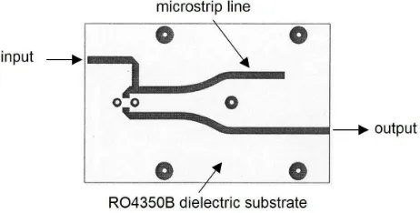
Based on the design explained in the previous section, the prototype of proposed SOM with dielectric resonator mounted on the board is then fabricated to be characterized experimentallye as shown in Figure 4. Whilst Figure 5 shows a picture of printed circuit board of SOM made of an RO4350B dielectric substrate with the thickness and relative permittivity are 0.762mm and 3.66, respectively. The experimental characterization results are depicted in Figures 6 and 7 for the frequency response of dielectric resonator and of MSA-0836 MMIC, respectively.
Figure 4. Picture of prototype of SOM in cavity with dielectric resonator
across the 2520MHz to 2670MHz operating frequency band are 1.5 and 1.8, respectively. Therefore, it should be noted that the prototype can accomplish the specifications needed by satellite television receiver.
Figure 5. Printed circuit board of SOM made of RO4350B dielectric substrate
Figure 6. Measured result of dielectric Figure 7. Measured result of MSA-0836
resonator frequency response MMIC frequency response
4. Conclusion
A self oscillating mixer (SOM) based on MSA-0836 MMIC from Agilent with dielectric resonator functioned to establish a local oscillator signal has been investigated numerically and experimentally. The prototype has also been fabricated using a glass-reinforced hydrocarbon/ceramic laminate (RO4350B) dielectric substrate with the thickness and relative permittivity are 0.762mm and 3.66, respectively. From experimental characterization, it has been demonstrated that the prototype exhibits a conversion gain of 8dB with the input and output VSWR less than 2 across the 2520MHz to 2670MHz operating frequency band. It can be concluded that the fabricated prototype can satisfy the requirements specified for satellite television receiver especially for Indostar-2 satellite that has transponders which works at S-band frequency of 2520MHz-2670MHz. In addition, further investigation on the development of overall LNB for satellite television receiver is still in progress where more reliable results will be reported later.
Acknowledgements
References
[1] Tajima T. GaAs FET Applications for Injection-Locked Oscillators and Self- Oscillating Mixers. IEEE Transaction on Microwave Theory and Technique. 1979; 27(7): 629-632.
[2] Gund CF, Lazarus MJ. An Indium-Phosphide Self-Oscillating Mixer for a 90-GHz Millimeter-Wave Receiver Application. Microwave and Optical Technology Letters. 1995; 8(3): 156-160.
[3] Dussopt L, Laheurte JM. Cavity-Backed Antenna Integrating a Self Oscillating Mixer. Microwave and Optical Technology Letters. 1999; 21(2): 156-158.
[4] Fernandez M, Ver Hoeye S, Herran LF, Las Heras F. Design of High-Gain Wide-Band Harmonic Self-Oscillating Mixers. International Journal of Circuit Theory and Application. 2010; 38: 551–558.
[5] Hwang VD, Itoh T, Quasi-Optical HEMT and MESFET Self-Oscillating Mixers. IEEE Transaction on Microwave Theory and Technique. 1988; 36(12): 1701-1705.
[6] Roberts MJ, Iezekiel S, Snowden CM. A Compact Subharmonically Pumped MMIC Self Oscillating Mixer for 77 GHz Applications. Proceeding of IEEE Microwave Theory and Technique-Society (MTT-S). Baltimore.1998; 1435-1438.
[7] Rogers Cooperation Data Sheet. RO4000® Series High Frequency Circuit Materials. 2010.
[8] Mitchell MP, Branner GR. A Novel Low-Noise Down Converter System using a Microstrip Coupled Transmission-Mode Dielectric Resonator. IEEE Transaction on Microwave Theory and Technique. 1987; 35: 591-594.
[9] Kipnis I, Khanna APS. 10 GHz Frequency Converter IC using a Silicon Bipolar Darlington-Connected Transistor Pair. Procedding of IEEE Bipolar Circuits and Technology Meeting. 1986; 61-62.
[10] Kipnis I, Khanna APS. Large-Signal Computer-Aided Analysis and Design of Silicon Bipolar MMIC Oscillators and Self-Oscillating Mixers. IEEE Transaction on Microwave Theory and Technique. 1989; 37: 558-564.