COORDINATION PROTECTION SYSTEM IN INDUSTRIAL PLANTS
AHMAD TARMIZI BIN MD NOR
This report is submitted in partial fulfillment of this requirement for the award of Bachelor of Electronic Engineering (Industrial Electronic) With Honors
Faculty of Electronic and Computer Engineering Universiti Teknikal Malaysia Melaka (UTeM)
UNIVERSTI TEKNIKAL MALAYSIA MELAKA
FAKULTI KEJURUTERAAN ELEKTRONIK DAN KEJURUTERAAN KOMPUTER
BORANG PENGESAHAN STATUS LAPORAN PROJEK SARJANA MUDA II
Tajuk Projek : COORDINATION PROTECTION SYSTEM IN INDUSTRIAL PLANTS
Sesi
Pengajian : 200/2010
Saya AHMAD TARMIZI BIN MD NOR
(HURUF BESAR)
mengaku membenarkan Laporan Projek Sarjana Muda ini disimpan di Perpustakaan dengan syarat-syarat kegunaan seperti berikut:
1. Laporan adalah hakmilik Universiti Teknikal Malaysia Melaka.
2. Perpustakaan dibenarkan membuat salinan untuk tujuan pengajian sahaja.
3. Perpustakaan dibenarkan membuat salinan laporan ini sebagai bahan pertukaran antara institusi pengajian tinggi.
4. Sila tandakan ( √ ) :
SULIT* (Mengandungi maklumat yang berdarjah keselamatan atau kepentingan Malaysia seperti yang termaktub di dalam AKTA RAHSIA RASMI 1972)
TERHAD* (Mengandungi maklumat terhad yang telah ditentukan oleh organisasi/badan di mana penyelidikan dijalankan)
TIDAK TERHAD
Disahkan oleh:
__________________________ ___________________________________ (TANDATANGAN PENULIS) (COP DAN TANDATANGAN PENYELIA)
Alamat Tetap: NO 21 JALAN NAKHODA KANAN,
iii
“I hereby declare that this is report is the result of my own work except for quotes as citied in the references.”
Signature :………
iv
“I hereby declare that I have read this report and in my opinion this report is sufficient in terms of scope and quality for the award of Bachelor of Electronic Engineering
(Industrial Electronics) With Honors.”
Signature : ………..
Supervisor’s Name : FARAH SHAHNAZ BINTI FEROZ
v
vi
ACKNOWLEDGEMENT
vii
ABSTRACT
viii
ABSTRAK
ix
TABLE OF CONTENTS
CHAPTER CONTENT PAGE
PROJECT TITLE
BORANG PENGESAHAN STATUS LAPORAN
DECLARATION iii
SUPERVISOR DECLARATION iv
x
2 LITERATURE REVIEW
2.1 Literature review overview 9
2.2 Journal paper for research 9
2.2.1 Journal 1 10
2.2.2 Journal 2 11
2.2.3 Journal 3 12
2.2.4 Journal 4 13
2.3 Fuse 14
2.3.1 Fuse specification is normally
based on the following four factors 16
2.3.2 Fuse Standards 17
2.3.3 Power Fuse 18
2.4 Relay 19
2.4.1 General Discussion of Protective
Relay System 19
2.4.2 Identifying Relay Function 20
2.4.3 Thermal Overload Relay 22
2.4.3.1 Thermal Overload Relay 22 2.4.3.2 Characteristic for Thermal Relay 23 2.4.4 Over current-Relay Types and Their
Characteristic Curves 25
2.5 Circuit Breaker 26
2.5.1 Current Levels to Be Broken 28 2.5.2 Circuit Breaker Functions 29
2.5.3 Ratings 30
2.6 Motor 32
2.6.1 Protection Schemes 34
2.6.2 Circuit protection 35
xi
3 METHODOLOGY
3.1 Literature Overview 37
3.2 Visit to available industrial and consultant firm, meet with
3.4.4 Convert single diagram into reactance
Diagram 38
3.4.5 Determine short circuit current at different
fault point 39
3.4.6 Determine symmetrical value of
short circuit 39
3.4.7 Determine asymmetrical value of
short circuit 39
3.5 Result and discussion 39
3.6 Conclusion 39
4 RESULT AND DISCUSSION
4.1 Numerical Example of Short Circuit
Calculation in Industrial Power System 41
4.2 Steps and Calculation 41
4.2.1 Draw single line diagram of
an industrial power system 42
xii 4.2.3 Convert the various reactance values 44 4.2.4 Convert the single line diagram 47
4.2.5 Combine all reactance 47
4.2.6 Determine the symmetrical 68 4.3 Selection and Coordination of Breakers,
Fuses and Relays 75
5 CONCLUSION
5.1 Summary 85
5.2 Recommendation for future project 87
5.3 Commercialization potential 87
REFERENCE 88
xiii
LIST OF TABLE
NO TITLE PAGE
2.1 Abbreviated List of Commonly Used Relay Device Function Number 21 2.2 Commonly Used Suffix Letters Applied to Relay Function Numbers 22 2.3 Typical Tap Ranges and Settings of Time over current Relays 25 2.4 Typical Interrupting Current Ratings of Molded Case Circuit Breaker
for Commercial and Industrial Applications 31
2.5 Typical Interrupting Current Ratings of Molded Case Circuit
Breaker – Current Limiting and Fused Circuit Breaker 32
2.6 Maximum Rating and Setting 35
xiv
LIST OF FIGURE
NO TITLE PAGE
1.1 Protective device functional elements 3
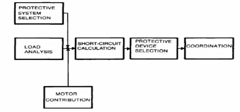
1.2 Sequence of steps in System Protection and Coordination 4
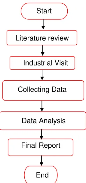
1.3 Project flowchart 7
2.1 Cutaway view 15
2.2 The link melts and an arc is establish under sustained overload current 15 2.3 The “open” link after clearing the overload current 15
2.4 200A Industrial fuse. 80 kA breaking capacity 16
2.5 UL Classifications 17
2.6 Solid-Material Boric-Acid Power Fuse Rated 14.4kV with
Controlled-Venting Device: 200A Indoor-Disconnecting Type 19
2.7 Typical of Thermal Overload Relay 23
2.8 Typical Thermal Relay Time / Current characteristic 24 2.9 Comparison of Typical Curves Shapes for over current Relays 26
2.10 A 2 pole Circuit Breaker 27
2.11 Front panel of a 1250A air circuit breaker manufactured by ABB. 29
2.12 Squirrel cage motor 33
2.13 Drawing of rotor 33
3.1 Flow Chart for Research 40
4.0 Single line diagram of selected industrial power system 43
4.1 Reactance diagram 47
xv
4.3 Combining Two Parallel Branches 48
4.4 Combining Several Parallel Branches 48
xvi
4.34 Step 5. Series branches 67
4.35. Typical 60Hz Peak Let Through Current. 75
4.36 Class L Current Limiting Fuse 76
CHAPTER 1
INTRODUCTION
Industrial power systems should be designed to provide the electric energy needed to power equipments in a safe, reliable and economical way. If only normal operation is practiced (without system protection and coordination), system operation would be inadequate because of possible equipment failure or human error. System protection and coordination serves to minimize damage to a system and its components in order to limit the amount and duration of any service interruption occurring to any portion of the system. This practice is implemented at the system design stage. Information on protection and coordination principles are designed to protect industrial power systems against any abnormalities that could be expected to occur in the course of system operation.
2 protection and coordination. This case study also deals with the proper selection, application, and coordination of the components which represent system protection for industrial plants.
1.1 Project background
The design of an electrical power system should minimize the effect of short circuit current that occur on the system itself or on the utilization of equipments that it supplies. One can design into the electric system features that will quickly isolate the affected portion of the system and maintain normal service for as much of the systems as possible and minimize damage to the affected portion of the system. In laying out electric power systems, the designer should keep the final design as simple as would be compatible with safety, reliability, maintainability and economic considerations.
A short circuit is an accidental low-resistance connection between two nodes of an electrical circuit that are meant to be at different voltages. This results in an excessive electric current on the network and potentially causes circuit damage, overheating, fire or explosion. Circuits may become overloaded simply by connecting larger or additional utilization equipment to the circuit. Overloads may be caused by improper installation and maintenance. Improper operating procedures are also a cause of equipment overload or damage.
3 Circuit breakers are interrupting devices only and must be used in conjunction with sensing devices to fulfill the detection function. It is an automatically-operated electrical switch designed to protect an electrical circuit from damage caused by overload or short circuit. Unlike a fuse, which operates once and then has to be replaced, a circuit breaker can be reset (either manually or automatically) to resume normal operation. Circuit breakers are made in varying sizes, from small devices that protect an individual household appliance up to large switchgear designed to protect high voltage circuits feeding an entire city.
Relays are compact analog, digital, and numerical devices that are connected throughout the power system to detect intolerable or unwanted conditions within an assigned area. They are, in effect, a form of active insurance designed to maintain a high degree of service continuity and limit equipment damage. Relay response to an input and causes circuit connection to close or open.
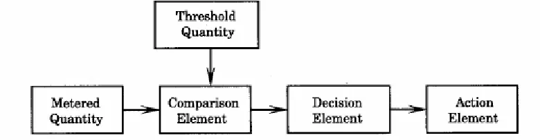
The protective device usually consists of several elements, shown in Figure 2.0 that are arranged to test the system condition, make decisions regarding the normality of observed variables, and take action as required.
Figure 1.0: Protective device functional elements
4 comparison indicates an alert condition, a decision element is triggered. If all checks are satisfied, an action element is released to operate, which usually means that circuit breakers are instructed to open and isolate a section of the network.
A protective system should be designed to recognize certain system abnormalities which, if undetected, could lead to damage of equipment or extended loss of service. The design and specification of the system components is an important part of the protective strategy. The protective system should also be designed for minimum loss-of-load, as shown in Figure 2.1. There is no need, usually, to de-energize the entire system because of an isolated fault. The system should have selectivity to isolate the fault such that the minimum interruption occurs.
The operation of protective equipment must be accurate and fast. Bulk power system reliability requires that systems survive severe fault conditions without causing a system collapse. This in turn requires fast, reliable protective system operation.
5
1.2 Project Objectives
The objectives of this project are stated below;
1. To determine and compare the characteristics, ratings, and settings of over current protective devices.
2. To determine the best method to limit the extent and duration of service interruption.
3. To determine the best system that can minimize damage to the system components involved in the failure
1.3 Problem statement
6
1.4 Scope
In this project, three assumptions are made:
Basic application of electrical devices like fuse, breaker, relay and motor.
Compare data between 3 factories.
Understanding short circuit formula and application.
Analyze main instrument and device.
There are two limitation levels that cannot be avoided in this project. First is to find information from trusted resources. Each system and machine has their own current supply. To get the real data, manual electric circuit diagram from the industry is taken. Certain information are confidential and not all company/factory are willing to expose their data. Next, data collection is handled by the company staff. I have no control as to when the data is collected and how data collection is handled. Human error that occur when taking the data also affects the analysis.
To analyze data, short circuit formula in industrial power system is used. All formula for each device is applied to this industry data.
1.5 Methodology project
7 consideration, selective coordination of protective devices and selection and application of protective device is done.
Figure 1.2: Project flowchart
The primary purpose of good selection and selective tripping of protective devices is to minimize system damage and limit the extent and duration of service interruption when failures occur. The minimum safety and reliability requirements should be met to assure satisfactory electrical system performance. Selective coordination technique’s main goal is to isolate the affected portion of the system quickly while maintaining normal service for the rest of the system. At the same time, the operation of other parts of the system that are not directly involved must be held until other protective devices are functioning as normal. This is called selectivity.
8 Minimum as well as maximum short-circuit values are required to predict selective operation of protective devices during fault currents. A short circuit study, therefore, is absolutely necessary for selective coordination settings. A coordination study is necessary to determine the characteristics and settings of all protective devices. The study should indicate the best combination of protection, thus assuring that the least load is interrupted in the least time while clearing any fault in the system. To localize the disturbance, the device should be selective in their operation; the one nearest to the faulty power source should operate first. If this device does not operate, the next device in line should take over.
1.6 Outline of PSM report