i
AUTOMATIC DETECTION USING HUMAN MACHINE INTERFACE (HMI)
ROHAIDAH BINTI MAHIDIN
This Report Is Submitted In Partial Fulfillment Of Requirement For The Bachelor Degree of Electronic Engineering (Industrial Electronic)
Fakulti Kejuruteraan Elektronik dan Kejuruteraan Komputer Universiti Teknikal Malaysia Melaka
ii
UNIVERSTI TEKNIKAL MALAYSIA MELAKA
FAKULTI KEJURUTERAAN ELEKTRONIK DAN KEJURUTERAAN KOMPUTER
BORANG PENGESAHAN STATUS LAPORAN
PROJEK SARJANA MUDA II
Tajuk Projek : AUTOMATIC DTETECTION USING HUMAN
MACHINE INTERFACE
Sesi Pengajian : 1 0 / 1 1
Saya ………..
(HURUF BESAR)
mengaku membenarkan Laporan Projek Sarjana Muda ini disimpan di Perpustakaan dengan syarat-syarat kegunaan seperti berikut:
1. Laporan adalah hakmilik Universiti Teknikal Malaysia Melaka.
2. Perpustakaan dibenarkan membuat salinan untuk tujuan pengajian sahaja.
3. Perpustakaan dibenarkan membuat salinan laporan ini sebagai bahan pertukaran antara institusi pengajian tinggi.
4. Sila tandakan ( √ ) :
SULIT*
*(Mengandungi maklumat yang berdarjah keselamatan atau kepentingan Malaysia seperti yang termaktub di dalam AKTA RAHSIA RASMI 1972)
TERHAD** **(Mengandungi maklumat terhad yang telah ditentukan oleh organisasi/badan di mana penyelidikan dijalankan)
TIDAK TERHAD
Disahkan oleh:
__________________________ ___________________________________
(TANDATANGAN PENULIS) (COP DAN TANDATANGAN PENYELIA)
iii
DECLARATION
“I hereby declare that this report is the result of my own work except for quaotes as cited in the references.”
Signature :………
Author : ROHAIDAH BINTI MAHIDIN
iv
“I hereby declare that I have read this report and in my opinion this report is sufficient in terms of the scope and quality for the award of Bachelor of Electronic
Engineering (Industrial Electronics) with Honours.”
Signature : ……….
Supervisor’s Name : Engr. MUZAFAR BIN ISMAIL
v
Dedicated to my lovely husband, Shaharuddin Bin Nordin, my parents, Mahidin
vi
ACKNOWLEDGEMENT
vii
ABSTRACT
viii
ABSTRAK
ix TABLE OF CONTENTS
PROJECT TITLE ... i
BORANG PENGESAHAN STATUS………...……ii
DECLARATION ... iii
ACKNOWLEDGEMENT ... iv
ABSTRACT ... v
ABSTRAK ... viii
LIST OF FIGURE Figure 1.1: Research Methodology ………..4
Figure 1.2: Gantt chart Project 1……….…..5
Figure 1.3: Gantt chart Project 2………...6
Figure 2.1: The PLC System……….8
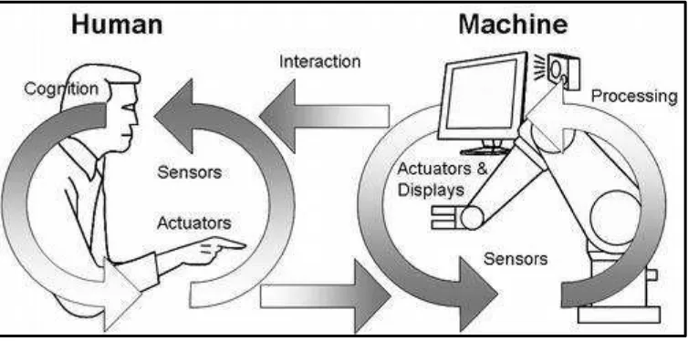
Figure 2.2: The interaction between human and machine………..10
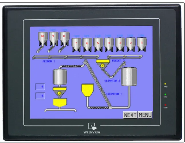
Figure 2.3: The Graphic User Interface………..11
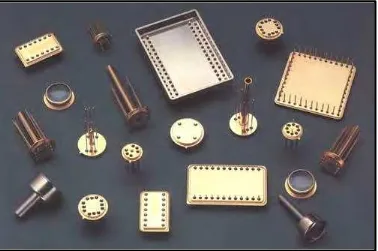
Figure 2.4: Varieties of sensors………..…13
Figure 3.1: Research Methodology……….14
Figure 3.2: A Simple Ladder Logic Diagram……….16
Figure 3.3: An Example of a Mnemonic Program and Equivalent Ladder Logic…..17
Figure 3.4: An Example of a Sequential Function Chart………18
Figure 3.5: An Example of a Structured Text Program………..19
Figure 3.6: PLC sequentially executes the stored program and gets new output result………...19
Figure 3.7: Typical Configurations for PLC……….. 21
Figure 3.8: Human Machine Interface of Mytek………22
Figure 3.9: Multi HMI Connection……….23
Figure 3.10: Panel Master Software………24
x
Figure 3.12: Control - Circuit………29
Figure 3.13: Flow Chart Before System Chosen Automatic mode or Manual mode………..31
Figure 3.14: Flow chart for the process in Automatic Detection Using Human Machine Interface………..32
Figure 3.15: Block Diagram for Automatic Detection using HMI……….33
Figure 4.1: GUI of Virtual HMI Main Screen………37
Figure 4.2: GUI of Virtual HMI Automatic Mode……….38
Figure 4.3: GUI of Virtual HMI Manual Mode……….39
Figure 4.4: GUI of Virtual HMI Input and Output Screen………40
Figure 4.5: Voltage and Dirt Level profile for bottle using LV-300 laser sensor….45 Figure 4.5: Completed project from front view………45
Figure 4.6: Completed project from top view ………..46
Figure 4.7: Completed project from side view………46
LIST OF TABLES Table 3.1: List of wall station components………27
Table 3.2: List of components in control box………28
Table 3.3: PLC Input, symbol and function………..34
Table 3.4: PLC Output, symbol and function………35
Table 4.1: Level of dirt in the bottle………..44
TABLE OF CONTENT………ix
CHAPTER 1 ... 1
INTRODUCTION ... 1
1.0 Background of Study ... 1
1.1 Objectives ... 2
1.2 Problem statement ... 2
1.3 Scope of work ... 3
1.4 Methodology ... 3
1.5 Organization of the Thesis ... 7
CHAPTER 2 ... 8
LITERATURE REVIEW ... 8
xi
2.1 Human Machine Interface (HMI) ... 9
2.2 Graphic User Interface ... 11
2.3 Sensors ... 12
CHAPTER 3 ... 14
RESEARCH METHODOLOGY AND PROCESS ... 14
3.0 Introduction ... 14
3.1 Installation of Main Project ... 15
3.2. Human Machine Interface ... 21
3.3 Logical Sensors ... 26
3.4 Installation of control panels and boxes ... 27
3.5 Installation of wiring systems ... 29
3.6 Installation of wiring and cabling ... 29
3.7 Testing and Commissioning ... 30
3.8 Function Description ... 30
CHAPTER 4 ... 36
RESULT AND DISCUSSIONS ... 36
4.0 Introduction ... 36
4.1 GUI of Virtual HMI ... 36
4.2 Discussion ... 41
4.3 Potential Problem ... 43
CHAPTER 5 ... 47
CONCLUSION ... 47
5.1. Conclusion ... 47
5.2 Future development... 48
REFERENCES ... 49
APPENDICES I ... 52
Ladder Diagram Manual Mode Using PLC Keyence KV – 1000 ... 52
Ladder Diagram of Automatic Mode Using PLC Keyence KV-1000 ... 53
Ladder Diagram of Output Using PLC Keyence KV-1000 ... 58
Ladder Diagram of Tank Level Using PLC Keyence KV – 1000 ... 61
Ladder Diagram of Frequency Converter Using PLC Keyence KV – 1000 ... 62
APPENDICES II ... 63
PLC Keyence KV – 1000 Function ... 63
1
CHAPTER 1
INTRODUCTION
1.0 Background of Study
2
1.1 Objectives
The followings are the objective of the project;
a) To develop a mini simulation model of Automatic Detection Using Human Machine Interface in the industrial control.
b) To design a graphic user interface that will facilitate in monitoring the process of the system.
c) To demonstrate how the HMI applications can be used in the industry.
d) To apply the knowledge in the manufacturing, instrumentation and control application.
1.2 Problem statement
3
1.3 Scope of work
This project involves the study on knowledge acquisition of interfacing among HMI, PLC and Hardware. This project will design the GUI for HMI system. The project
achievement is to design a graphic user interface that will facilitate in monitoring the
process of the system and to demonstrate how the HMI applications can be used in the industry. PLC programming and Graphic User Interface development will not covered in this paper.
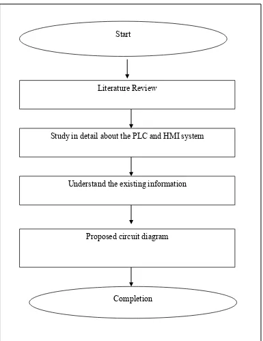
1.4 Methodology
followings:-4
Literature Review
Study in detail about the PLC and HMI system
Understand the existing information
Proposed circuit diagram Start
Completion
5
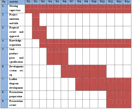
No. Activity W1 W2 W3 W4 W5 W6 W7 W8 W9 W10 W11 W12 W13 W14
1 Meeting
supervisor
2 Project
initiation and title
3 Proposal
review and approval
4 Knowledge
acquisition
5 Seek
product
price and
specification
6 Development
system set-up
7 Ladder
diagram development
8 Presentation
preparation
9 Presentation
review
6
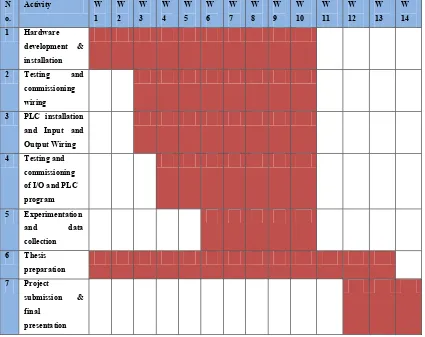
N o.
Activity W
1 W 2 W 3 W 4 W 5 W 6 W 7 W 8 W 9 W 10 W 11 W 12 W 13 W 14
1 Hardware
development & installation
2 Testing and
commissioning wiring
3 PLC installation and Input and Output Wiring 4 Testing and
commissioning of I/O and PLC program 5 Experimentation
and data
collection
6 Thesis
preparation
7 Project
submission & final
presentation
7
1.5 Organization of the Thesis
This thesis consists of five chapters including this introduction follow the university thesis standard which including objectives, scope of the works, problem statement and methodology. In second chapter present the literature review of introduction and uses of the equipment used in this project; PLC, HMI, GUI and sensors.
Presents the study which includes most of the related research methodology and process of the experiment detailed will be present at chapter three. Meanwhile the chapter four focused on presenting the results and discussions of the project. The discussion focused on the analyses with referring to the results obtained.
8
CHAPTER 2
LITERATURE REVIEW
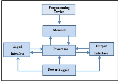
2.0 Programmable Logic Controller System
PLC programs are typically written in a special application on a personal computer, and then downloaded by a direct-connection cable or over a network to the PLC. The program is stored in the PLC either in battery-backed-up RAM or some other non-volatile flash memory. Often, a single PLC can be programmed to replace thousands of relays. Figure 2.1 illustrates the block diagram for a general PLC system.
Programming Device
Memory
Processor
Power Supply
Output Interface Input
Interface
9 PLCs can be programmed using standards-based programming languages. A graphical programming notation called Sequential Function Charts is available on certain programmable controllers. Initially most PLC's utilized Ladder Logic Diagram Programming, a model which emulated electromechanical control panel devices (such as the contact and coils of relays) which PLC's replaced. This model remains common today.
IEC 61131-3 currently defines five programming languages for programmable control systems: FBD (Function block diagram), LD (Ladder diagram), ST (Structured text, similar to the Pascal programming language), IL (Instruction list, similar to assembly language) and SFC (Sequential function chart). The first PLCs were programmed with a technique that was based on relay logic wiring schematics. These techniques emphasize logical organization of operations. While the fundamental concepts of PLC programming are common to all manufacturers, differences in I/O addressing, memory organization and instruction sets mean that PLC programs are never perfectly interchangeable between different makers. Even within the same product line of a single manufacturer, different models may not be directly compatible [4].
2.1 Human Machine Interface (HMI)
10 suits for both types. Those software applications are more expensive, but the benefits will eliminate redundancies and cut down long-term costs.
An analysis of products specifications and features are vital on selecting human machine interface (HMI) software. Besides that, other important considerations are; system architectures, standards and platforms; ease of implementation, administration, and use; performance, scalability, and integration; and total costs and pricing. Some human machine interface (HMI) software provides data logging, alarms, security, forecasting, operations planning and control (OPC), and ActiveX technologies. Others support data migration from legacy systems. Communication on multiple networks can support up to four channels. Supported networks include ControlNet and DeviceNet. ControlNet is a real-time, control-layer network that provides high-speed transport of both time-critical I/O data and messaging data. DeviceNet is designed to connect industrial devices such as limit switches, photoelectric cells, valve manifolds, motor starters, drives, and operator displays to programmable logic controllers (PLC) and personal computers (PC).
11
2.2 Graphic User Interface
Graphic User Interface (GUI) is one model of interaction between human and computer. Currently, it is almost software manufacturer trying to make GUI more attractive so that users will also be interested in using the software. It is demanded of the GUI is no longer user friendly but also usability. Usability has 3 aspects;
a) Learnability – easy for new user to be able to use the system effectively and achieve the most optimal performance.
b) Flexibility – variation method/model for users and system in the exchange of information.
c) Effectiveness/robustness – level of support provided for users to achieve their goals with success and provide an assessment of behavior that is directed by a goal.
The third aspect above is if attained, will give the value of attitude (comfort for the user). Evaluation of GUI views of the principle of user friendly and usability can be done by looking at how the development of the GUI from time to time.
12 2.3 Sensors
In relation to electronic systems, sensors and transducers can generally be viewed as a device that functionality changing of a physical quantity into electrical quantity so that the output can be processed by electric circuits or digital systems. Today, almost all modern equipment has in it. In environmental control systems and robotics, sensors provide functions like the eyes, ears, nose, and tongue which will then be state electronic device that wrapped tightly to protect from the effects of vibration, fluid, chemical, and corrosive excessive.
Classification Sensor
In general, based on function and usage sensors can be grouped into 3 parts: a) thermal sensor (thermal)
b) mechanical sensors c) optical sensor (light)
Thermal sensor is a sensor used to detect changing in heat or temperature at one dimensional object or a particular spatial dimension. For example, bimetallic, thermistor, thermocouple, RTD, photo transistor, photodiode, photo multiplier, photovoltaic, infrared pyrometer and etc.
Mechanical sensor is a sensor that detects changes in mechanical motion, such as displacement or shift or position, straight and circular motion, pressure, flow, level etc.
Example; strain gage, deferential linear variable transformer (LVDT), proximity,pote ntiometers, load cells, Bourdon tube, etc.
13