Cheng See Yuan,
1Azman Hassan,
2Mohd Imran Hj Ghazali,
3Ahmad Fauzi Ismail
41Department of Thermal-Fluid, Faculty of Mechanical Engineering, Kolej Universiti Teknikal Kebangsaan Malaysia, 75450 Ayer Keroh, Melaka, Malaysia
2Department of Polymer Engineering, Universiti Teknologi Malysia, Skudai, Malaysia
3Department of Mechanical Engineering, Kolej Universiti Teknologi Tun Hussein Onn, Johor, Malaysia 4Department of Gas Engineering, Universiti Teknologi Malysia, Skudai, Malaysia
Received 22 June 2006; accepted 9 November 2006 DOI 10.1002/app.25863
Published online in Wiley InterScience (www.interscience.wiley.com).
ABSTRACT: The heat sealability of laminated films with linear low density polyethylene (LLDPE) and low density polyethylene (LDPE) as the sealant materials was investi-gated. A laboratory heat sealer was used to study the response of laminated films to temperature, time, and pres-sure. Platen temperature was confirmed as primary factor in controlling heat-seal strength. Dwell time must be suffi-ciently long to bring the interfacial temperature to a desired level. When the desired heat-seal strength has been achieved, further increase of dwell time did not improved heat-seal strength. Platen pressure had little effect above the level required to flatten the materials for good contact. Bar sealing process window for each sample were developed. The optimum combination of platen temperature and dwell time for each laminated film can be obtained in the
respec-tive process windows. Strength of heat-seal and its failure modes are closely related. Plateau initiation temperature closely corresponds to the final melting point of sealant materials. Relatively higher platen temperature was required to seal laminated films with lower thermal con-ductance. Required dwell time corresponds closely to the heat flow rate of bar sealing process. Laminated films made from extrusion lamination process provided lower level of achievable heat seal strength when compared with the lami-nated films made from dry-bond lamination process. Ó 2007
Wiley Periodicals, Inc. J Appl Polym Sci 104: 3736–3745, 2007
Key words: heat-sealing; linear low density polyethylene (LLDPE) film; low density polyethylene (LDPE) film; seal strength; process window
INTRODUCTION
Bar sealing is the most widely used method to pro-duce a seal in most form/fill/seal machines.1 There are three parameters in heat-sealing process, namely the sealing temperature, dwell time, and sealing pressure. Good seal will only be produced if these three parameters are in proper combination when forming a seal.
In heat-sealing process, heat is applied to melt the sealing layer to a molten stage, or partially molten to effect sealing. The acceptable temperature for heat-sealing process is not a single temperature setting as the plastic can be sealed at partially molten, or a completely melt conditions. Therefore, the acceptable sealing temperature is a range of temperature setting in which a good seal will be produced for as long as it is being made within this temperature range. Dwell time is the duration of time that the laminated film is brought into intimate contact by the heated
bars during the heat-seal cycle. The optimum dwell time setting is important to ensure enough heat is applied to the sealant material, and no excessive time is wasted which may reduced the production speed. The greater the heat flow rate, the shorter the dwell time required. Thus, heat flow rate is a signifi-cant variable which determine the dwell time of the process. During heat-sealing process, the heated por-tions of the packaging material (thermoplastic) needs to be held together so that the molten plastic will not skid and resulting in a bad seal, wrinkle in seal, or corner leak. Thus, it is crucial that pressure is exerted continuously at right angle to the direction of the planes of the dies to press the heated packag-ing materials together throughout the entire heatpackag-ing cycle.
Obviously, a container made of a multilayer flexi-ble-packaging material (laminated film) can be no stronger than the seal that holds it together.1 There-fore, acceptable heat-seal can be defined as a seal which has its strength greater than the strength of the packaging material. This corresponds to the delami-nating or tearing mode failure in the peel test speci-men, where the laminated film was failed rather than the heat-seal fail in a peeling mode failure.
Correspondence to:A. Hassan ([email protected]).
Journal of Applied Polymer Science, Vol. 104, 3736–3745 (2007) V
If this requirement is not fulfilled, heat-seal of a package will break open before the laminated film. Consequently, this would be a waste of using strong laminated film which is usually more expansive, as the package can easily be failed at the seal when subjected to loads.
Several studies concerning heat-sealing parameters and the characteristics of the sealant material have been reported in literature. Theller2was the pioneer researcher of this technique. He studied the heat sealability of plastic film in bar sealing applications. He reported that the interfacial temperature and dwell time are to be the primary factors in control-ling heat-seal strength. Pressure normal to the seal surface had little effect above the level required to flatten the web for good contact. Stehling and Meka3,4 had done a series of studies concerning heat-sealing process. The effect of heat-sealing pro-cess variables (seal bar temperature, dwell time, and pressure) on seal properties (seal strength, seal elon-gation, and seal energy) of polyethylene films was quantitatively determined. Their study also shows that to obtain the highest possible seal strength for a given semicrystalline polymer, the required platen temperature can be estimated with the given dwell time and interfacial temperature by finite element model. Their results agree with Theller,2where heat-seal strength is primarily controlled by heat-sealing tem-perature and dwell time, rather than pressure. They had also established the seal strength versus platen temperature plot. Several important heat-sealing quantities such as seal initiation temperature, plateau initiation temperature, final plateau temperature, and plateau seal strength are identified in the plot. Tsujii et al.5 had investigated the effect of heat-seal-ing temperature on the mechanical properties and morphology of oriented polypropylene (OPP)/cast polypropylene (CPP) laminated films. They reported that tensile strength of the seal was affected by the orientation of the films. While Yasuo et al.6had car-ried out investigation on the failure criteria of the heat-sealed part of OPP and CPP heat seals made by impulse type heat-sealing machine. They reported that seals were stronger in the transverse direction when compared with the machine direction. Studies of the effect of corona-discharge treatment (CDT) on heat-seal strength was done by Owens7 and Farley and Meka.8 The former has reported that
corona-treated polyethylene films exhibit strong self-adhesion when joined together under conditions of heat and pressure that give no adhesion with untreated films. While, the latter found that the pri-mary effect of CDT on the heat-sealing behavior of LLDPE films is a transition in the failure mode of heat-seals from a normal tearing or inseparable bond to a peelable seal. They also found that CDT increases the seal initiation temperature by 5–178C and decreases the plateau seal strength by 5–20% as the treat level, or wetting tension, increases from 31 to 56 dyn/cm. The effect of material type on heat-seal strength was reported by Falla9 and Halle and Davis.10 The earlier reported that the coextruded films having a heat-seal layer comprised of the ultra low density polyethylene (ULDPE) resins in the seal-ing layer of a coextruded film significantly increase the heat-seal/hot tack range. The ULDPE resin pro-vides broader sealing range for pouch conversion and better physical properties in finished pouches. And the latter have shown that to obtain excellent heat-sealing performance from unlike seal layers is possible by utilizing a unique family of linear ethyl-ene plastomers.
In this study, the heat sealability of laminated films using linear low density polyethylene (LLDPE) and low density polyethylene (LDPE) as the sealant material are investigated. The effects of various com-bination of platen temperature and dwell time to the process window of the laminated films are also stud-ied in view of to provide a guideline for the bar seal-ing user when settseal-ing up their form/fill/seal machine.
EXPERIMENTAL
Laminated films
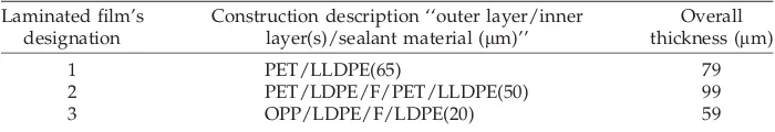
Three samples were used in this study, which are commercial laminated films of various constructions, thickness, and sealant material uses in flexible pack-aging application. In Samples 1 and 2, LLDPE is used as the sealant material, whereas Sample 3 using LDPE. Details on laminated film description are summarized in Table I.
Samples 1 and 2 are manufactured from mono-layer films using the dry-bond process. In this tech-nique, a liquid adhesive (urethanes) is applied to
TABLE I
Description of Laminated Films
Laminated film’s designation
Construction description ‘‘outer layer/inner layer(s)/sealant material (mm)’’
Overall thickness (mm)
1 PET/LLDPE(65) 79
one substrate. It is then dried with hot air. The dried surface is then adhered to a second substrate using heat and pressure. Sample 3 was manufactured using extrusion lamination process. In this process, a thin layer of LDPE was used to bond together two layers of film and foil.
Melting point distribution
In this study, Perkin–Elmer differential scanning cal-orimeter, model DSC-7, was used to study the melt-ing point Tmof the sealing materials. Samples (aged
at room temperature for at least 7 days) of 66 4 mg were prepared and placed in standard aluminum pans, respectively. The samples were scanned at 108C/min scan rate starting at 25–3008C under a he-lium purge gas. Results are summarized in Table II.
Heat flow rate of bar sealing process
The rate of heat conduction Qthrough a plane layer is proportional to the temperature difference across the layer DT and measured thermal conductance C
of the laminated film (Lees’ Disc Apparatus). That is,
Heat flow rate,Q¼CDT (1)
Making of heat-seals
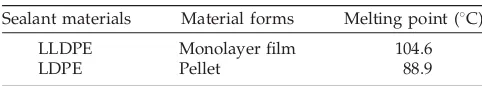
In this project, samples in strip form are prepared for sealing, in which the sealant material was sealed together in the interface to simulate the fin seal form in practice as schematically shown in Figure 1. Lami-nated films are first cut into 15-mm wide strips by Lorentzen and Wettre cutter, made in Sweden. This cutter ensured that clean-cut edges are produced to prevent premature failures in T-peel test.
Heat-seals were made in the laboratory using a model HSG/ETK heat-sealer, made in Germany. This device clamps two pieces of filmstrips between flat, 10-mm wide heated metal bars. The tempera-ture, pressure, and dwell time of the sealing bars are adjustable. Microprocessor-programmed controllers maintained and digitally indicated set temperature for each bar. Both bars were operated at the same temperature in these experiments, and kept closed between sealing to minimize heat loss and tempera-ture fluctuations. The pressure was fixed at two bars
to simulate the most commonly practiced actual industrial condition, whereas platen temperature and dwell time varies. After the heat-seal was made, the sandwich structure was allowed to cool at ambi-ent condition.
Testing of heat-seals
After the heat-seals were produced, it was allowed to condition at room temperature for at least 40 h to achieve chemical stabilization. Aging of heat-seal was necessary as the strength of seal may change in time, which may be due to the memory of polymer, or thermophysical properties of polymer as the heat-seal samples undergo melting and cooling processes. In practice, packaging goods are aged through stor-age before distribution. Thus, heat-seals made in this study were aged for at least 40 h before tested.
The samples were then peeled apart at room tem-perature in tensile tester of model MICRO 350, using a 100 N load cell. Each leg of the test specimen was clamped in the tensile tester. The heat-seal area of the specimen are placed at approximately equidis-tant between the clamps. The specimen is aligned in the clamps so that the seal line is perpendicular to the direction of pull (as shown in Fig. 2). The con-stant rate of loading 300 mm/min with initial jaws separation of 25 mm was chosen as recommended by ASTM F88–85. The maximum force required to tear apart the seal, and failure mode of each pull were recorded.
RESULTS AND DISCUSSION
Heat-seal strength and failure modes
The peeling test measures the forces required to sep-arate a heat-seal after it is allowed to cool. The maxi-mum force per width value obtained in such a test is commonly defined to be the heat-seal strength. All representative values in this article are the average
TABLE II
Melting Point of Sealant Materials Determined Using DSC
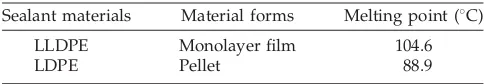
Sealant materials Material forms Melting point (8C)
LLDPE Monolayer film 104.6 LDPE Pellet 88.9
of six. In addition, failure modes at each pulled was carefully examined.
Similar to the results reported by previous researchers,2,4–6 the heat-seal failure of the laminated films was found greatly influenced by its sealing temperature and can be discussed in three stages as following:
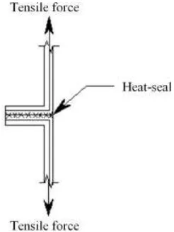
Heat-seal made at temperature substantially lower than the melting point of the sealant mate-rial was found to fail in peeling mode failure. Under this failure mode, disentangles and extri-cates chain ends from the opposite surface occurred, in which the heat-seal bond was peeled apart (Fig. 3). This happened when the strength of the seal is lower than the strength of the lami-nate structures. Hence, heat-seal strength of all samples reported under this failure mode are lower than the strengths reported in other failure modes.
The strength of heat-seal increased gradually with sealing temperature. This is attributed to the
increased of thermal motion (micro-Brownian movement) of chain segments with temperature,4 and therefore, deepen the original zone of diffu-sion and causes a greater peeling force required to peel it apart.
At temperature a few degree Celsius before the final melting point, seal strength increased sharply. Sample failed in either peeling, delami-nating, or tearing mode. Samples may also fail with the combination of delaminating and tearing modes failure. This is the transition region in which failure mode was then changed from peel-ing to delaminatpeel-ing or tearpeel-ing mode failure, or combination of both failure modes. Acceptable heat-seal strength was achieved at this stage.
When sealing was done at plateau initiation tem-perature or greater, all heat-seals are found to have failed under delaminating (Fig. 4) or tearing mode failure (Fig. 5), or combination of both failure modes (Fig. 6). Delaminating mode failure involves tensile break of the heat-seal layer, which is thin and weak, followed by separation of the interlaminar bond. While, tearing mode failure was due to the weaken-ing of the seal at its edge as the material fused, or the weakening of the laminate structures as a result of interlaminar bond separation, plus the geometry of the peel test itself.
After the acceptable seal strength was achieved, no significant increase of seal strength with tempera-ture were found for Sample 3. In contrast, the strength of the seal for Samples 1 and 2 continue to increase gradually with sealing temperature.
The continuously increase of heat-seal strength in Samples 1 and 2 may be due to the decrease of amor-phousness in the LLDPE film. This is because, higher temperature setting deepen the molecular entangle-ment between polymer molecules. Consequently,
Figure 3 Sealing layer torn apart from each other.
Figure 4 The laminated film separated from the sealing layer.
LLDPE chain segments become closely packed, yield-ing a higher degree of crystallinity in the molecular structure. Therefore, higher strength is obtained since polymer with higher crystallinity offer greater physi-cal strength.11
Failure modes of heat-seal had a close relationship with its strength. As mentioned above, heat-seal failed in peeling mode failure having relatively lower strength due to only a slight molecular entan-glement between polymer molecules in the interfa-cial zone. Therefore, heat-seal can easily be peeled apart before any failure occur to the laminate struc-tures which are relatively stronger than the heat-seal with only slight molecular entanglement.
As platen temperature increased, deeper molecular entanglement between polymer molecules in the interfacial zone occurred. Thus, the heat-seal strength increased subsequently as the depth of mo-lecular entanglement increased.
Up to a certain level, when the strength of the heat-seal exceeded the strength of the interlaminar bond, the laminate structures separated from the sealing layer instead of peeling of the heat-seal, and leaving that portion and the other laminated film intact (Fig. 4). Hence, heat-seal strength reported in delaminating mode failure was relatively higher than the heat-seal strength reported in peeling mode failure.
In addition to the increase of heat-seal strength, the increase of platen temperature also increased the strength of the interlaminar bond. However, under marginal condition, uneven strengthening of inter-laminar bond on heat-seal area occurred. Laminated films tested failed in the combination of delaminat-ing and teardelaminat-ing modes failure. In these failure modes, the laminated film was first separated into monolayer structures at the peel line. When come to the area in which uneven strengthening of interlami-nar bond occurred, the monolayer structure broke simultaneously after delaminating, due to the uneven tensile stress distribution (Fig. 6) at the heat-seal area.
When heat-seals are made at a higher platen tem-perature after obtaining the combine failure modes, the strength of the interlaminar bond has been strengthened evenly at the heat-seal area. Laminated film tested was then failed in tearing mode failure. This is because the strength of the laminate struc-tures (monolayer films) are now relatively lower than the strength of the interlaminar bond and the heat-seal. Under this failure mode, the laminated film broke just at the edge of the heat-seal (Fig. 5). Heat-seal strength achieved under this failure mode is the highest when compared with heat-seal strength reported under other failure modes.
Effect of platen temperature and dwell time
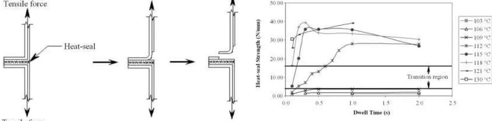
Figure 7 shows the effects of dwell time on heat-seal strength at different platen temperature for Sample 1. At temperatures substantially lower than the melt-ing point of the sealant material, no effects of dwell time on heat-seal strength is observed. The lowest activated temperature of this sample was 1128C. As may be seen, heat-seal strength changes with dwell time at this temperature setting. For instance, the heat-seal strength increased from 0.13 to 1.86 N/mm when sealed with dwell time setting of 0.1 and 1 s, respectively. This was due to the transient change in the interfacial temperature with time. After 1 s, no effect of dwell time on heat-seal strength was
Figure 5 Breaking of the laminated film just at the edge of the seal.
Figure 6 Combination of delaminating and tearing modes.
detected, because the steady-state interfacial temper-ature had been achieved.
At relatively higher platen temperature, the effect of dwell time on heat-seal strength was even greater. For example, at 1158C, 0.2 s was required to achieve an acceptable heat-seal strength. However, this can be achieved at 0.1 s when sealing is made at 1188C or higher.
Similar results are reported for Sample 2. As may be seen in Figure 8, acceptable heat-seal strength was achieved at 0.4 s, when sealed at lowest acti-vated temperature of 1188C. However, this can be achieved at a faster speed when sealing was made at a higher temperature setting.
Notable that the heat-seal strength of all sample were slightly decreased at all temperature setting when sealed at 1 s or longer. This may due to the weakening of the seals as it had been pressed in between the heated bar at the molten state, which reduces the thick-ness of the seals. This may also be caused by the decrease of material properties when exposed to tem-perature at a relatively longer period of time. The decrease of heat-seal strength may not be significant though, it is however, recommended that the dwell time should not be set longer than 1 s as this will bring no beneficial effect on the heat-seal strength.
The study of heat-seal strength beyond 1 s of dwell time is only of theoretical interest. In practice, the setting of dwell time will not be longer than 1 s as most of the packaging machine is operating at very high speed.
Figure 9 shows the effect of heat-seal strength on dwell time at various platen temperatures for Sam-ple 3. As shown in the graph, heat-seal strength was dependent mainly on platen temperature. No increase of heat-seal strength with dwell time was detected. This is because the relatively higher ther-mal conductance of the sample allowed the seal to be made at shorter dwell time.
Previous researchers have also confirmed that the main factors affecting heat-seal strength is the platen temperature. The results of Theller,2who looked at the
effect of dwell time at constant platen temperature, indicated that the heat-seal strength is a strong func-tion of platen temperature and is not dependent on dwell time beyond 0.4 s for LDPE film sealed at 106 and 1108C. In addition, Yasuo6 stated that tensile fail-ure which occurred inside the heat-seal is more sensi-tive to sealing temperature. Meka and Stehling3 also reported that heat-seal strength depends primarily on plated temperature and secondary on dwell time.
Effect of platen pressure
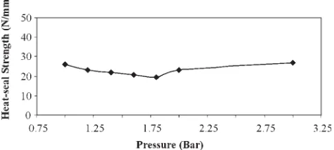
Meka and Stehling3 reported that platen pressure has no measurable effect on heat-seal strength. Only a small level of pressure was required to bring the surface into contact. In this study, the effect of platen pressure on heat-seal strength was investigated on Sample 1. The platen temperature of 1138C was used. As may be seen in Figure 10, no significant change of heat-seal strength with platen pressure was found. These confirmed the results reported by the previous researchers.
Heat-sealing curve
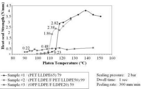
Heat-seal strength versus platen temperature curves at dwell time setting of 1 s are shown in Figure 11. The heat-sealing curves for all samples were found having
Figure 8 Graph of heat-seal strength versus dwell time at
various platen temperatures for Sample 2. Figure 9time at various platen temperatures for Sample 3.Graph of heat-sealing strength versus dwell
a similar shape to that of the idealized heat-seal strength curve established by Stehling and Meka.4
Heat-sealing curve obtained on Samples 1 and 2 exhibited slightly different with continuously increase of heat-seal strength after the acceptable heat-seal was achieved. Therefore, no plateau region reported as plateau seal strength is defined to be the strength when reaches a constant value.
As shown in Figure 11, heat-seal began to be made at a temperature which was found substan-tially lower then the melting point of the sealing materials. This temperature is called seal initiation temperature, where a measurable but low level of seal strength was achieved.
As platen temperature increased, seal strength increased gradually. At temperature a few degree Celsius before plateau initiation temperature, seal strength increased greatly for Samples 1 and 2. Con-trary, Sample 3 exhibited only little increase of its seal strength. This is attributed to the low achievable plateau seal strength in Sample 3 that is made by extrusion lamination process. The reason is, in extru-sion lamination process, LDPE was used to bond to-gether other substances. However, the intrinsic adhe-sive affinity of LDPE (adheadhe-sive agent of extrusion lamination process) toward other substance is lim-ited.1 Therefore, laminated films made by extrusion lamination process, such as Sample 3, have relatively low level of achievable plateau seal strength.
Plateau initiation temperature
For all samples, the temperature where the plateau begins (Tpi) corresponds closely to the final melting
point (Tmf) of their sealant materials. This was shown
in Figure 12, where the Tpi is plotted againstTmf for
both samples. The straight line in this figure is the locus Tpi ¼ Tmf, and all points fall closely to this
locus.
Sample 3 that used LDPE as the sealant material required Tpi to be set 188C higher then the Tmf,
whereas, Samples 1 and 2, which use LLDPE as the sealing material, Tpi required to be set about 108C
higher then the Tmf.
Thermal conductance
Thermal conductance of each sample was measured using the Lees’ Disc Apparatus method. Results in Table III shows that Sample 3 have the highest ther-mal conductance, followed by Sample 1 the middle and Sample 2 the lowest.
Heat flow rate
As defined in eq. (1), heat flow rate for conduction state at steady flow condition is proportional to the conductance of laminated films and heat force of the process. Assuming the outer surface temperature of the laminated film rise to the thermal condition of platen temperature at the moment of contact, and is kept at this thermal condition while the interfacial temperature are at room temperature during heat-sealing cycle, and steady heat flow condition occurred, the heat flow rate calculated using eq. (1) for each sample at the plateau initiation temperature setting were as shown in Table IV.
Graph of heat flow rate versus dwell time at the lowest activated temperature (Fig. 13) shows that the dwell time of heat-sealing process corresponds closely with the heat flow rate of the laminated films. Samples with greater heat flow rate were sealed with shorter dwell time because heat flow was faster in those samples.
Figure 11 Graph of heat-seal strength versus platen tem-perature at dwell time of 1 s.
Because heat flow rate is directly proportional to platen temperature and thermal conductance of the laminated film, thus in the case when the use of lon-ger dwell time is not permissible, a higher platen temperature setting can be used to achieve the same flow rate. This is evident in Samples 1 and 2, where
Tpi setting for Sample 2 was 38C higher than Sample
1 when sealed at the same dwell time.
However, it is recommended that laminated films with higher thermal conductance is preferable as it allowed the use of shorter dwell time and lower platen temperature setting. The former have direct impact on the production speed and the latter have less harmful effect on the product and uses lower energy in a long run.
Process windows of bar sealing application
Figure 14 shows the general process window of bar sealing application. The process window can be approximately described by several quantities illus-trated in the figure:
1. The left vertical border, this border indicated the shortest dwell time, which was determined by the minimum possible time setting of the sealing machine. However, this do not limits the practical usage of the process window as almost all the machines having the same limit of 0.1 s, and dwell time required in commercial production rate is commonly longer than 0.1 s. 2. The right vertical border, this border indicated
the longest dwell time suggested in the process window. Longest dwell time of 1 s was selected because all samples exhibited approximately constant value or slight decrease of the heat-seal strength after 1 s dwell time (Figs. 7–9). In practice, dwell time required for commercial production rate is usually at the setting of 0.3–
0.7 s. Hence, 1 s of longest dwell time in the window is sufficient to provide adequate refer-ence for practical usage.
3. The lower border, the lowest activated platen temperature setting for each particular dwell time is revealed in the lower border. Setting fall on this border is the optimum combination of platen temperature and dwell time, because no exces-sive temperature was used under this setting. 4. The upper horizontal border, heat-seal can be
made in a rage of platen temperature setting, however, lower sealing temperature uses less energy, allow the package to be handle quicker, and have less potential effect on the contained product.11 Therefore, higher platen temperature of 158C after the lowest activated temperature setting is selected to be the highest tempera-ture limit of the window. Combination of platen temperature and dwell time after the highest temperature limit is not recommended because it is not efficient.
Figures 15–17 show the process windows of Samples 1–3 respectively. All points drop inside the window are combination of platen temperature and dwell time that produced acceptable heat-seal. Points drop on the lower borderline were optimum combination of platen
Figure 13 Graph of heat flow rate versus dwell time at lowest activated temperature.
TABLE IV
Heat Flow Rate Calculated at the Plateau Initiation Temperature
Laminated film designation
Construction description ‘‘outer layer/inner layer(s)/sealant material (mm)’’
Heat flow rate (1105W/m2)
1 PET/LLDPE(65) 1.257
2 PET/LDPE/FOIL/PET/LLDPE(50) 1.321 3 OPP/LDPE/FOIL/LDPE(20) 1.367 TABLE III
Thermal Conductance of Laminated Films Determined Using Lees’ Disc Apparatus
Sealant materials Material forms Melting point (8C)
temperature and dwell time, because no excessive temperature was used.
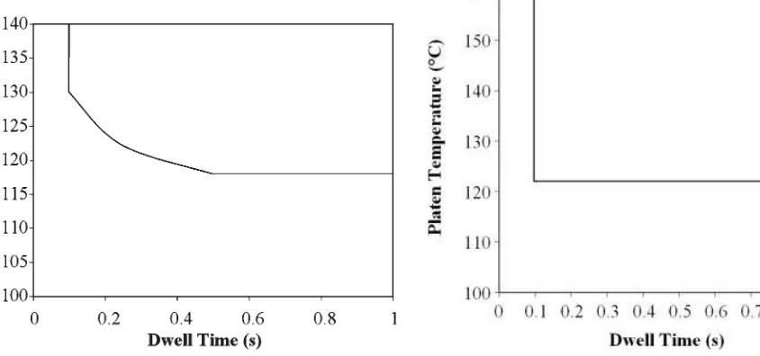
In many cases, a form/fill/seal machine used to produce the heat-seal packages was set to run at a desired production speed, and so dwell time is vir-tually a given. Hence, process window become a very helpful guide to provide information about which platen temperature to be used to produce an acceptable heat-seal at the optimum condition. For example, suppose Sample 2 is to be used, and the machine is to be run at the dwell time setting of 0.3 s, the optimum platen temperature setting would then be at 1218C (Fig. 16). However, in some cases, high production rate is not required which might be due to a lower market demand of the products. Thus the machine is designed to run at lower speed incorporated with a longer dwell time. In that case,
the combination of 0.5 s dwell time and 1188C platen temperature can certainly reduce the energy con-sumption by the entire process as lower temperature setting is used.
As illustrated in the bar sealing process windows (Figs. 15–17), a very short dwell time of 0.1 s can be used while combined with a very high temperature. However, care should be taken while selecting the material for the outer construction of the laminated film, because the outer surface of the laminated film would be contacted directly to the heated bar. There-fore, materials of higher melting point should be considered to avoid damage of the seal area, which can occur if the heated bar temperature exceed the melting temperature of the material of the outer con-struction.
Figure 14 General process window of bar sealing applica-tion.
Figure 15 Process window of Sample 1 at 2 bar.
Figure 16 Process window of Sample 2 at 2 bar.
For process window of Sample 3, the lower border of the process windows was form by a horizontal line. This indicated that the acceptable heat-seal could be obtained at any dwell time setting for as long as the activated temperature level has been achieved. As discussed above, shorter dwell time can be used when higher heat flow rate is provided. But unlike other samples, the very short dwell time of 0.1 s can be used at the lowest activated tempera-ture setting for this sample was attributed to its very good thermal conductance. Therefore, laminated films having higher thermal conductance provide better combination of plated temperature and dwell time, which helps to reduce energy consumption in the heat-sealing process, by allowing lower platen temperature setting even though a very short dwell time is used.
GENERAL CONCLUSIONS
The main conclusions that can be derived from the study are as follows:
1. Bar sealing process window for each samples were developed. Information about the opti-mum combination of platen temperature and dwell time for each individual laminated film can be obtained in the respective process win-dows. Thus, optimum machine setting can be predicted when the laminated films are to be used in the real application and machine setting time can be reduced.
2. The effect of bar sealing process variables on heat-seal strength of laminated film has been quantitatively determined. Heat-seal strength was determined primarily by the platen temper-ature, and secondly by dwell time. Higher platen temperature was required to seal lami-nated film having lower thermal conductance. However, shorter dwell time was required if the increase of the platen temperature had increased the heat flow rate of the process. Dwell times of the order of 0.3–0.5 s required for commercial productions rates can be obtained by proper selection of the individual plated temperature. The heat-seal strength is not significantly affected by pressure. However,
some level of pressure is necessary to bring two heated laminated films into intimate contact to effect sealing.
3. The achievable heat-seal strength was also determined by the lamination process used to produce the laminated film, and sealant mate-rial used in the laminated film. Laminated films made from extrusion lamination process pro-vide lower achievable heat-seal strength when compared with the laminated films made from dry-bond lamination process.
4. Platen initiation temperature closely corre-sponds to the final melting point of the sealant materials. To achieve plateau seal strength, laminated films using LDPE and LLDPE as sealant materials required platen temperature to be set slightly higher than the final melting point of the sealant materials. Outer construc-tion with higher melting temperature was pref-erable for laminated film that required to be sealed using higher platen temperature to avoid damage on the outer seal area.
5. Strength of heat-seal and its failure modes are closely related. Heat-seal strength achieved under tearing mode failure is the highest, fol-lowed by heat-seal strength achieved under delaminating mode failure, and the heat-seal strength achieved under peeling mode failure is the lowest.
References
1. Brody, A. L.; Marsh, K. S, Eds. The Wiley Encyclopedia of Packaging Technology, 2nd ed.; Wiley: United State of Amer-ica, 1997, p 823.
2. Theller, H. W. J Plast Film Sheeting 1989, 5, 66. 3. Stehling, F. C.; Meka, P. J Appl Polym Sci 1994, 51, 89. 4. Stehling, F. C.; Meka, P. J Appl Polym Sci 1994, 51, 105. 5. Tsujii, T.; Tetsuya, T.; Ishiakw, U. S.; Mizoguchi, M.; Hamada,
H. J Appl Polym Sci 2005, 97, 753.
6. Yasuo, H.; Hashimoto, Y.; Ishiakw, U. S.; Leong, Y. W.; Hiroyuki, H.; Tsuju¨, T. Polym Eng Sci 2005, 46, 205.
7. Owens, D. K. J Appl Polym Sci 1975, 19, 265. 8. Farley, J. M.; Meka, P. J Appl Polym Sci 1994, 51, 121. 9. Falla, D. J. The use of ULDPE’s in pouch for packaging
flow-able materials. SPE ANTEC 1994, III, 3141.
10. Halle, R. W.; Davis, D. S. Heat sealing linear ethylene plasto-mers to ionoplasto-mers or LLDPEs. SPE ANTEC 1995, 1, 2.