DESIGN OF AN INTELLIGENT SWITCH FOR
LOW VOLTAGE DISTRIBUTION SYSTEM
ABU KHIR BIN ABU BAKAR
APPROVAL
“ I hereby declared that I have read through this report and found that it has comply
the partial fulfillment for awarding the degree of Bachelor of Electrical Engineering (Industrial Power).
Signature :
Supervisor’s Name : Prof. Madya Dr. Musse Mohamud Ahmed
DESIGN OF AN INTELLIGENT SWITCH
FOR LOW VOLTAGE DISTRIBUTION SYSTEM
ABU KHIR BIN ABU BAKAR
This Report Is Submitted In Partial Fulfillment Of Requirements For The Degree
Of
Bachelor In Electrical Engineering (Industrial Power)
Faculty of Electrical Engineering
Universiti Teknikal Malaysia Melaka
DECLARATION
I hereby declared that this report entitled “ DESIGN OF AN INTELLIGENT SWITCH FOR LOW VOLTAGE DISTRIBUTION SYSTEM “ is the result of my own work
except for the excerpts that have been cited clearly in the references.
Signature :
Author’s Name : Abu Khir b. Abu Bakar
iii
ACKNOWLEDGEMENTS
ABSTRACT
This project is to design an Intelligent Switch for Low Voltage Distribution. This project used the knowledge of electrical and electronics. This project has 2 main parts of circuits, which are step-down AC voltage (240 Volt) to DC voltage (9 Volt). The second part is as emergency supply which alerts for darkness condition and no power supply is needed. For the step-down voltage part, it converts high voltage to low voltage (240 V to 9 V). As been used for this application, I used step-down transformer as main equipment. And for other equipment as bridge rectifier, capacitor, two changeover contacts (relay normally closed). And for the emergency supply part, is to analyze the performance of the system in darkness and no power supply condition. For analyze the performance in darkness condition, it used phototransistor. In this section have a Darlington pairs (2 NPN transistors) and relay. Others objectives is to determine the characteristics of the phototransistor. For the last objectives is to provide education materials for students such as experiments or study case model. During completed this circuit, I have apply many skill from my study.
v
ABSTRAK
TABLES OF CONTENTS
List of Abbreviations, Symbols, Specialized Nomenclature xi
I INTRODUCTION
2.1 Constructing a Universal Power Supply 5
2.2 Fundamental Phototransistor Circuits 8
2.3 Making a Light and Dark Sensor 9
2.4 Light Detection Using a Phototransistor 10
vii
4.1 Function of Components 29
LIST OF TABLES
TABLE TITLE PAGE
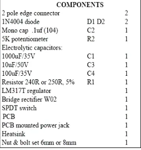
2.1 Universal Power Supply Parts List 7
3.1 Project Planning 28
xi
°F - Fahrenheit, unit of temperature
BATT - Battery
TNB - Tenaga Nasional Berhad
R - Resistor
C - Capacitor
CHAPTER 1
INTRODUCTION
1.1 Project Background
This is intelligent simple switch circuit which enables automatic switching on of an emergency light system during darkness in the event of mains failure. The mains power failure condition is detected by the section consisting of mains step-down transformer X1 followed by bridge rectifier comprising diodes D1 through D4 and smoothing capacitor C1. If the main is available then it causes the relay RL1 to energize which has two sets of changeover contacts. The light/darkness condition is detected by the circuit comprising phototransistor FPT100/2N5777 followed by Darlington pair comprising transistors T2 and T3.
2
As a result, relay R2 gets energized. Thus, it would be observed that when mains is absent (relay RL1 de-energized) and it is dark (relay RL2 energized), the switch output path is complete. In any other condition switch output path would get broken. The switch output terminals can be used (in series with supply) to control a lighting system directly or indirectly through another contractor/heavy-duty relay depending upon the load.
1.2 Problem Statement
Before make any project or big plan, I must make some research from all community which is can solve any problem for people. By creating new technology or equipment, its can make more effective and simple life for all human. In my research, my focus is equipment that related my course study (power industry).
About 2 weeks, I found that many work only can be done when has current or
power supply. When don’t have any power throw the circuit, many work cannot be
completed such as operated in switchgear which is used relay as important equipment. As basic, we look that relay just small equipment in switchgear but the function is very important.
After that, I plan to the intelligent switch which is has step-down transformer and phototransistor. This is new technology which can operate when there is no main power
supply and in the darkness condition (don’t have light).
It’s function just like an emergency circuit as usual but has some adjustment in
1.3 Objectives
For all projects must have a objectives. Its can make the overview of project more details and focus what must be done to achieve the objectives. I already listed three main objectives for my final year project which can guide me during do all working progress.
Firstly, my main objective is to design an intelligent switch for low voltage distribution system. In this circuit, it can convert high voltage to low voltage (230V to 9V). For have this application, I must used step-down transformer as main equipment. And for other equipment as bridge rectifier, capacitor, two changeover contacts (relay normally closed).
Secondly, my main objective is to analyze the performance of the system in darkness and no power supply condition. For analyze the performance in darkness, it used phototransistor. In this section have a Darlington pairs (two NPN transistors) and relay.
Others main objective is to determine the characteristics of the phototransistor. For the last objectives is to provide education materials for students such as experiments or study case model. During completed this circuit, I have apply many skill from my study.
1.4 Scope of the Project
4
The scope of this project is the application for user such as Petronas or Tenaga Nasional Berhad (TNB) that used the relay in switchgear. The relay must have in switchgear as protection and backup power supply until have permanently supply.
Based on my research, the relay must be in the on condition which is always has power supply through it. Relay act as important equipment in switchgear. When relay
don’t have any power supply, its contact will be changeover to other side such as used normally closed relay. In no power supply condition, the contact will be at closed contact (depends on the circuit which is in open or closed circuit).
CHAPTER 2
LITERATURE REVIEW
2.1 Constructing a Universal Power Supply [9]
This is a basic, text-book, Universal Power Supply voltage regulator circuit using an LM317, 3-terminal regulator in a TO-220 package. The Universal Power Supply output voltage can be set to anywhere in the range 1.5V to 30V by selecting two resistances. By using a potentiometer, R2, as one of the resistors you can dial up the output voltage wanted. Either AC or DC input can be supplied to the PCB via a socket or terminal block. Connection can be either way around. This is because we have provided a bridge rectifier on board. The input DC voltage to the regulator must be at least 2.5V above the required output voltage. An off/on switch is provided.
6
When external capacitors are used with any IC regulator it is good practice to add protection diodes to prevent the capacitors discharging back into the regulator in the event of abnormal operating conditions, like a sudden short circuit on the input or the output, or a back emf from an inductive load. That is the function of D1 and D2.
The value of R1 can range anywhere from 120R to 1200R (see Data Sheet on www.ti.com) However, circuits from most other sources settle on using either 220R or 250R. We have used 240R or 250R. The voltage drop across R1 is 1.25V for all values, and this is the key to the design. 1.25V is the reference voltage of the regulator.
Whatever current flows through R1 also flows through R2, and the sum of the voltage drops across R1 and R2 is the output voltage. (Additional current Id also flows in R2 but it is typically 50uA so is negligible.)
The design formula is:
VOUT = 1.25 (1 + R2/R1) volts, or alternatively R2/R1 = (VOUT/1.25) – 1
Figure 2.1: Universal Power Supply Schematic Diagram
8
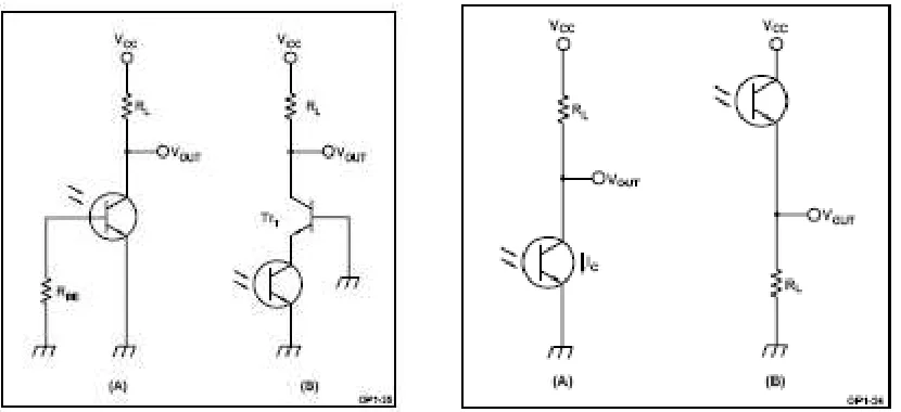
2.2 Fundamental Phototransistor Circuits [10]
Figures 9 and 10 show the fundamental phototransistor circuits. The circuit shown in Figure 9 (A) is a common-emitter amplifier. Light input at the base causes the output (VOUT) to decrease from high to low. The circuit shown in Figure 9 (B) is a common-collector amplifier with an output (VOUT) increasing from low to high in response to light input. For the circuits in Figure 9 to operate in the switching mode, the load resistor (RL) should be set in relation with the collector current (IC) as VCC < RL × IC.
The circuit is shown Figure 10 (A) uses a phototransistor with a base terminal. A RBE resistor connected between the base and emitter alleviates the influence of a dark current when operating at a high temperature. The circuit shown in Figure 10 (B) features a cascade connection of the grounded-base transistor (Tr1) so that the phototransistor is virtually less loaded, there are by improving the response. This phototransistor is sensitive to normal visible light (800 nm). Infrared phototransistors can be used, but won't be as sensitive to flashlights and other household sources.
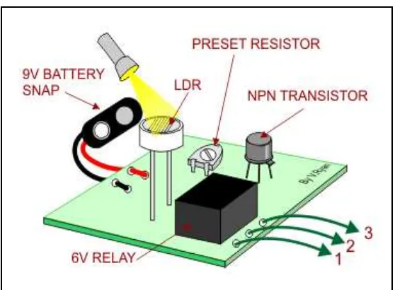
2.3 Making a Light and Dark Sensor [11]
Figure 2.3: Circuit of Light and Dark Sensor
Figure 2.4: Diagram of circuit Light and Dark Sensor
10
2.4 Light Detection Using a Phototransistor [12]
This page describes an example project that turns on a red LED when light is dim and a green LED when light is bright. Or more to the point, changes color when objects (such as a fan blade) pass in front of it.
Because the lighting required to enable either LED is controlled by individual potentiometers, they can be set such that either, neither or both LEDs turn on. That is, the red LED doesn't have to turn on simply because the green LED turned off.
This is also a good example of how to use a phototransistor, rather than a cadmium sulfide photocell to detect light. Phototransistors react much more quickly, and are much more sensitive. Couldn't you create a simple robot that seeks light (or dark) by turning on motors rather than LEDs?
2.4.1 Application of the Project
For a prototype hand held tachometer project, a microcontroller analyzed a phototransistor and a pair of potentiometers using three built-in analog-to-digital (ADC) converters. Unfortunately, that design required the microcontroller to spend most of its time reading the phototransistor's voltage in order to detect a passing line or mark.
If your project requires a microcontroller, but the microcontroller doesn't have any available ADCs, perhaps adding a comparator chip would provide a faster, less expensive solution.
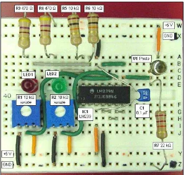
Figure 2.5: Light Detector Circuit
2.4.2 Function of the Components
1) U1