ANALYSIS OF BACK-FLASHOVER RATE FOR 132KV OVERHEAD TRANSMISSION LINES
MUHAMMAD SADIQ BIN SUHAIMI BACHELOR OF ELECTRICAL ENGINEERING
“I hereby declare that I have read through this report entitle “Analysis Of Back-Flashover Rate For 132kv Overhead Transmission Lines” and found that has comply the partial fulfilment for awarding the degree of Bachelor of Electrical Engineering (Industrial Power)”
Signature : ………..
ANALYSIS OF BACK-FLASHOVER RATE FOR 132KV OVERHEAD TRANSMISSION LINES
MUHAMMAD SADIQ BIN SUHAIMI
A report submitted in partial fulfillment of the requirements for the degree ofElectrical Engineering (Industrial Power)
Faculty of Electrical Engineering
UNIVERSITI TEKNIKAL MALAYSIA MELAKA
I declare that this report entitle “Analysis Of Back-Flashover Rate For 132kv Overhead Transmission Lines” is the result of my own research except as cited in the references. The report has not been accepted for any degree and is not concurrently in candidature of any other degree.
Signature : ………..
Specially dedicated to my beloved mother and father, my brother, my sister and all my friend. Thank you for all of the support and encouragement during my journey to gain
ACKNOWLADGEMENT
In the name of Allah S.W.T, Most Gracious Most Merciful, With His Grace is blessed upon all other Muslim and human being well. Firstly, I would like to extend the special and greatest gratitude to the supervisor, Pn. Nur Zawani binti Saharuddin from the Faculty of Electrical Engineering, Universiti Teknikal Malaysia Melaka (UTeM) for her guidance, advice and spend time during completion of final year project.
Besides that, also not forget to say a lot of thanks especially to Pn. Aine Izzati binti Tarmizi of providing guidance and assistance and also to Pn. Junainah binti Sardi and other lecture that gives their opinion and suggestion in completing this project.
ABSTRACT
Transmission line is a transmission system that delivers electric power supply from one place to another. In Malaysia, there are two types of transmission line which are single circuit line and double circuit line. Whenever lightning strikes the transmission line, there are possibilities of flashover to occur. The reason is, once lightning strike, the voltage that carried is forced down towards the insulator. The insulator prevents the overvoltage to flowing from the tower to the phase line. However, if this overvoltage equal or exceed the line Critical flashover (CFO) rate, flashover occurs. This phenomenon is known as backflash or back-flashover. During the phenomenon, the back flashover rate (BFR) had been calculated to do the analysis in improving the transmission line performance. The lowest value of BFR indicates that the line is well shielded and can sustain from the surge overvoltage and vice versa. There are several factors that influence the back-flashover rate such as ground flash density, surge impedances, coupling factors, heights of the tower, horizontal separation of ground wires and CFO. Basically, BFR can be calculated by using 3 different methods; simplified, CIGRE and IEEE method. For this project, both simplified and CIGRE methods are used to determine the BFR. Programs are created based on these two methods using GUI, MATLAB software for user-friendly purpose. In the completion of this dissertation, several steps had been taken which are doing research and find information that related to the project through out resources of internet and books, analyze and compare the method of BFR calculation, design and build program by MATLAB (GUI), compare result from program with the result from book and do the conclusion & suggest future recommendation. For the result of this dissertation, it show that the programs that had been built are approved to be used.
ABSTRAK
TABLE OF CONTENTS
CHAPTER TITLE PAGE
ACKNOWLADGEMENT i
ABSTRACT ii
TABLE OF CONTENTS iv
LIST OF FIGURE viii
LIST OF TABLE ixi
LIST OF ABBREVIATIONS Viii
LIST OF SYMBOL Ix
1 INTRODUCTION 1
1.1 Project Background 1
1.2 Problem Statement 2
1.3 Project Objective 2
1.4 Project Scope 3
2 LITERATURE REVIEW 4
2.1 Introduction 4
2.2 Insulation Coordination 4
2.2.1 System Overvoltage 5 2.2.2 Insulation Withstand Characteristics 6 2.2.3 Standard Basic Insulation Levels (BIL) 6 2.2.4 Characteristics of Insulation Coordination 7
2.3 Lightning 7
2.3.1 Formation of Lightning 10
2.4 Lightning Flashes 12
2.5 Backflashover 13
2.6 The Back-flashover Rate (BFR) 15
2.7 The Simplified Method 16
2.9 Different Between Simplified & CIGRE Method 19
3 METHODOLOGY 21
3.1 Introduction 21
3.2 MATLAB Software 21
3.3 Graphical User Interface (GUI) 22
3.4 Simplified Method 23
3.5 CIGRE Method 24
3.6 Methodology Chart 26
3.6.1 Literature Reivew 27
3.6.2 Analyze Method 27
3.6.3 Project Design Development 27
3.6.4 Analyze Program 27
3.6.5 Result & Discussion 28
3.6.6 Conclusion & Recommendation 28
3.6.7 Write Final Report 28
4 PROJECT DESIGN & DEVELOPMENT 29
4.1 Introduction 29
4.2 Create Program With MATLAB, GUI 29
4.3 The Simplified Method 32
4.4 The CIGRE Method 33
5 RESULTS & DISCUSSION 34
5.1 Introduction 34
5.2 Simplified Method 34
5.2.1 Result From A. R. Hileman Book 35
5.2.2 Result From Program 36
5.2.3 Analyze Results 38
5.3 CIGRE Method 39
5.3.1 Result From A. R. Hileman Book 40
5.3.2 Result From Program 42
5.4 Analyze TNB Transmission lines with CIGRE Method Program
51
5.4.1 Ground Flash Density, Ng 52
5.4.2 Result 53
6 CONCLUSION & RECOMMENDATION 54
6.1 Conclusion 54
6.2 Recommendation 54
REFERENCES 55
LIST OF FIGURE
FIGURE TITLE PAGE
2.1 Types of overvoltage 5
2.2 Number of days with thunderstorm,Td in Malaysia 8
2.3 Cloud-to-ground downward negative lightning 8
2.4 Cloud-to-ground downward positive lightning 8
2.5 Ground-to-cloud upward negative lightning 9
2.6 Ground-to-cloud lightning upward positive 9
2.7 Double exponential lightning current waveform 10
2.8 Formation of a stepped leader that starts a lightning strike 11
2.9 Return stroke initiation and propagation. 11
2.10 Illustration of a backflashover. 13
2.11 Installing Shield wire Simulation using FLASH software 14
2.12 The backflashover mechanism 14
3.1 The version of MATLAB that use in this project. 21
3.2 Flow diagram to calculate the BFR by simplified method 23 3.3 Flow diagram to calculate the BFR by CIGRE method 25
3.4 Methodology chart. 26
4.1 Representation to get start in MATLAB GUI after ‘gui’ or ‘GUIDE’ button is selected or clicked.
29
4.2 Blank layout area 30
4.3 The four component are drawn to the layout 30
4.4 The example layout after editing the ‘string’ of each component. 31 4.5 The command part of the ‘calculate’ box on ‘M-file’. 31
4.6 The Simplified Method program. 32
4.7 The CIGRE Method program. 33
5.1 The results shown by A. R Hileman book. 35
Simplified method program.
5.3 The results that are shown from the Simplified Method program. 36 5.4 Graph of the comparison between the book result and program
result.
38
5.5 Data of 115-kV single circuit line had been typed into the CIGRE method program.
42
5.6 Results that had been shown by the CIGRE Method program. 42
5.7(a) Graph of critical current for phase A 45
5.7(b) Graph of critical current for phase B 45
5.7(c) Graph of critical current for phase C 46
5.8(a) Graph of Back-flashover rate for phase A 49
5.8(b) Graph of Back-flashover rate for phase B 49
5.8(c) Graph of Back-flashover rate for phase C 50
5.9 132kV transmission line 51
LIST OF TABLE
TABLE TITLE PAGE
2.1 Classes and types of overvoltage-Standard voltage shapes and Standard Withstand tests
7
2.2 Typical coordination of insulation system voltage 5 2.3 Different between Simplified & CIGRE method. 19 5.1 The value of Critical current, Ic and Tower footing resistance new,
Rinew from the list box of the computer program during the iteration
process.
37
5.2 Comparison between the result from book and program. 38
5.3 Results from A. R. Hileman book. 40
LIST OF ABBREVIATIONS
UTeM - Universiti Teknikal Malaysia Melaka
BFR - Back Flashover Rate
CIGRE - International Council on Large Electric Systems
IEEE - Institute of Electric and Electronic Engineers CFO - Critical Flashover voltage
LIST OF SYMBOL
NL - the number of strokes
P(Ic) - the probability of a flashover
Ic - critical current above which flashover occurs. Ng - The ground flash density (flashes / km2 –year) h - The tower height, meter.
Sg - The horizontal distance between the ground wires, meter.
C - Coupling factor.
VPF - Operating voltage, peak value.
Re - Combination of shield-wire surge impedance and R. Zg - Surge impedance of the ground wires, ohms.
CFONS - Non-standard critical flashover voltage. CFO - Critical flashover voltage.
τ - Time constant of tail, µs. Ts - Travel time of a span, µs.
IR - Current through footing resistance, kA. Ri - Tower footing resistance (ohm).
Ro - Tower footing resistance at low current (non-ionized soil). Ig - Current required to cause soil breakdown gradient.
�� - soil resistivity (ohm-meter)
�� - soil ionization gradient (about 300 kV/m)
CA - coupling factor per phase A.
tf - time to crest of the stroke current, µs. KTT - Tower-top voltage in p.u stroke current. TT - Travel time of a tower, µs.
KTA - Voltage at point A pu stroke current. TA - Travel time to point A on tower, µs. KSP - Span factor, reduces crest voltage at tower.
LIST OF APPENDICES
APPENDIX TITLE PAGE
A Coding of The Simplified Method Program 58
B Coding of The CIGRE Method Program 62
CHAPTER 1
INTRODUCTION
1.1 Project Background
Lightning strike is the one of the natural event. Normally, lightning will strike to the highest of things from ground such as a tower. From the electrical view, this event will be focus on the overhead transmission lines with their tower. This is because when the lightning strikes to the transmission line, it will interfere the efficiency of transferring energy from one site to the others. In terms of electrical, lightning strike on overhead transmission line can be divided into three categories such as lightning strike on the tower, shield wire and phase wire of the transmission line.
1.2 Problem Statement
The back-flashover rate (BFR) is the probability of a flashover, P(Ic) times the number of strokes, NL. However, it is not easy to calculate the value of BFR. Hence, the problem faced is there are difficulties to calculate the BFR value manually. This project just focuses on simplified method and CIGRE method only. The simplified method cannot precisely calculated BFR value for a tower that exceeded 70 meter of height. However, the CIGRE method can accurately calculate BFR value, but it is not appropriate to be done manually due to long of iteration calculation. Hence, computer are required to calculate the BFR value.
1.3 Project Objective
There are three objectives that needs to be achieved during this project :
i. To calculate the BFR value.
ii. To study and analyze the ‘Simplified’ and CIGRE method to calculate the BFR value.
1.4 Project Scope
This project focus on following requirement :
• Type of transmission lines : - Single circuit line (132kV) • Method to calculate the BFR value :
- Simplified method. - CIGRE method.
CHAPTER 2
LITERATURE REVIEW
2.1 Introduction
This chapter highlights the past studies that related to this project and bring as the background theory.
2.2 Insulation Coordination
The term insulation coordination is the process to determine the proper insulation level of several components in the transmission line as well as their placement on the system where it would result in the least damage [1]. It is the selection of an insulation structure that will withstand voltage stresses to which the system or equipment will be subjected to together with the proper surge arrester to reduce frequency of supply interruptions and component failure. The process is determined from the known characteristics of voltage surges and the characteristics of surge arresters.
According to the IEEE Standard (1996), the definition of Insulation coordination is the “selection of insulation strength consistent with the expected overvoltage to obtain an acceptable risk of failure” [2].
Insulation coordination study is determined by the following [3]:
• System over voltages, wave shapes, peak voltage values and probabilities of occurrence.
• The insulation levels of various equipments in a substation are coordinated to protect the equipment such as transformer.
2.2.1 System Overvoltage
There are 3 types of overvoltage extracted from IEC60071-1(2004) which are lightning overvoltage, switching overvoltage, temporary overvoltage in Figure 2.1 shows graph �.�. voltage versus duration of overvoltage occurs [1].
Figure 2.1 Types of overvoltage [4]
Table 2.1 concludes the types and typical shapes of over voltages and its withstanding tests.
2.2.2 Insulation Withstand Characteristics
The insulation withstand of an insulation coordination can be determine by two difference characteristic that is the voltage/clearances or the voltage/time characteristics [1].
• Voltage/Clearance Characteristics
- Withstand voltage as a function of gap spacing for lightning and switching surges.
• Voltage/Time Characteristics
- Withstand voltage as a function of time to crest of the voltage surge
2.2.3 Standard Basic Insulation Levels (BIL)
In IEC Publication 71(1993), Standard Basic Insulation Levels (BIL) is the electrical strength of insulation expressed in crest of standard in crest of “Standard lightning impulse”[5]
There are two types of BIL [1]:
i. Statistical BIL is crest of standard lightning impulse for which insulation exhibits 90% probability of withstand and the probability of flashover or failure is 10% per impulse application. The BIL is standard deviation below the CFO, the BIL equation (2.1)
BIL=CFO[1−1.28(��/���)] (2.1)
Where,
σf = Critical flashover voltage, CFO in �.�. CFO = Critical flashover voltage, CFO.
2.2.4 Characteristic of Insulation Coordination
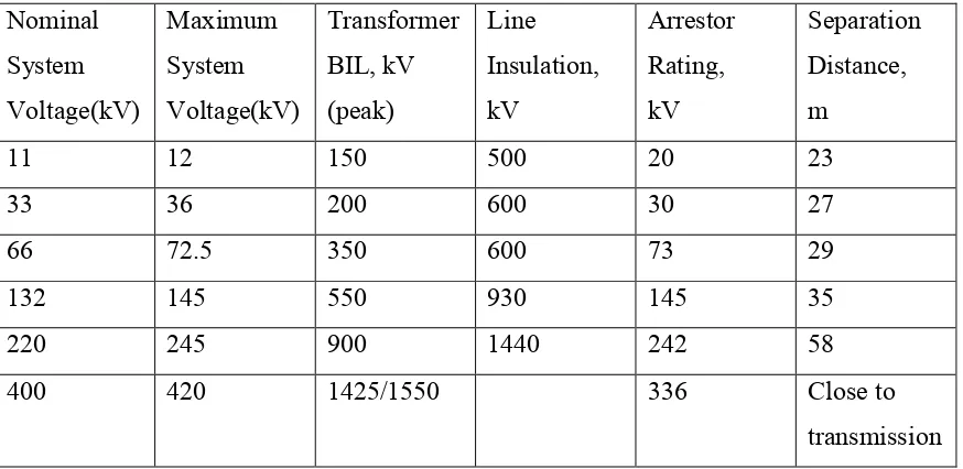
Table 2.2 stated the characteristics a typical coordination of insulation for some system voltages together with the corresponding line insulation in High engineering-J R Lucas (2001) [6].
Table 2.2 Typical coordination of insulation system voltage Nominal System Voltage(kV) Maximum System Voltage(kV) Transformer BIL, kV (peak) Line Insulation, kV Arrestor Rating, kV Separation Distance, m
11 12 150 500 20 23
33 36 200 600 30 27
66 72.5 350 600 73 29
132 145 550 930 145 35
220 245 900 1440 242 58
400 420 1425/1550 336 Close to
transmission
2.3 Lightning
Lightning is an atmospheric electrostatic discharge (spark) accompanied by thunder, which typically occurs during thunderstorms, and sometimes during volcanic eruptions or dust storms which measure in kilometer[7].