i
QUADCOPTER EMBEDDED CONTROLLER FOR ALTITUDE HOLD AND SURVEILLANCE
AHMAD HAFIZI BIN ZURIADI
This report is submitted in partial fulfillment of the requirements for the award of the Bachelor of Electronic Engineering (Industrial Electronics) With Honours
Faculty of Electronic and Computer Engineering Universiti Teknikal Malaysia Melaka
ii
UNIVERSTI TEKNIKAL MALAYSIA MELAKA
FAKULTI KEJURUTERAAN ELEKTRONIK DAN KEJURUTERAAN KOMPUTER
BORANG PENGESAHAN STATUS LAPORAN
PROJEK SARJANA MUDA II
Tajuk Projek :
QUADCOPTER EMBEDDED CONTROLLER FOR ALTITUDE HOLD AND SURVEILLANCE
Sesi Pengajian : 1 1 / 1 2
Saya AHMAD HAFIZI BIN ZURIADI mengaku membenarkan Laporan Projek Sarjana Muda ini disimpan di Perpustakaan dengan syarat-syarat kegunaan seperti berikut: 1. Laporan adalah hakmilik Universiti Teknikal Malaysia Melaka.
2. Perpustakaan dibenarkan membuat salinan untuk tujuan pengajian sahaja.
3. Perpustakaan dibenarkan membuat salinan laporan ini sebagai bahan pertukaran antara institusi pengajian tinggi.
4. Sila tandakan ( √ ) :
SULIT* *(Mengandungi maklumat yang berdarjah keselamatan atau kepentingan Malaysia seperti yang termaktub di dalam AKTA RAHSIA RASMI 1972)
TERHAD** **(Mengandungi maklumat terhad yang telah ditentukan oleh organisasi/badan di mana penyelidikan dijalankan)
TIDAK TERHAD
Disahkan oleh:
__________________________ ___________________________________
(TANDATANGAN PENULIS) (COP DAN TANDATANGAN PENYELIA)
iii
“I hereby declare that this report is the result of my own work except for quotes as cited in the reference.”
Signature : ………
iv
“I hereby declare that I have read this report and in my
Opinion this report is sufficient of the quality for the award of Bachelor of Electronic Engineering (Electronic Industrial) With Honors.”
Signature : ………
v
vi
ACKNOWLEDGEMENT
Alhamdulillah, all praise to Allah the Most Beneficent and the Most Merciful, who has taught what I knew not. It is the grace of the Almighty Allah that this research work has been completed successfully on time.
First and foremost, I would like to take this opportunity to thank my project supervisor, En. Muhammad Noorazlan Shah bin Zainudin for this invaluable guidance, assistance and support throughout the project. Under her supervision, many aspects regarding on this project has been explored and with the knowledge, idea and support received from him, this thesis can be presented in the time given. For all lecturer involved in teaching my course, thanks for the lesson that been delivered.
vii
ABSTRACT
viii
ABSTRAK
ix
TABLE OF CONTENTS
CHAPTER TITLES PAGE
PROJECT TITLE i
PROJECT STATUS FORM ii
DECLARATION iii
APPROVAL iv
DEDICATION v
ACKNOWLADGEMENT vi
ABSTRACT vii
ABSTRAK viii
CONTENTS ix
LIST OF TABLE xii
LIST OF FIGURE xiii
1 INTRODUCTION 1
1.1 Introduction 1
1.2 Objectives Of Project 2
1.3 Problem Statement 3
1.4 Scope Of Project 3
1.5 Project Planning 3
1.6 Thesis Outline 4
2 LITERATURE REVIEW 5
2.1 Microcontroller 6
2.2 Board Arduino Duemilanova 8
2.3 Brushless Outrunner Motor 9
2.4 Electronic Speed Control 11
x
2.6 Remote control transmitter receiver 13
2.7 Ultrasonic Range Finder 14
2.8 Propeller 15
2.9 EasyCap device 16
3 PROJECT METHODOLODY 18
3.1 Data Collection Method 19
3.2 Flow Chart Methodology 20
3.3 Project Planning 22
3.4 Print the circuit on PCB 25
3.5 Etching Circuit 25
3.6 Drilling Process 26
3.7 Drill 26
3.8 Installation the component 26
3.9 Circuit Testing 26
3.10 Soldering Process 26
3.11 The steps to solder the component 27 3.12 Equipment on Soldering Steps 28
4 RESULT AND DISCUSSION 29
4.1 Basic theory aviation 30
4.1.1 Axis Motion 30
4.1.2 Main Control Surface 31
4.2 Flight configuration 32
4.3 Quadcopter Basic Component and Function 33
4.3.1 Embedded Platform 34
4.4 Setup Quadcopter 34
4.4.1 Main Body 34
xi
4.5 Altitude Hold 42
4.5.1 Ultrasonic Range Finder Pin Out 42 4.5.2 Ultrasonic Range Finder Timing 43
4.5.3 Bean Characteristic 44
4.5.4 Altitude Hold Operation 45
4.6 Surveillance System 48
4.7 Maiden Flight Check Out 49
5 CONCLUSION 50
5.1 Conclusion 50
5.2 Suggestion for future work 51
xii
LIST OF TABLES
TABLE NO. TITLE PAGE
1 Microcontroller ATmega 328P Specification 7 2 Turnigy Brushless Motor 2217 Specification 10
3 Part List 33
4 Technical Parameter 33
5 Receiver Channel 35
6 Arming Motor Stick Position 36
7 Disarming Motor Stick Position 36
8 Program Mode 40
9 Set Item Mode Value 41
xiii
LIST OF FIGURES
FIGURE NO. TITLE PAGE
2.0 Atmega 328P Pin Mapping 6
2.1 Arduino Dumilanove 8
2.2 Turnigy Brushless Motor 2217,23A,1050Kv 10
2.3 Turnigy Plush 25A 11
2.4 Flightmax 4400mAH 3S1P,15C 12
2.5 Remote Control Transmitter and Receiver 13
2.6 Long Analog Distance Sensor 14
2.7 Propeller 10x4.5 15
2.8 EasyCap device 16
3.0 Flow Chart of Project Implementation 20
3.1 Software Flow Chart 21
3.2 Gantt Chart for Semester I 22
3.3 Gantt Chart for Semester II 24
4.0 The Orientation Roll, Pitch and Yaw 30
4.1 „+‟ pattern (left) and „x‟ pattern (right) 32
4.2 Aluminum Frame 34
4.3 Normal Startup Procedure 38
4.4 Throttle Range Setting 39
4.5 Connection between Microcontroller
and Ultrasonic sensor 42
4.6 Sensor Sense the Obstacle 43
4.7 Bean Pattern 44
4.8 Distance versus Time 46
1
CHAPTER 1
INTRODUCTION
1.1 Project Overview
2
1.2 Objective of Project
The objective of this project is radically modifies the design of a conventional helicopter. Besides that, this project will create the talent of student to apply their knowledge in this final year project. The objectives are:
To create a light weight Quadcopter
To create a altitude hold function on Quadcopter
To create the Quadcopter that have a capability to take a video for surveillence system
The first objective is to build the unmanned aerial vehicle (UAV) by using the light weight material that can lift by using four rotors and this quadcopter can be using by everyone. Therefore, a design and controller based on a beginner level pilot skill are essential to the project. The second objective is to use the ultrasonic range finder sensors for throttle correction during hover the Quadcopter and hold the Quadcopter on their position. The ultrasonic range finder will do the altitudes hold function by adjusts the throttle and elevator to maintain a target altitude set by user.
3
1.3 Problem Statement
Nowadays, in order to prevent crime issues we have to take precaution to avoid this criminal and take an action to solve this problem. The Quadcopter is a new way to solve this problem by implement the surveillance system to decrease the criminal around the city.
Next, Firefighters are rescuers extensively trained primarily to put out hazardous fires that threaten civilian populations and property, to rescue people from car incidents, collapsed and burning buildings and other such situations. The increasing complexity of modern industrialized life with an increase in the scale of hazards has created an increase in the skills needed in firefighting technology and a broadening of the firefighter-rescuer's remit. The Quadcopter is a new technology that can be use to monitoring around the building or in hazards area that human cannot reach.
1.4 Scope of Project
This project have using the aluminum frame that is the best material and suitable to create the frame for Quadcopter. The Altitude Hold function can be use between range 0 to 255 inches (0 to 6.45m).The reason of using this ultrasonic range finder because this sensor small and light weight module that can be easily attach to Quadcopter. For surveillance system the video that transmit from Quadcopter can be view directly through the laptop and this video also can be record via Easycap device.
1.5 Project Planning
4
1.6 Thesis Outline
This report contains 5 chapters that explain in detail about entire project to provide the understanding of the whole project.
Chapter one is introduction of the project. This chapter present an overview to Quadcopter embedded controller for altitude hold and surveillance, the objective of project, project schedule and thesis outline.
Chapter two covers the literature review on the component that will use in this system. This chapter discuss about the source or article that related to the project. This chapter is also reveals the product that been appeared in the market nowadays. This chapter is also relates the theory of components, equipment and programming language that is used in the project. So, it is very important to understand the overall concepts and how this system work.
Chapter three discuss about the project‟s methodology, project planning, project finishing. This project planning will shown all the progress is keep running due to the date, which had been set before the project is in progress. A flow chart is built to help understand the course of the project in detail. On this chapter also show the Gantt chart for semester I and semester II.
Chapter four is about the result and discussion for this final year project. In this chapter discuss about the basic theory of aviation that an important part before develop this Quadcopter. Next, the flight pattern also discuss in this chapter for more understanding on Quadcopter frame pattern. Then, discuss how to setup the Quadcopter and how to test before fly this Quadcopter. Besides that, this chapter also discusses the result for altitude hold function and surveillance system.
5
CHAPTER 2
LITERATURE REVIEW
6
2.1 Microcontroller
A microcontroller is a small computer on single integrated circuit consisting of a relatively simple CPU combined with support function such as a crystal oscillator, timers, and watchdog timer, serial and analog I/O etc. In this project was using the ATMEL AVR microcontroller. The AVR is a modified Harvard architecture 8-bit RISC single chip microcontroller which was develops by Atmel. The AVR was one of the first microcontroller families to use on chip flash memory for program storage, as opposed to one time programmable ROM, EPROM, or EEPROM used by other microcontroller at the time.
7 In order to complete this project as soon as possible and reduce time from create PCB or etching, the arduino main board is the best idea because the Arduino is an open source physical computing platform based on a simple I/O board and a development environment that implements the Processing. This Arduino also can be used to develop stand alone interactive object or can be connected to software on computer. This Arduino Duemilanove will automatically select the appropriate power supply.
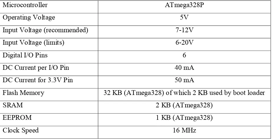
Table 1: Microcontroller ATmega 328P Specification
Microcontroller ATmega328P
Operating Voltage 5V
Input Voltage (recommended) 7-12V
Input Voltage (limits) 6-20V
Digital I/O Pins 6
DC Current per I/O Pin 40 mA
DC Current for 3.3V Pin 50 mA
Flash Memory 32 KB (ATmega328) of which 2 KB used by boot loader
SRAM 2 KB (ATmega328)
EEPROM 1 KB (ATmega328)
8
2.2 Board Arduino Duemilanove
The arduino duemilanove is an open source physical computing platform based on a simple I/O board and development environment that implements the processing/wiring language. Arduino can be used to develop stand alone interactive object or can be connected to software on computer. The benefit of using this arduino is, the user can upload their program direct into microcontroller by using bootloader via USB without external programmer. Besides that, user also has the option either wants to use bootloader or external programmer. The arduino boards can directly using the USB power source as an input voltage. This circuit provides 6 PWM output from digital I/O. If circuit using the bootloader as an uploader to microcontroller, the 2KB out of 32KB flash will be used on bootloader function.
9
2.3 Brushless Outrunner Motor
Brushless motor were used as opposed to brushed motors for the Quadcopter. Brushless motor provide more torque compare to brushed motors, which means the Quadcopter can lift with less work from the motor. Brushless motor do not produce heat at high speed and it is very important because the motor have to spin at very high speed to obtain flight and the brushless cannot overheat. The only problem with brushless motor is, the brushless motor are very expensive. However, the extra torque they provide makes it necessary that we use brushless motor in our design.
All of the motor will run at 11.1v and use 1050KV rating. The KV rating is the number of revolutions per minute that the motor will turn when one volt is applied with no load attach to the motor. Motor with lower KV rating can produce a higher torque, which allows them to drive a bigger propeller. This is important because the bigger the propeller used, it will become more stable on Quadcopter.
The motor is the main part of the Quadcopter. A motor is defined as a device which can convert electrical power into mechanical power. To get the good performance, motor chosen should follow the requirement bellow:
i. Lightweight
ii. High speed and torque iii. Cost effective
10 This project uses four Turnigy 2217, 23A with 1050kv. The reason of using this Outrunner motor because, this Outrunner spinning much slower than Inrunner but it producing more torque. 1050kv is the motor velocity constant by measured in Rpm pre volt.
Figure 2.2: Turnigy Brushless Motor 2217, 23A, 1050kv
Table 2: Turnigy Brushless Motor 2217 Specification
Kv 1050rpm/v
Operating Current 6A ~ 18A
Peak Current 18A
Suggested prop 10x6.0 E-prop
Suggested Battery 1700~2200mAh 3S1P
Weight 71g
Dimensions 27.6 x 36mm
11
2.4 Electronic Speed Control
The Electronic Speed Control is use to vary an electric motor speed and it direction. This Electronic Speed Control commonly used on electrically powered radio controlled. One critical factor to ensure the stable flight is to have the knowledge of the exact rotor RPM, which in turn will mean a better idea of torque. At a constant PWM, the motor will spin at various RPM depending on the dynamic load placed on them. This can create unwanted force which creates more error. One option to ensure motor speed is to place an optical encoder on the motor shaft and combine it with a PID controller to ensure desired RPM.