UNIVERSITI TEKNIKAL MALAYSIA MELAKA
SURFACE INTEGRITY OF AISI 1045 STEEL
WHEN MACHINED WITH CARBIDE-TiC
CUTTING TOOL
Thesis submitted in accordance with the requirements of the University Technical Malaysia Melaka for the Degree of Bachelor of Engineering (Honors) Manufacturing (Process)
By
Mohd Hilmy Bin Mohd Yusof
APPROVAL
This thesis submitted to the senate of UTeM and has been accepted as partial fulfillment of the requirements for the degree of Bachelor of Manufacturing Engineering (Manufacturing Process). The members of the supervisory committee are as follow:
………. Main Supervisor
(Official Stamp & Date)
……… Co-Supervisor
DECLARATION
I hereby, declare this thesis entitled “Surface Integrity of AISI 1045 Steel When Machined With Carbide-TiC Cutting Tool” is the results of my own research except as
cited in the reference.
Signature : ………
Author’s Name : MOHD HILMY BIN MOHD YUSOF
ABSTRACT
DEDICATION
ACKNOWLEDGEMENTS
Alhamdulillah, thank to Allah the Almighty God for giving me strength and patience to work on this Final Year Project Report.
I would like to take this opportunity to express my sincere and deepest gratitude to my Project Supervisor Raja Izamshah b. Raja Abdullah , for his guidance and opinion in the cause of completing this report.
My greatest thanks to my beloved family for their prayers, support and encouragement throughout this entire period of this Final Year Project. I would like to thanks Professor Dr. Mohd. Razali Bin Muhamad, Dean of Faculty of Manufacturing Engineering, University Technical Malaysia, Melaka, Mr. Mohd Hadzley Bin Abu Bakar and to all the lectures in the faculty.
I also would like to convey my biggest thanks to all FKP technicians for supporting me throughout my project. The knowledge and experience I gained from you all will not be forgotten.
I’m also obliged to everyone who had directly and indirectly involve through contributions of ideas, as well as materials and professional opinions.
TABLE OF CONTENTS
Page
Abstract i
Dedication ii
Acknowledgement iii
Table of Contents iv
List of Figures ix
List of Tables xii
Sign and Symbols xii
CHAPTER I INTRODUCTION 1
1.1Objectives 2
1.2Scope of project 3
CHAPTER II LITERATURE REVIEW 4
2.1 Introduction 4
2.2 Common Machine Tools 6
2.3.1 The Basic Parts of Lathe Machine 8
2.3.2 Type Of Lathe 11
2.3.3 Computer Numerical Control (CNC) Lathes 12 2.3.4 Operations Performed In a Center Lathe 13
2.3.4.1 Boring 13
2.4.2 Cutting Geometry 17
2.4.3 Cutting Tool Material 22
2.4.4 Requirements Of Tool Materials 22
2.4.5 Type Tool Materials 23
2.4.5.1 High-speed steel (HSS) 23
2.4.5.2 Cast Cobalt Alloys 24
2.4.5.3 Cemented Carbide 24
2.4.5.4 Diamond 24
2.4.5.5 Ceramics 25
2.4.5.6 Cubic Boron Nitride 25
2.4.6 Coating Materials of Cutting Tools 25
2.4.6.1 Titanium nitride (TiN) 26
2.4.6.2 Aluminum Oxide(Al2O3) 26
2.4.6.3 Titanium aluminum nitride (TiAlN) 26
2.4.7 Tool Coating Processes 27
2.5 Surface Integrity 28
2.5.1 Surface finish 31
2.5.1.1 Surface finish symbols 32
2.5.2 Surface Roughness 34
2.5.2.1 Surface Roughness Measurement 35 2.5.2.2 Surface Roughness Measuring Method 39 2.5.2.3 Surface Roughness Measuring Calculation 44
CHAPTER III METHODOLOGY 46
3.1 Machine Use For Machining 46
3.1.1 Conventional Lathe Machine 46
3.1.2 Computer Numerical Control (CNC) Turning Machine 47
3.2 Selection Of The Work Material 49
3.3 Selection Of Cutting Tool 50
3.4 Centre Drill And Pre -Machining Operation Procedure 51
3.4.1 Centre drill procedure 51
3.4.2 Pre machining operation procedure 53
3.5.1 Cutting speed 54
3.5.2 Cutting time 54
3.5.3 Depth of cut 55
3.5.4 Feed rate 55
3.6 Machining Operation Procedure 55
3.7 NC Code Use In The Machining 58
3.8 Experiment Analysis Method 59
3.8.1 Portable Surface Roughness Tester, SJ-301 59
3.8.1.1 Procedure 60
3.8.2 SEM Operating Parameters 61
3.8.2.1 Sequence To Operation Of The SEM 62 3.8.3 Metallurgy Microscope Operating Parameters 63
3.10 Experiment Procedure Flow Chart 66
CHAPTER IV RESULT 67
4.1 Introduction 67
4.2 Effect of Machining/Cutting Time, T 67
4.3 Tool Wear Effect on Surface 69
4.4 Effect of Cutting Speed on Surface Profile 71
CHAPTER V DISCUSSION 75
5.1 Relationships between the surface roughness and the flank wear 75
5.2 Factors influence the surface integrity 77
5.3 Surface defects on the material after high speed machining 78
5.3.1 None continues waves on surface 78
5.3.2 Plastic deformation 80
5.3.3 Tool deposit 82
CHAPTER VI CONCLUSION 83
6.1 Conclusion 83
6.2 Recommendation 84
LIST OF FIGURES
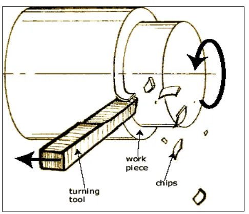
Figure 2.1 Schematic illustration of the basic principle of the turning
operation 8
Figure 2.2 Conventional Lathe Machine Available At UTeM 9
Figure 2.3 Boring Operation 14
Figure 2.4 Facing Operation 14
Figure 2.5 Threading Operation 15
Figure 2.6 Drilling Operation 16
Figure 2.7 Nomenclature of a general-purpose lathe toolbit 18
Figure 2.8 Cutting Tool Geometry 19
Figure 2.9 Coated Cutting Tools 27
Figure 2.10 Surface Integrity Definitions 31
Figure 2.11 Surface Finish Symbols 33
Figure 2.12 Surface Texture Symbols 34
Figure 2.13 (a) Surface Produced (b) Cross Section through Surface
Irregularities 37
Figure 2.14 Basic Characteristics Of Surface Roughness Measurement
(ASME standard B46.1, 1995) 38
Figure 2.15 Effect of Cutting Speed on the Surface Roughness of
Turned Specimens of Mild Stee 38
Model of Surface Roughness
Figure 2.17 Measuring surface roughness with stylus 40
Figure 2.18 Path of stylus in surface roughness measurements (broken
line) compared to actual roughness profile 40
Figure 2.19 Schematic Of Stylus Profile Device For Measuring Surface
Roughness And Surface Profile With Readout Devices 41
Figure 2.20 Microtopographer, a stylus profile device used to measure
and depict surface roughness and character 41 Figure 2.21 Scanning Electron Microscope Machine 42 Figure 2.22 Example of the Surface Integrity Scan Using SEM 43
Figure 2.23 Measuring the Surface Roughness 43
Figure 2.24 Schematic for measuring the surface roughness using stylus
principle 44
Figure 3.1 Conventional lathe machine 47
Figure 3.2 CNC lathe machine 48
Figure 3.3 The Cutting Tools Specifications 50
Figure 3.4 : TiALN Coated Cutting Tool 50
Figure 3.5 Cutting tool and the holder 51
Figure 3.6 Centre drill bit 52
Figure 3.7 Center drill operation 51
Figure 3.8 Material Before Pre-Machining 53
Figure 3.9 Pre machining operation 54
Figure 3.10 Machining operation performing 56
Figure 3.11 Tied the cutting tool at the tool holder 56 Figure 3.12 Work piece clamp at the machine chuck 57
Figure 3.13 The Surf test SJ-301 59
Figure 3.14 The surface roughness tester preparation 60
Figure 3.15 The SEM Machine Used 62
Figure 3.17 Position Of Material On The Microscope Table 64
Figure 3.16 Metallurgy microscope 64
Figure4.1 Surface Roughness vs Cutting Time Graph 69
Figure 4.2 Flank Wears vs Cutting Time Graph 71
Figure 5.1 The Relationships Between Surface Roughness Value And
The Average Flank Wear 76
LIST OF TABLES
Table 2.1 Types of Lathe Machine Available 11
Table 2.2 Defination Of Tool Angles 20
Table 2.3 Recommended tool angles for HSS and carbide 21
Table 2.4 ISO-Recommended Roughness Values and Grade Numbers
for The Specification Of Surface Roughness 37
Table 3.1 Specifications of CNC Lathe Machine 48
Table 3.2 Nominal composition of AISI 1045 Medium Carbon Steels 49
Table 3.3 AISI 1045 Workpiece Properties 49
Table 4.1 Data for Surface Roughness 68
Table 4.2 Data for Average Flank Wear 70
Table 4.3 The Surface Texture Of The Material Using Microscope 72 Table 4.4 The Selected Surface Texture Of The Material Using
LIST OF ABBREVIATIONS, SYMBOLS, SPECIALIZED
NOMENCLATURE
C - Constant, y intercept cutting speed at tool life of 1 minute
D - Diameter
CHAPTER 1
INTRODUCTION
Machines, metalworking and machining process are among the most importance
elements of modern technology. Almost every modern product manufactured worldwide
relies the vast array of disciplines practiced in these three major elements.
Machining is the process of removing the unwanted material from the workpiece
in the form of chip. When the process involved material such as metal, the process is
often called the metal cutting or the metal removal. Material removal process and
machining are indispensable to manufacturing technology. Ever since lathes were
introduced in the 1700’s, many processes have been continuously developed.
Over the past few years in the manufacturing, have seen some progressed in the
cutting tools technology. From the use of high-carbon steel, high-carbon speed steel,
cobalt matrix and solid carbides to cemented or sintered carbides, ceramics and special
cutting tools such as titanium nitride, titanium carbide and many more. All these
developments have given very large advantages where we can see that the new
technologies in cutting tools have been increased the production rates coupled with cost
savings.
Today’s coating technology has contributed significantly to the advancement of
materials for the metal-cutting industries. Various coatings, especially those obtained by
rate, resulting in higher productivity. This has been proven beyond a doubt for the
coated tungsten–carbide tools and since it has been the practice to use coated tools
whenever possible to get the best performance from a cutting tool.
The quality of machined surface is characterized by the accuracy of its
manufacture with respect to the dimensions specified by the designer. Every machining
operation leaves characteristic evidence on the machined surface. This evidence in the
form of finely spaced micro irregularities left by the cutting tool. Each type of cutting
tool leaves its own individual pattern which therefore can be identified. This pattern is
known as surface finish or surface roughness.
A surface is a boundary that separates an object from another object or
substance. Real surface is the actual boundary of an object. It deviates from the nominal
surface as a result of the process that created the surface. The deviation also depends on
the properties, composition, and structure of the material the object is made of.
1.1 Objectives
The objectives of this experiment are:
1. To study the relationship between the surfaces roughness values and turning
parameters such as cutting time during high speed machining. From the study,
we were able to study whether high speed machining would able to produces
better surface finish.
2. To analyzed the surface integrity of the material of high speed machining
1.2 Scope of project
This project is about investigating the surface integrity on AISI 1045 carbon steel
during turning operation using Carbide-TiC cutting tools. This study is done on the CNC
lathe machine in the room temperatures. During this machining several cutting
parameters such as cutting speed remains constant which is 700 rpm and they are
involved such as cutting speed and cutting time.
Surface roughness tester, microscope and Scanning Electron Microscope (SEM)
will be used to measure and identify the surface roughness and the surface integrity. This
will determine the surface integrity of the material after completing the machining
operations. The factors that influence the surface integrity and the surface roughness are
will be identified after the material have been machined.
CHAPTER 2
LITERATURE REVIEW
2.1 INTRODUCTION
Machine tools and cutting tools have advanced in great developments in the past
few years. In the past few years ago, machining is a difficult task to be performed but
now this task has become commonplace and have been simplified with more advanced
technology that have been involved. Machining, the broad term used to describe
removal of material from a workpiece (Kalpakjian, 2001).
With the advancement of technology with the increased of development of higher
grades of steel and other non-ferrous metal and high temperatures refractory materials
and their application, has changed not only the technology of machining but also the
development of cutting tools. In the wide development of the cutting tools, it also affects
the surface of the materials that have been machined.
According to Finnie, who published a historical review of work in metal cutting
(Finnie, 1956), early research in metal cutting started with Cocquilhat in 1851
(Cocquilhat, 1851) and was mainly directed toward the work required to remove a given
volume of material.
In 1881, Mallock (Mallock, 1882) suggested correctly that the cutting process
importance of the effect of friction occurring on the cutting-tool face as the chip
removed.
Today’s coating technology has contributed significantly to the advancement of
materials for the metal-cutting industries. Various coatings, especially those obtained by
using PACVD (plasma assisted chemical vapour deposition) and PVD (physical vapour
deposition), have been found to enhance tool life and increase cutting speed and
feed-rate, resulting in higher productivity (To¨nshoff et al, 1997).
Several studies were carried out in order to determine the relationship between
process parameters and layer properties on the last few years and surface integrity of the
substrate material is important in order to meet the demands of sufficient coating
adhesion (Gebauer et al, 1997). The surface technologies have been increased due to the
development of the cutting tools and machine tools.
Turning is the one of the operation that involved in the material removal or
cutting operation. Turning means that the part is rotating while it is being machined.
(Kalpakjian, 2001). Turning is then divided into two main processes which is roughing
and finishing.
In the roughing operation, the surface of working material usually is roughness
and not smooth surface because roughing is the first operation in turning before perform
the finishing operation. Mean-while in the finishing process, it is a process which it
involved small amount of material removal in one time and main purposed of this
2.2 COMMON MACHINE TOOLS
Machine tools are generally powered-driven metal-cutting or forming machines
used to shape metal by:
I. The removal of chips
II. Pressing, drawing or shearing
III. Controlled electrical machining processes
Any machine tools generally have the capability of:
I. Holding and supporting the workpiece
II. Holding and supporting a cutting tool
III. Imparting suitable movement (rotation or reciprocating) to
the cutting tool or the work
IV. Feeding the cutting tool or the work so that the desired
cutting action and will be achieved
The machine industry is divided into several different categories, such as the general
machine shop, the tool room and the production shop. The machine tools found in the
metal trade fall into three broad categories:
1. Chip-producing machines, which form metal to size and shape by cutting away
the unwanted sections. These machine tools generally alter the shape of the steel
products by casting, forging or rolling in a steel mill.
2. Non-chip-producing machines, which form metal to size and shape by pressing,
drawing, punching or shearing. These machine tools generally alter the shape of
the sheet steel products and also produce parts which need little or no machining
3. New-generation machines, which were developed to perform operations, would
be very difficult, if not impossible to perform on chip- or non-chip producing
machines. Electro-discharge, electro-chemical and laser machines, for example,
use either electrical or chemical energy to form metal to size or shape.
2.3 MACHINING OPERATION– TURNING LATHE
For this project, the main machining operation involved is the turning process.
Turning is the machining operation that produces cylindrical parts. In its basic form, it
can be defined as the machining of an external surface, it is performed on a machine
called a lathe in which the tool is stationary and the part is rotated. The operation
involved the following:
• The workpiece is rotated,
• Using a single-point cutting tool, and
• With the cutting tool feeding parallel to the axis of the workpiece and at a
distance that will remove the outer surface of the work
Turning constitutes the majority of lathe work. The cutting forces resulting from
the feeding the tool from right to left and be directed towards the headstock to force the
workpiece against the workholder. The single-point tool is moved parallel to machine
spindell for straight or contour turning of the outside diameter. From the tools, both flat
and circular, were at one time fed into the workpiece to produce the desired contour of
Figure 2.1: Schematic illustration of the basic principle of the turning operation (Efunda Engineering Fundamental, 2006).
2.3.1 The Basic Parts of Lathe Machine
In the lathe machine it is divided into five main parts. The five main parts of the
lathe are:
I. the bed,
II. the headstock,
III. the carriage,
IV. the tailstock,