THE DEVELOPMENT OF AN ACTIVE GREASE TRAP FOR DOMESTIC APPLICATION
JUFFRIZAL KARJANTO
RESEARCH VOTE NO:
PJP/2012/FKM(19C)/S01114
Fakulti Kejuruteraan Mekanikal
Universiti Teknikal Malaysia Melaka
2014
THE DEVELOPMENT OF AN ACTIVE GREASE TRAP FOR
DOMESTIC APPLICATION
(Keywords: fat, oil and grease, wastewater, passive grease trap, active grease trap)
This research focuses on development of filtration of solid waste and fat, oil and grease (FOG) that mixed in the wastewater coming from the domestic usage, especially the residential kitchen sink, and for food industries. Fat, Oil and Grease (FOG) are the three elements usually found in the municipal sewage systems as the results of improper disposal from the sink, coming from domestic and commercial kitchen. The absent or inefficient of a plumbing device known as grease trap has caused this damage. Grease trap is a structure with special mechanism to trap the FOG in the wastewater. Usually, it is placed under the sink for domestic application while for industrial usage, most of the time it is buried underground to accommodate bigger structure of the grease trap. There are two types of grease trap, one is active grease trap (AGT) and the other is passive grease trap (PGT). The application of PGT is simple and cheap in cost but alas the PGT has a limitation in terms of the maximum capacity and the operational reliability since most often than not, PGT is operating based on the gravitational law. On the other hand, AGT usually has a complex design equipped with temperature-controlled device, hydrostatic pressure or automated tool to enhance the processing rate. In addition, there are two parameters that govern the construction of grease trap which are the retention time and flow rate and also the ratio of sizing including the empirical formulations regarding the flow rate and the retention time will be studied and discussed thoroughly in this research. Furthermore, the understanding of the nature of the FOG, the best structure for the grease trap, the construction and experiments on the prototype, the related calculations, and the design restrictions were covered in this research. Hence, a conceptual AGT design will be developed and later a working prototype will be developed to validate the conceptual design. In addition, the research will also focus on the correlation studies of the parameters that govern the retention time of oil in wastewater and also the grease trap sizing ratios (empirical formulation).
Key Researchers:
Juffrizal Karjanto Nidzamuddin Md Yusof Mastura Mohammad Taha
Mohd Nazmin Maslan
Email: [email protected] Tel. Number: 06-2346855
Project Number: PJP/2012/FKM(19C)/S01114
ACKNOWLEDGEMENTS
Given this opportunity, I would like to express my deepest gratitude to Allah S.W.T for His guidance and blessings that give me strength and wisdom to complete this project.
I would also like to extend my special appreciation to my co-researchers, Nidzamuddin Md Yusof, Mastura Mohammad Taha and Mohd Nazmin Maslan for their tremendous dedications and commitments throughout this project.
A very special thank to my Project Sarjana Muda (PSM) students, Md Shaifuddin Md Salleh and Amar Aizat Rohizan for their continuous commitments and contributions.
Lastly, for my wife, Rafidah and little buddy, Adham, your loves has made this journey a joyous ride.
TABLE OF CONTENTS
ACKNOWLEDGEMENTS ... IV
TABLE OF CONTENTS ... 1
LIST OF FIGURES ... 2
LIST OF TABLES ... 3
LIST OF GRAPHS ... 3
LIST OF ABBREVIATIONS ... 5
CHAPTER 1: INTRODUCTION ... 7
1.1 Problem Statement ... 8
1.2 Objectives ... 9
CHAPTER 2: LITERATURE REVIEW ... 10
2.1 Grease Trap ... 10
2.2 Household Kitchen Sink ... 15
2.3 Prior Arts Search ... 16
CHAPTER 3: METHODOLOGY ... 21
3.1 Conceptualization ... 21
3.1.1 Design Concepts & Selection... 21
3.2 Product Architecture ... 22
3.2.1 Schematic of Product Elements ... 22
3.2.2 Product Cluster ... 24
3.2.4 Fundamental and Incidental Interactions ... 26
3.3 Prototype Experimentation ... 28
CHAPTER 4: RESULTS AND DISCUSSIONS ... 34
4.1 Calculation and Theoretical ... 34
4.1.1 Flow rate Calculation ... 34
4.2 Construction of Grease Trap ... 36
4.2.1 Empirical Formulation for Sizing the Grease Trap ... 39
4.3 Prototype Analysis ... 41
4.4 Passive Grease Trap Sizing Guideline ... 45
CHAPTER 5: CONCLUSION AND FURTHER WORKS ... 47
REFERENCES ... V APPENDICES ... VIII LIST OF FIGURES Figure 1: Example of Existing Grease Trap (Source: Lakasa, 2006) ... 10
Figure 2: Blockages in Drain Pipe (Source: MMS, 2004) ... 11
Figure 3: Types of Grease Trap (Source: MMS,2004) ... 11
Figure 4: Example of overfill grease trap (Source: Lakasa, 2006). ... 13
Figure 5: Grease Trap (Source: US 5,993,646, 1999)... 18
Figure 6: Passive Grease Trap Using Separator Technology (Source: US 7540967 B2, 2007)) ... 19
Figure 7: Passive Grease Trap with Pre-Stage for Solids Separation (Source: US
2009 0107910, 2009) ... 20
Figure 8: Schematic of Product Element ... 23
Figure 9: Product Cluster ... 25
Figure 10: Product Geometry ... 26
Figure 11: Fundamental and Incidental Interactions ... 27
Figure 12: Half-Scale Prototype... 28
Figure 13: Experimental Set Up ... 29
Figure 14: The Movement of the Oil Particles without any Emulsifier ... 30
Figure 15: The Captured Oil and Collected Wastewater without Soap ... 31
Figure 16: Layer of Oil on top of the Wastewater ... 31
Figure 17: The Imitation of Wastewater plus Emulsifier (Washing Powder) ... 31
Figure 18: The Dispersion of Wastewater with Emulsifier ... 32
Figure 19: Wastewater with Emulsifier Effects ... 32
Figure 20: The Region of Volume of the Wastewater ... 42
Figure 21: Region under the Sink (Conventional Non-Renovated Sink) ... 44
Figure 22: Grease Trap’s (shown in dashed line) Location inside the Region under the Sink (shown in solid line)... 45
Figure 23: Passive Grease Trap Sizing Guideline... 46
Figure 24: Improper FOG Dumping and Spillage (Source: MMS, 2004) ... 49
LIST OF TABLES Table 1: Standard Sink Size for Kitchens ... 16
Table 2: Experiment Data Collection ... 29
Table 3: Total and Percentage of Oil and Water Collected ... 30
Table 4: Volumes of Three Types of Sink ... 34
Table 5: The Actual Drainage Loads ... 35
Table 6: 1 and 2 minutes drainage period ... 35
Table 7: Retention Time for Three Sinks without Emulsifier... 38
Table 8: Retention Time for Three Sinks with Emulsifier ... 38
LIST OF GRAPHS Graph 1: Flow Rate for Sink A, B and C at Drainage Times (1 and 2 minutes) ... 36
Graph 2: Flow Rate (GPM) versus Volume of Grease Trap (Cubic Inches) ... 40
Graph 3: The Region of Allowable Volume for Grease Trap ... 43
LIST OF ABBREVIATIONS
FOG Fat, Oil and Grease
PGT Passive Grease Trap
AGT Active Grease Trap
BOD Biochemical Oxygen Demands
COD Chemical Oxygen Demands
FR Flow Rate
RT Retention Time
FAS Ferrous Aluminium Sulphate
MyIPO Malaysian Intellectual Property Office
USPTO United States Patent and Trademark Office
EPO European Patent Office
QFD Quality Function Deployment
FCA Functional Cost Analysis
FMECA Failure Modes Effects and Critical Analysis
CAD Computer Aided Design
BOM Bill of Material
AISI American Iron and Steel Institute
CHAPTER 1: INTRODUCTION
Every day, tons of waste were been produced by residential kitchens, stalls and restaurants. On the same hand, usually, solid waste can be collected and managed into trash bins which later would be dumped properly and accordingly at the authorized dumping site. On the other hand, the liquid waste is harder to retained and disposed. More often than not, these types of waste are being discarded into the municipal sewage line and end up polluting the underground soil and water. In addition, this liquid waste which usually contaminated with “yellow grease” comprises of fat, oil and grease (FOG) in which worsen the situation by floating on top of the wastewater (Services, 2004). Hence, not allowing the oxygen to neither get into or out from the wastewater. Besides that, there are also fine solid wastes, lubricant and emulsifier agent like soap that only lengthen the retention time for oil-based waste and contaminated the water by forming a layer which stop the oxygenation of the wastewater. An accumulated FOG inside the pipeline or sewage system would congeal over the time which could cause the blockage in the system and the waste would back-up into the sink or manhole (Services, 2004).
Grease trap is a structure with special mechanism to trap the FOG in the wastewater. Usually, it is placed under the sink for domestic application while for industry usage, most of the time it is buried underground to accommodate bigger structure of the grease trap. When the food waste and wastewater are poured into the sink, the grease will accumulate at the p-trap or s-trap and later would clog the disposal system. In addition, a clogged sink and sewage system will cause foul smell and pollute the environment from underneath. Proper disposal of grease is an important waste-management concern. Since all of the type of greases is lighter than
water, it tends to spread into thin and wide membranes which obstruct the oxygenation of water. Because of this, a single litre of grease waste can contaminate as much as 1 million litres of water. Thus, wastewater from kitchen sink needs a proper way of filtration and disposal. In addition, the collective grease can be recycled and used to produce an energy source, biodiesel.
Biodiesel has the potential to substitute mineral oil in various industrial applications as in fuel and energy management. The nontoxic and biodegradable characteristic of oil-based grease will cause less danger to environment in case of accidental spillage or during disposal of the material. While transforming from waste into wealth, it will cost lesser expenditure if compared to the mineral oil. Several companies in Malaysia already provide services to collect all the waste grease from household, such as Fathopes Energy Sdn. Bhd (Home: Fathopes Energy), which collects used cooking oil at totally no cost and provide reliable and efficient pick up service.
1.1 Problem Statement
Grease trap has been a compulsory device and need to be installed for industries application before releasing waste water into the municipal sewage system. On the other hand, for domestic usage, it has been promoted that grease trap need to be installed in every house but such laws have not been enforced yet in Malaysia. On the same hand, the awareness of this matter cannot be taken lightly as other effects such as stinky and smelly clogged sink and drains, polluting the sewage system and the possibility of law enforcement on maximum biochemical oxygen demands (BOD) for household waste water before it can leave the house sewage system.
There are only a few types of grease trap found in Malaysia and more in international market especially in the United States of America. Most of these inventions are expensive and high in maintenance in term of the disposal of the trapped grease. Usually, a grease trap would need to be serviced at certain period of time to remove the trapped grease from the grease trap’s system. Sometimes, it will get really dirty as the grease trap’s cover need to be opened and the trapping operation need to be stopped. Meanwhile, some grease traps are bulky and hard to install especially in limited space under the sink. Alas, some low-cost residential like flat apartments have a very small kitchen area and space is really a nemesis which needs to be tackled down. Another problem is the material for the grease trap. Depending on the design of the grease trap, the materials need to have a high resistance towards corrosion and also easy to be fabricated. Plus, the design will be in advantage if it is simple in construction and easy in operation.
1.2 Objectives
The general objectives for this project are to study and understand in-depth the nature of FOG, the best structure for grease trap and the design restrictions. The specific objectives of this project are:
i. To investigate the conceptual design of a passive grease trap. ii. To validate the conceptual design by developing a prototype.
iii. To correlate the parameters that governs the retention time of oil in wastewater and also the grease trap sizing ratios.
CHAPTER 2: LITERATURE REVIEW
2.1 Grease Trap
Grease trap as shown in Figure 1 which have been used since Victorian era (1837), is plumbing mechanism proposed to trap FOG before they enter a wastewater disposal system. FOG can be in three different forms; solids (fats), liquids (oils) and liquid-solid (grease) at normal room temperature.
Figure 1: Example of Existing Grease Trap (Source: Lakasa, 2006)
General wastewater usually contains small amounts of oils which enter into septic tank or treatment facility to form a floating scum layer. This scum layer is very slowly digested and broken down by microorganisms in the anaerobic digestion process. However, very large amounts of oils from food waste in kitchens or restaurants can overwhelm the septic tank or treatment facility, resulted in problem of untreated sewage. Furthermore, high viscosity fats solidify when cooled, and can combine with other disposed solids to form blockages in drain pipes as shown in Figure 2.
Figure 2: Blockages in Drain Pipe (Source: MMS, 2004)
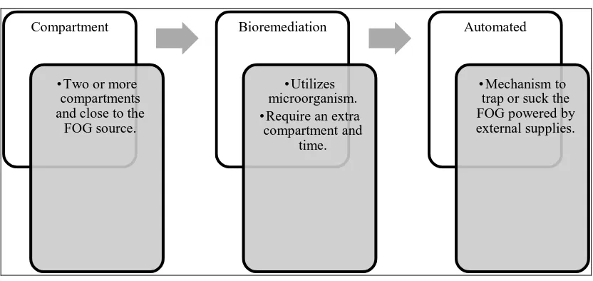
Types of Grease Trap
Figure 3: Types of Grease Trap (Source: MMS,2004)
In general, there are three types of grease trap as shown in Figure 3. In addition, the first type is also known as Passive Grease Trap (PGT) and the second and third one is also known as Active Grease Trap (AGT). The first one is compartment grease trap or known as ‘Weir Type’ is a kind of grease trap which usually placed close to the FOG source (Middleton & Starr, Sept.1995). In addition, it has a compartment where the trapped grease is held and after a certain time, the compartment needs to be removed or cleaned in order to expel the trapped grease.
This type of grease trap restricts flow and removes 85-95% of the incoming FOG and the sizing is based on the size of the compartment sink, dishwasher, pot sinks and mop sinks. This kind of grease trap is also known as (PGT) or Passive Grease Trap since there it is operated by the gravitational law (Batten & Kyles, June.2009).
The second types is known as bioremediation grease trap. This type of grease trap utilizes microorganism to digest the trapped grease, converting it to water soluble, bio-degradable fluid which are safely discharged into the drainage system. This type of grease trap accompanied with bio reactor which filled with immobilized enzyme such as candida rugosa and pseudomonas cepacia (Oya, March.2007), (Ozama, March.1999). On the same hand, bioremediation grease trap require an extra compartment and time (2-5 hours) for the digesting process to happen or known as ‘residence time’.
The third type is the automated version of grease trap. Typically, automated grease trap has hydrostatic pressure, skimmer device or automatic draw-off system to remove or suck the FOG. In some, there are also a temperature-controlled grease trap in which the trapped grease is heated and turned into liquid grease that later been pumped out into a separate tank (Holloway Jr., Held, Roach, & Mielbeck, June.1995). This type of grease trap usually smaller than others because it does not need a bigger compartment since the grease trap coming in is usually being processed at upon arrival.
Principe of Function
Main functions of a grease trap are to trap the FOG from waste water and collect the FOG and channel it into a designated location. All type of grease trap is usually applying the same physics which is that grease and oil are lighter than water and will rise to the top when the mix wastewater is allowed to reside for some times. However, grease trap which designed to hold the grease within its separation chamber or compartment was constantly reducing its working volume and hence its ability to allow separation required what is known as Retention Time (RT). When the grease trap is constantly used and filled with waste water, sometimes, the RT is exceeded and overfill could easily occur as shown in Figure 4.
Figure 4: Example of overfill grease trap (Source: Lakasa, 2006).
escape into the drainage sewer system and as well creates smelly surrounding in the kitchen area. A better grease trap need some sorts of food waste trap like perforated basket to avoid this problem, but it still need to be cleaned up regularly, depending on the food consumed by the households or customers.
Another problem of typical grease trap is that the FOG must be emptied either by scooping out or pumping all the FOG. Grease trap with separated chamber for FOG that is easily detachable is preferred in new design of grease trap. The user is also need to deliver the FOG to a specialist renderer or to recycle agent. Consequently, this is a very unpleasant job and in consequence, always neglected, causing the same problems as if the grease trap were not there at all because the user might dispose it back down to the drain and into the municipal sewage lines.
The usage of chemicals such as emulsifying agents (not as bioremediation grease trap type) and hot water to liquefy the solid FOG would only push the grease further into the drainage sewer system. The FOG problem is fixed temporarily because the blockages in the drainage would still occur in the latter phase of the sewage system. It is because the liquefied FOG would be re-hardened when it is back to its normal temperature and clog the drainage pipe again.
Some manufacturers, especially from United Kingdom (UK) and United States of America (USA), recommend the combination approach of grease trap where it would physically stop or trap FOG mechanically and dosing it by adding biological agents (like bioremediation grease trap type) into the grease trap (Grease Management Explained, 2010). This method can be very efficient as well as very simple to maintain as well as effective in cost. But the dosing system must be heavily
monitored in order to achieve high efficiency. In addition, it is difficult to find such grease trap chemicals, bacteria or enzymes that had certified testing to prove the quality (Oya, March.2007). Improper use of these biological agents can cause an extreme cost to repair the plumbing system and also the treatment facilities where it is contaminated due to high level of toxicity.
In general, a good grease trap should have the following criteria:
i. Means of preventing the food waste from entering the tank. ii. Steady inviscid flow rate to give time for the grease to cool and
separate from the waste water (retention time).
iii. A reliable means of separating grease from water preferably a passive type of grease trap.
iv. Simple steps and low frequency in maintenance.
v. Means of cleaning the grease trap including disposal of concentrate sludge the bottom of the tank such as flush valve.
vi. High durability and resistance material (no rust or leakage).
2.2 Household Kitchen Sink
A sink (also hand basin and washbasin) is a bowl-shaped plumbing fixture used for washing hands, dishwashing or other purposes. Sinks generally have taps (faucets) that supply hot and cold water and may include a spray feature to be used for faster rinsing. They also include a drain outlet to remove used water. This drain may itself include a strainer and/or shut-off device and an overflow-prevention device. In addition, they may also have an integrated soap dispenser.
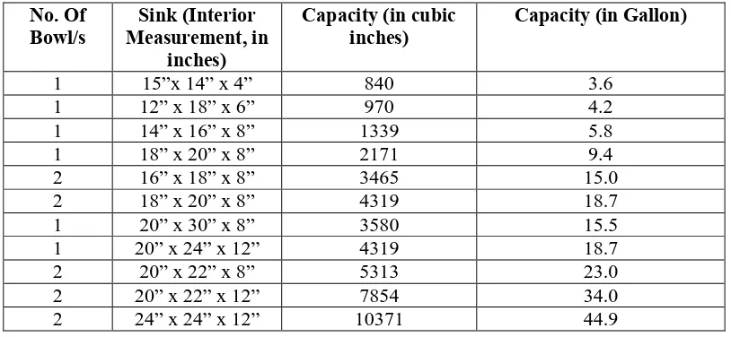
Nowadays there are many shape and size of the kitchen sink but mostly they used standard size sink for maintenance and ease of spare parts finding. Table 1 shows the standards sink size (Lakasa Installation, 2006).
No. Of
Bowl/s Measurement, in Sink (Interior inches)
Capacity (in cubic
inches) Capacity (in Gallon)
1 15”x 14” x 4” 840 3.6
Table 1: Standard Sink Size for Kitchens
2.3 Prior Arts Search
Patent 1: Food Waste, Oil and Grease Interceptor
• Inventor: Ku Halim Bin Ku Hamid and Melati Binti Kassim
• Date of Patent: 31 March 2011
• Patent No: MY-143226-A (MyIPO).
In this invention, Ku Halim and Melati invented a grease trap which is installed under the sink. The grease trap function is to treat dish water which contains solid food waste, grease and oil before discharging it into sewage system. The product includes a container, an inlet, a filter and a water outlet connecting to a second discharging outlet. A grease and oil outlet is connected to a second
discharging outlet and the outlet valve is places at the bottom of the container. The waste water will run through the container and then filter before exiting the discharging outlet.
Patent 2: Waste Separator System
• Inventor: Aliza Binti Bedol and Shaharudin Bin Ismail
• Date of Patent: 13 February 2003.
• Patent No: MY-130317-A (MyIPO).
Waste separator system is a fine invention from Aliza and Shaharudin and this grease trap’s patent has been granted and published to public. All the process are happen in vertical position as it started by filtering the solid waste in the filtering bag and then the accumulated grease will be trapped and discharged through the outlet into a container and is controlled by a valve. There is also a cap on top of the grease trap to supply ventilations and air pressure to smoothen the waste water flow. In order to dispose the trapped grease, the cover need to be opened and the filtering bag need to be removed and cleaned.
Meanwhile, searching in USPO unravels a lot of type of grease traps. In addition, they supply full documents of the patents including data, analysis, drawings and details. In this project, three prominent patents from USPO are presented as many others were studied and will be mentioned in the later part of this thesis.
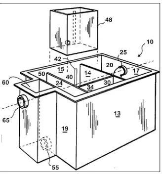
Patent 3: Grease Trap
• Inventor: James S. Powers
• Date of Patent: 30 November 1999
• Patent No: US 5,993,646 (USPO)
This grease trap is a great invention from James S. Powers from the United States of America. Different from most of others, his invention needs to be installed in horizontal position. Figure 5shows that there are five compartments altogether in this grease trap, the inlet chamber, the preliminary chamber, the outlet chamber, the discharge chamber and reservoir chamber, respectively, from the left to the right side. The flow of waste water will have to travel through these chambers accordingly and there are orifices between each of the two chambers. The grease will be trapped and kept in the reservoir chamber and there is a gauge at the outside of the grease trap to indicate the level of waste accumulated. One of the advantages of this grease trap is that there is reservoir chamber that is detachable for easy cleaning and disposal of the build-up trapped grease. But this system also shows that the compartment for the food waste is submerging in water.
Figure 5: Grease Trap (Source: US 5,993,646, 1999)
Patent 4: Passive Grease Trap Using Separator Technology
• Inventor: William C. Batten and Bruce W. Kyles
• Date of Patent: 8 November 2007
• Patent No: US 7540967 B2 (USPO)
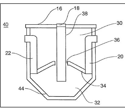
Figure 6: Passive Grease Trap Using Separator Technology (Source: US 7540967 B2, 2007))
The invention of this grease trap is that it has a tank having a downwardly shaped bottom (Figure 6). An upwardly shaped divider in middle divides the tank into upper and lower chambers. A hole near an upper part of the divider allows grease into the upper chamber. The tank has inflow and outflow for wastewater at the side of the system. A pipe extends through the hole in the divider into the lower chamber for removing solid waste. Residue and grease from both chamber (upper and lower) is removed by applying suction to the pipe to suck all of the flowable contents out of system. This system has its own disadvantage because to clean the system, another system need to be used (suction), where it will be costly and user cannot see the cleanliness inside lower chamber since it is close chamber. Another disadvantage is the chamber is made from roto-molded plastic, where it cannot last long due to chemical corrosion from grease and other residue.
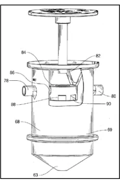
Patent 5: Passive Grease Trap with Pre-Stage For Solids Separation
• Inventor: William C. Batten and Bruce W. Kyles
• Date of Patent: 30 April 2009
• Patent No: US 2009 0107910 (EPO)
Figure 7: Passive Grease Trap with Pre-Stage for Solids Separation (Source: US 2009 0107910, 2009)
This invention is almost the same from the previous mentioned patent because it had been designed by the same inventors. They improved their design by adding the upwardly shaped divider with solid diverters (shown in Figure 7) and added another chamber in the lower part of the chamber as solids collector. The diverters make sure that the solids stay at the sidewall of the chamber. The solids collector includes a roto-molded plastic container having a cylindrical sidewall and a downwardly sloping bottom, which help the solids flow into the bottom of the chamber, and it can be detached from the whole system for maintenance. But the disadvantage of the system is the same as mentioned before, because in order to remove the grease from the chamber, the suction mechanism is still need to be applied to the system.