UNIVERSITI TEKNIKAL MALAYSIA MELAKA
THE EFFECT OF AXIAL CRACK LENGTH ON THE PLASTIC
BUCKLING OF RELATIVELY THICK CYLINDER SUBJECTED
TO AXIAL COMPRESSION
This report submitted in accordance with requirement of the Universiti Teknikal Malaysia Melaka (UTeM) for the Bachelor Degree of Engineering Technology
(Automotive Technology) (Hons.)
by
MOHD HAZRIN B MOHD IBRAHIM KHAN B071210195
930522-05-5115
UNIVERSITI TEKNIKAL MALAYSIA MELAKA
BORANG PENGESAHAN STATUS LAPORAN PROJEK SARJANA MUDA
TAJUK: THE EFFECT OF AXIAL CRACK LENGTH ON THE PLASTIC BUCKLING
OF RELATIVELY THICK CYLINDER SUBJECTED TO AXIAL COMPRESSION
SESI PENGAJIAN: 2015/16 Semester 1
Saya, Mohd Hazrin Bin Mohd Ibrahim Khan
mengaku membenarkan Laporan PSM ini disimpan di Perpustakaan Universiti Teknikal Malaysia Melaka (UTeM) dengan syarat-syarat kegunaan seperti berikut:
1. Laporan PSM adalah hak milik Universiti Teknikal Malaysia Melaka dan penulis. 2. Perpustakaan Universiti Teknikal Malaysia Melaka dibenarkan membuat salinan
untuk tujuan pengajian sahaja dengan izin penulis.
3. Perpustakaan dibenarkan membuat salinan laporan PSM ini sebagai bahan pertukaran antara institusi pengajian tinggi.
4. **Sila tandakan ( )
SULIT
TERHAD
TIDAK TERHAD
(Mengandungi maklumat yang berdarjah keselamatan atau kepentingan Malaysia sebagaimana yang termaktub dalam AKTA RAHSIA RASMI 1972)
(Mengandungi maklumat TERHAD yang telah ditentukan oleh organisasi/badan di mana penyelidikan dijalankan)
(TANDATANGAN PENULIS)
FAKULTI TEKNOLOGI KEJURUTERAAN
PENGKELASAN LAPORAN PSM SEBAGAI SULIT/TERHAD LAPORAN PROJEK SARJANA MUDA TEKNOLOGI KEJURUTERAAN PEMBUATAN (COURSE NAME): AAA BIN BBB
Sukacita dimaklumkan bahawa Laporan PSM yang tersebut di atas bertajuk
“Quality and Performance Investigation of TiAlN Coated Drill Tools”
mohon dikelaskan sebagai *SULIT / TERHAD untuk tempoh LIMA (5) tahun dari tarikh surat ini.
2. Hal ini adalah kerana IANYA MERUPAKAN PROJEK YANG DITAJA
OLEH SYARIKAT LUAR DAN HASIL KAJIANNYA ADALAH SULIT.
Sekian dimaklumkan. Terima kasih.
Yang benar,
________________
Tandatangan dan Cop Penyelia
* Potong yang tidak berkenaan
NOTA: BORANG INI HANYA DIISI JIKA DIKLASIFIKASIKAN SEBAGAI
SULIT DAN TERHAD. JIKA LAPORAN DIKELASKAN SEBAGAI TIDAK
iv
DECLARATION
I hereby, declared this report entitled “The Effect Of Axial Crack Length On The Plastic Buckling Of Relatively Thick Cylinder Subjected To Axial Compression” is
the results of my own research except as cited in references.
Signature :………
Name : ………
v
APPROVAL
This report is submitted to the Faculty of Engineering Technology of UTeM as a partial fulfillment of the requirements for the degree of Bachelor of Engineering Technology (Automotive Technology) (Hons.). The member of the supervisory is as follow:
vi
ABSTRACT
vii
ABSTRAK
viii
DEDICATIONS
ix
ACKNOWLEDGMENTS
x
TABLE OF CONTENTS
DECLARATION ... iv
APPROVAL ... v
ABSTRACT ... vi
ABSTRAK ... vii
DEDICATIONS ... viii
ACKNOWLEDGMENTS ... ix
TABLE OF CONTENTS ... x
LIST OF FIGURES ... xiii
LIST OF TABLE ... xvi
LIST OF SYMBOLS AND ABBREVIATIONS ... xvii
CHAPTER 1 ... 1
1.0 Background ... 1
1.1 Problem Statement ... 2
1.2 Objective ... 3
1.3 Scope ... 3
CHAPTER 2 ... 4
2.0 Introduction of buckling of relatively thick of cylindrical structure ... 4
2.1 Cracks on Cylinder Structure ... 5
2.2 Geometrical structure of cylindrical shell. ... 6
xi
2.5 Analysis Method ... 14
2.5.1 Geometry and Mechanical properties of the shells. ... 15
CHAPTER 3 ... 17
3.0 Research Design ... 17
3.1 Conceptual Design ... 18
3.1.1 Material Selection ... 19
3.2 Welding process of hollow cylinder Welding process of hollow cylinder ... 20
3.3 Grid line process on mild steel cylinders for pre-test measurement process ... 22
3.3.1 Measurement of the specimen ... 22
3.4 Axial compression test ... 24
3.5 Virtual Models (Hypermesh) ... 26
3.6 ABAQUS Analysis ... 29
CHAPTER 4 ... 32
4.0 Cylinder Measurement ... 32
4.1 Numerical Simulation ... 38
4.1.1 Nominal Midsurface and Nominal Thickness... 38
4.1.2 Measured Midsurface and Overall Average Thickness. ... 39
4.2 Experimental models ... 40
4.3 Overall Results based on Simulation ... 42
4.3.1 Experimental Results ... 43
4.3.2 Measured Midsurface + Overall Average Thickness Result... 47
xii
4.4.1 Results after compression of Real Specimen and Analysis ... 51
4.4.2 Results of Experiment and Analysis in the same graph ... 54
CHAPTER 5 ... 55
5.0 Summary of Research ... 55
5.1 Problems Faced During Research ... 56
5.2 Suggestion for Future Work ... 56
APPENDIX A ... 58
APPENDIX B ... 67
APPENDIX C ... 69
APPENDIX D ... 71
xiii
Figure 2.1: Crack edge opening displacement for a given crack length and applied
load (Daunys and Tarakecius, 2006). ... 5
Figure 2.2: Geometry of Undeformed Shell (Brian, 1998) ... 6
Figure 2.3: Buckling behavior as a function of buckling stress (Budiansky et.al, 1966) ... 7
Figure 2.4: The effect of a change in mean imperfection upon the failure probability of symmetric systems with normally distributed imperfections (Roorda, 1968) ... 11
Figure 2.5: The effect of an axisymmetrical dimple imperfection on the buckling of clamped cylindrical shells (constant thickness) under axial compression. (Hutchinson, 1967) ... 11
Figure 2.6: Computation model of cylindrical shells with a circumferential crack (Vaziri et. al, 2006) ... 12
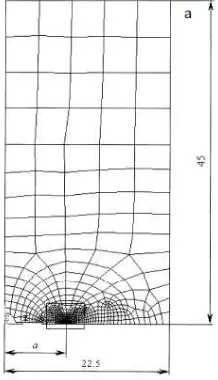
Figure 2.7: Cylindrical Shell constructed using ABAQUS and Numerical Test ... 14
Figure 2.8: Finite Element model details ... 15
Figure 3.1: Project work flow chart ... 17
Figure 3.2: Design of cylindrical shell structure ... 18
Figure 3.3: Percentage of axial crack length to the cylinder axial length (2a/L) ... 21
Figure 3.4: Specimen models welded using MIG welding pro ... 21
Figure 3.5: Grid line drawn on mild steel cylinder ... 22
Figure 3.6: Shows the measurement of cylinder diameter ... 23
Figure 3.7: Shows the measurement of cylinder height ... 23
Figure 3.8: Shows the ultrasonic machine to measure cylinder thickness ... 23
Figure 3.9: Shows the measurement of crack width using filler gauge ... 24
Figure 3.10: Shows the measurement of crack height using vernier caliper ... 24
Figure 3.11: Axial compression test on cylindrical structural model using Instron machine ... 25
Figure 3.12: Main Body of specimen ... 26
Figure 3.13: Plot of nodes ... 27
Figure 3.14: lines between two nodes ... 27
Figure 3.15: Vertical nodes ... 27
Figure 3.16: Surface of crack ... 28
Figure 3.17: Model with no crack created ... 28
Figure 3.18: Formation of crack on models ... 29
Figure 3.19: Load on Top surface ... 30
Figure 3.20: Boundary Condition applied on the models ... 31
xiv
Figure 4.1: Top Outer Diameter ... 33
Figure 4.2: Bottom Outer Diameter ... 33
Figure 4.3: Top Inner Diameter ... 34
Figure 4.4: Bottom Inner Diameter ... 35
Figure 4.5: Height of Model... 36
Figure 4.6: Cylinder thickness ... 37
Figure 4.7: Cylinder free movement ... 40
Figure 4.8: Plot of Compressive Load against Compressive extension based on Experimental result of Model 1 ... 43
Figure 4.9: Plot of Compressive Load against Compressive extension based on Experimental result of Model 2 ... 43
Figure 4.10: Plot of Compressive Load against Compressive extension based on Experimental result of Model 3 ... 44
Figure 4.11: Plot of Compressive Load against Compressive extension based on Experimental result of Model 4 ... 44
Figure 4.12: Plot of Compressive Load against Compressive extension based on Experimental result of Model 5 ... 45
Figure 4.13: Plot of Compressive Load against Compressive extension based on Experimental result of Model 6 ... 45
Figure 4.14: Plot of Compressive Load against Compressive extension based on Experimental result of Model 7 ... 46
Figure 4.15: Plot of Compressive Load against Compressive extension based on Experimental result of Model 8 ... 46
Figure 4.16: Plot of Compressive Load against Compressive extension based on Analysis result of Model 1... 47
Figure 4.17: Plot of Compressive Load against Compressive extension based on Analysis result of Model 3... 47
Figure 4.18: Plot of Compressive Load against Compressive extension based on Analysis result of Model 4... 48
Figure 4.19: Plot of Compressive Load against Compressive extension based on Analysis result of Model 5... 48
Figure 4.20: Plot of Compressive Load against Compressive extension based on Analysis result of Model 6... 49
Figure 4.21: Plot of Compressive Load against Compressive extension based on Analysis result of Model 7... 49
xv
Figure 4.23: Model 1 (H1) ... 51
Figure 4.24: Model 3 (H3) ... 51
Figure 4.25: Model 4 (H4) ... 52
Figure 4.26: Model 5 (H5) ... 52
Figure 4.27: Model 6 (H6) ... 52
Figure 4.28: Model 7 (H7) ... 53
Figure 4.29: Model 8 (H8) ... 53
Figure 4.30: Complete experimental Graph ... 54
xvi
LIST OF TABLE
Table 2.1: Buckling analysis based on different researcher ... 8
Table 3.1: Advantages of mild steel grade A36 in engineering applications... 25
Table 3.2: Properties of mild steel grade A36... 20
Table 4.1: Top Outer Diameter for Model 1 to Model 8 ... 32
Table 4.2: Bottom Outer Diameter for Model 1 to Model 8 ... 33
Table 4.3: Top Inner Diameter for Model 1 to Model 8 ... 34
Table 4.4: Bottom Inner Diameter for Model 1 to Model 8 ... 35
Table 4.5: Height of Model 1 to Model 8 ... 36
Table 4.6: Thickness of Model 1 to Model 8 ... 37
Table 4.7: Maximum load on models (Nominal Midsurface and Nominal Thickness)... 38
Table 4.8: Loads on measured models ... 39
Table 4.9: Load on experimental models ... 41
xvii
c = Stress
y = Yield stress
E = Young Modulus
Al = Aluminium
Cu = Copper
Mg = Magnesium
= Angle of degree
L = length
mm = Millimetre
1
CHAPTER 1
INTRODUCTION
1.0 Background
2
buckling of relatively thick cylinder subjected to axial compression. The materials of cylinder are assumed to be made from mild steel.
1.1 Problem Statement
Defects can have a significant influence on the buckling behavior of thin-walled structures. From the structural point of view, the most detrimental consequences of a defect is the excessive stress, which could result in fracture at or near the defect location and possibly overall structural failure (Babak and Vaziri, 2012). Thus, the manufacturing of the cylindrical structure to be handled carefully to ensure there will be no formation of other defects.
3
Based on some literature review, it is observed that researchers does emphasize on circumferential crack cylindrical structure and multiple longitudinal crack (Allahbakhsh and Shariati, 2014; Babak and Vaziri, 2012; Starnes and Rose, 1997). This research focus on effect of axial crack length on the plastic bucking of relatively thick cylinder subjected to axial compression by experimental action.
1.2 Objective
This study will highlights on the following objectives:
1. To manufacture cylinder with axial crack of different length introduced.
2. To investigate the effect of axial crack length on the plastic bucking of relatively thick cylinder subjected to axial compression.
1.3 Scope
4
CHAPTER 2
LITERATURE REVIEW
2.0 Introduction of buckling of relatively thick of cylindrical structure
5 2.1 Cracks on Cylinder Structure
Destruction of material or structural commonly known due to buckling failure when the thickness of a cylinder is small compared to other cylinders, under membrane loading. Though the cylindrical shell under tension loading, the buckling development may occur under particular state where there is presence of cracks at any angle. Presence of defects, such as cracks, may seriously compromise their buckling behavior and endanger the structural integrity (Dadrasi, 2013). Crack could be the spark for the relatively thick cylindrical structure failure in maintaining the strength of the wall. Two types of damage are well-known; the first one is the formation of macro cracks in the most loaded zones and the second is the growth of macro cracks (Daunys and Tarakecius, 2006). Figure 2.1 shows the finite element model used to calculate the crack edge opening displacement for a given crack length and applied load. Manipulation on the crack line reflects on the results of the structure of element. In the recent years, many studies on fatigue crack and other problems has been performed to investigate the point of failure in the structures.
6
Geometrical structure is an important factor to be analyzed as it explains the details of structure surface. According to (George, 1986) imperfections include a local bubble in a thin circular cylindrical shell, which makes the geometry locally non-symmetric; a global out of-roundness, makes the geometry globally non circularly cylindrical. Accurately, geometry of cylindrical structure could impact the roundness of the shell which manipulates the outcomes after compression. According to (Brian, 1998), the shell can be constructed of any combination of isotropic or orthotropic materials, including either longitudinal or circumferential stiffeners, and it is required to have “material symmetry” about two vertical planes: X = L/2 and Y = 0 as shown in Figure 2.2.
Figure 2.2: Geometry of Undeformed Shell (Brian, 1998)
7
2.3 Buckling behavior of cylinder under axial compression
Buckling is important phenomena to be understood especially for manufacturing process in engineering industry. Cylindrical hollow steel tubes are generally used as segments as a part of numerous auxiliary frameworks. Typical technique of such cylinders when subjected to central pressure and twisting is region clasping almost to the segment end. For instance, hollow steel cylinders are regularly utilized as scaffolding and such span docks endured broad harm and even falls. Throughout the usage, thin-walled cylinders are often subjected to single and combined application of external loads. In resisting these loads, the system is subject to buckling, a physically observed failure mode, which is closely associated with the establishment of its load-carrying capacity (George, 1986).
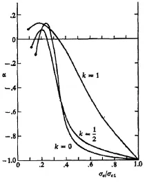
Buckling proceeds in manner which may be either stable or increases displacement in a controlled way as loads are increased, i.e. the structure ability to sustain loads is maintained (Naidu et. al, 2014). The load carrying capacity of thin shells alongside learning of its postbuckling behaviour has been the subject of many researchers through both theory and experiment. According to (Ismail et. al, 2015) too thin cylindrical shells and larger design loads may make the structures more prone to buckling failure. It can be concluded that many factors influences the buckling behavior and different factors provides different results based on the number of load, type of manufacturing and presence of cracks. Figure 2.3 shows the measure of post buckling stability is plotted directly as a function of σc/σcl for each of
the three important cases (Budiansky and Hutchinson, 1966).