DOI: 10.12928/TELKOMNIKA.v14i2A. 4376 403
Image Recognition and Tracking Algorithm Based on
PID Fuzzy Control
Zhan Qu*1, Ru-quan Wen2, Xin-you Wang3, Bei-bei Zhou4 1
College of Information Engineering, Tarim University, Alar,China 2
Mechanical and Electronic Engineering Department, Pingxiang University,Pingxiang, China 3
Gansu Radio & TV University, Lanzhou, China 4
Gansu Agricultural University, Lanzhou, China
*Corresponding author, email: [email protected]
Abstract
Video surveillance systems with image recognition and image tracking capabilities have a wide range of applications in the field of city protection, social security and public safety. In this paper, based on the analysis of image detection and tracking principles proposed image recognition based PID fuzzy control and tracking algorithm. First, the image on the basis of the gray-scale image acquired by the video processor, the binary processing, and then through the expansion operation of mathematical morphology the candidate region of the image recognition, and then the final image region obtained through the vertical positioning and horizontal positioning of the region Finally, through the PID control algorithm it is the image of the track. Simulation results show that the PID fuzzy control-based image recognition and tracking algorithm in the image of the vehicle license plate image recognition and tracking performance and good practicability.
Keywords: The PID; Image Recognition; images tracking
Copyright © 2016 Universitas Ahmad Dahlan. All rights reserved.
1. Introduction
America is the country which attaches great importance to this research and development. Its research and development has started relatively early. During the four years between 1996 and 1999, the Defense Research Projects Agency of the United States has spent huge amounts of money in financing SARNOFF Research Center, Carnegie Mellon University and other famous research centers and universities to study and develop the surveillance system. The two agencies mentioned above have jointly developed the intelligent scene surveillance system VSAM [4]. The purpose of VSAM system is to carry on the research and development of automatic video technology. Thus, we can use the automatic video understanding technology in the future war so us to substitute for the danger of human surveillance and expensive costs on the battlefield. We can use the surveillance system to substitute at some moments when human can not be able to monitor. At present the United States has developed the system. And now the country has been carried on the trial. At the same time, American AUTOSCOPE 2004 system is a more advanced one compared with other surveillance system. It is studies and developed by ISS company [5]. And the function of intelligent control can be realized within a large area. AUTOSCOPE 2004 [6] surveillance system is a distributed surveillance system. And this system can make the dynamic surveillance on a large scale for the situation of railway personnel on duty, whether there are derelicts on the railway, and the detailed information of waiting room and the important sections so as to make the railway management department and the relevant personnel take appropriate measures promptly to prevent accidents and reduce losses when they find there are something in emergencies. Seen from the present domestic research and development status in our country, we mainly adopt the chips imported from abroad in the production of the products developed in our country so as to develop the video compression card on the basis of the chips or directly import compression card. We directly develop the relevant softwares about dynamic surveillance. Then we make the software system be combined into surveillance system. As far as our country is concerned, the research and development of this field still belongs to a new field. It has been carried out in recent years [7].
In this paper, based on the existing problems we proposed image recognition based PID fuzzy control and tracking algorithm to make PID fuzzy control be applied to the image tracking, and we proposed image positioning and recognition algorithm.
2. The Principle of Image Detection and Tracking 2.1. Video Motion Detection
In the digital video intelligent early warning and tracking surveillance system, video motion detection is the first step to realize the intelligent early warning and tracking. Its main function is to carry out dynamic detection automatically for the image sequences. Once it finds that the object direction or position of a certain movement reaches the corresponding conditions, it will sound the alarm the first time. The monitors can carry out the corresponding processing according to the specific circumstances. From this we know that video motion detection plays an important role in surveillance system. At present, it has more algorithms. It can mainly be divided into three methods, namely, Background Subtraction Method, Optical Flow Method and Temporal Difference Method.
Background Subtraction Method (Background Subtraction, that is to say, refers to a kind of method which distinguishes the background image as well as the current image. At present Background Subtraction Method has been widely applied in the process of motion detection, and it is one of the most common methods.According to the usual practice, Background Subtraction Method generally includes three parts: First, we develop statistical modeling of each pixel in the background;Second, we compare the image and the model acquired at present so as to get the pixel with the larger difference appeared in the current image under the restrictions of a certain threshold between the models;Third, according to the difference between pixels acquired in the second part we carry out the binary processing to get the foreground pixel group. Of course, the background model is in the process of changing, so we need to carry out the regular or irregular update processing for the models.
the grayscale change will occur in its corresponding position. Accordingly, the grayscale will not change without changing the position of the object or the grayscale will have very tiny change. With this method, we can only need to compare the grayscale of the images so as to realize video motion detection.
In 1950, Gibson first proposed the concept of “flow” (Optical Flow). The so-called optical flow, is actually a vector field. The vector field represents the change process of the optical information in image data. Optical flow belongs to the two-dimensional velocity field. However, this two-dimensional velocity field is the three-dimensional velocity vector projection. According to two-dimensional velocity field we can observe three-dimensional structure information of the whole space. Therefore, the method has become one of the methods for people to do the key research. People can do the motion detection for objective space with Optical Flow Method. And people also can describe the track for the complex movement materials.
2.2. Character Recognition
The automatic license plate characters recognition technology is a way to automatically realize the automatic vehicle identification recognition. There is a one-to-one correspondence between the license plate number and the vehicle. Thus, the technology can be applied in all the occasions which need to carry out the management on the vehicle, such as the toll station, parking lot, crossroads and so on. The technology has very important application value.
Video automatic license plate recognition system usually consists of vehicle video acquisition system, hardware capture system, software identification system and network database query system. In video sequence, when the car enters the visual field and is in the optimum capture azimuth, the system starts video acquisition system to collect a frame image .This process is generally completed by hardware. The implementation method which is commonly used is to bury induction coil on the highway, and according to the coil location we can reasonably install the cameras. When the car passes, the system automatically capture vehicle image. After we acquire the image, we make the image be sent into the microcomputer processing system. After the image processing, we can start the software identification system to carry out the recognition of vehicle license plate, and complete the follow-up work of related database processing. The basic process is shown in Figure 1.
The software of automatic characters license plate recognition system needs to complete two very important jobs: First, we make precise positioning of the image about vehicle license plate; Second, we recognize the characters of vehicle license plate. We distinguish and identify the specific characters of the vehicle. Finally we output the characters of vehicle license plate number.
3. The Principle of Fuzzy Control 3.1. The Principle of Fuzzy Control
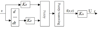
The structure of the fuzzy control system is shown in Figure 2. Among them, Fuzzy controller is the core of fuzzy control system, and fuzzy controller is made up of fuzzy input interface, knowledge base, inference mechanism and clear output interface.
(1) Fuzzy input interface
With fuzzy treatment of fuzzification interface, the controller’s quantitative input process can be completed, after that it can be then transformed into fuzzy vector. Adopting fuzzy vector to conduct fuzzy control, in the process of fuzzification, the fuzzy degree can be decided.
Figure 1. Basic process flow of video
(2) Knowledge base
Knowledge base consists of rule base and database, and all of the fuzzy control rules are put into database. The rules stored are provided to the reasoning machine for reasoning, and the control rules are established after the operation of manual input based on expert’s knowledge. And its form is carried out in accordance with the people’s intuitive reasoning to performance. The fuzzy rules are formed by the connection of relative words, and before numerical representation of fuzzification, these words must be “translated” first then they can quantize the fuzzy rules. The database stores all the fuzzy subset membership vector values. (3) Inference mechanism
Reasoning machine’s function is to conduct fuzzy reasoning. Fuzzy reasoning process should be accomplished according to the amount of knowledge base and fuzzification. The relation equation obtained through the fuzzy inference should be solved first, then got the control function part of the fuzzification.
(4) Clear output interface
After the fuzzy decision output fuzzy quantity, we still couldn’t control it. And we must firstly clear the output interface, and then turn fuzzy quantity into a precise amount.
3.2. The PID Controller
PID controller is also called three-term controller, whose transfer function is
( ) I
c p D
K
G s K K s
s
. It includes a proportional subject, an integral and a differential subjects. The
time domain output equation is:
PID controller has been widely used in industrial production process, and Part of the reason for this is that the PID controller can work in a variety of different conditions to keep good work performance. On the other hand, their functions are simple, thus they are easy to be used. For such a controller, three parameters must be determined, namely, proportional gain, integral gain and differential gain.
4. Pre-Warning and Tracking of the Image 4.1. Algorithm Model of Image Pre-Warning
In visual method of dynamics, firstly, all events should be identified verbs. If you want to learn from practice, you just need three verbs to describe all events. These three verbs are: (1) support: when the object Y is not affected by the support of object X, it will fall. In this situation, the object X is said to support the object Y. (2) connection: when two objects contact with each other, this can be called connection. (3) attachment: when two objects temporarily act as a community, we can call the relationship between them is attachment.
Based on the above verbs, in accordance with the logical connection, the complicated events can be carried out precisely. We can take the incident which the object X catches the object Y and throw it out as an example.
(Define that throw (X,Y))
(There are two sub-events(I,J)) ……I represents that X catches Y, while J represents that X throws out Y.
(logic and (when there is sub-event I, connect(X,Y)) (when there is sub-event I, attach (X,Y))
(when there is sub-event I, support (X,Y)) (when there is sub-event J, attach (X,Y))
(when there is sub-event J, logic reverse connect(X,Y)) (logic=(I the end) (J the beginning)))
Based on the above description, we design an algorithm. After DSP polling gets all input images of audio and video matrix to do the computation of the images’ contour, and then we compare the images by using dynamics. If the results comply with the things mentioned above, and then we alarm the pre-warning. Algorithm is shown in Figure 3.
Figure 3. The image algorithm of pre-warning
4.2. Image Positioning
In this article, firstly, by conducting level difference accumulative calculation against the images of original grayscale, and making the vertical edges of image outstanding, we can achieve the purpose of effective use of image gray level. And the specific equation is:
2
0
( , ) | ( , ) 2 ( 3 , ) ( 6 , ) |
d
HD x y f x d y f x d y f x d y
(2)In this equation, f x y( , ) stands for the image grey value, HD x y( , ) represents the results of differential accumulation, x stands for the abscissa value, y the ordinate value, and d the offset degree. The difference figure acquired by this method, can make the image’s edge features as prominent as possible. Especially with the processing of pixel number, the image characters within the scope of the texture feature can be “amplified” so as to provide great convenience for extracting characters in the next step.
We conduct binarization processing over the accumulated difference images, and with the adaptive threshold method in the process of dealing with images, then the complete edge image can be acquired. The formula of operation method is:
0 ( , )
( , )
255 ( , )
f x y T f x y
f x y T
(3)
In the above formula, T is the image segmentation threshold value acquired by taking Bayes’ minimum error criterion as its convergence conditions.
After the image binarization, then we scan images from longitudinal and transverse directions. For segment length of white line, we limit its impact. And the calculation steps are:
We scan a row or column, in which the number of consecutive non-zero pixel is NUM; If NUM<Tcol1(Trow1)or NUM>Tcol1(Trow1),then,the pixels of this part is zero, otherwise,the pixel value remains unchanged.
After we reset the NUM, scan the column or carry out the count of the bank, we turn to (1), until the scan of the column or the bank is completed, and then we turn to (4);
Then we move to the next column or the next bank, turn to (1) until the image scan is finished.
1
col
T (Trow1) is the preparatory set length threshold value of in accordance with a priori knowledge.
and under coordinates should be recorded as Lefti, Righti, Topi and Bottomirespectively. AnD
then we define them as candidate-rectangular-areas so that the length and width of each rectangular area can be calculated by:
i
W=Righti-Lefti (4)
i
H =Topi-Bottomi (5)
Then, for each candidate rectangle image we carry out the difference calculation in the
vertical and horizontal directions, and finally we acquire the vertical projection image VP xi( )of
the vertical difference image:
within a certain interval the width of the image characters presents certain changes. However, because of all kinds of noises, the spacing between the characters can conduct interference so that its regularity is not obvious. Therefore, in the Interval [0, Max] we conduct the horizontal scanning through line y = Scan against VP xi( ) from 0 to Maxi based on the corresponding
Intervali. We record the number of consecutive elements in VP xi( )which are greater than the
scan line-Scan. Its obvious surface feature is the segment length of multiple scan lines. And then for the corresponding range of length changes, we accumulate and count the length and occurrence frequency of all the scanned lines between [0, Max]. Only when the length of the line frequency is greater than a certain value (this article supposes that the certain value is 5, the Intervali is 1), and the area is the true image area. After the above procedures, normally, it is
able to eliminate all the non-image candidate areas. By this way we can realize the positioning and selection in vertical direction of the image area.
4.3. Image Recognition
Due to the different shooting angles, the acquired images often have tilt, which leads to the difficulties in image character elaboration and identification in subsequent steps. So we can use the Hough transform to detect the tilted border or the one that though not tilted but over a specific length. And also the Hough transform can be used to detect the edges which are in the same situation so as to complete the correction process against the tilt images.
After the binary image of inclination correction of target zone is acquired, the numbers, letters, Chinese characters and related characters’ features in images should be extracted. In this process, the first thing is to refine the image processing. And its purpose is to make the process of extracting features more convenient.
For image refining process, which is after the operation, then we turn the binary image with certain width area into a skeleton with the width of only pixel. Refinement of the image is a very important and critical operating process while conduct pattern recognition and image analysis. By refinement, the skeleton image acquired could provide a clear and concise form for the following new analysis and image processing. The skeleton acquired makes it convenient for understanding and analyzing the image in a higher level. The requirement of the refinement of the image processing is mentioned as follows. First, the skeleton acquired shall be ensured of the topological structure and connectivity of the original image; Second, the skeleton acquired will better present concise structure of the original image; Third, iterations involved should appear as few as possible, that is to say, the processing speed should be as quick as possible; Fourth, the number of iterations used should be less as far as possible, that is to say, its processing speed should be quick as much as possible; Fifth, its anti-noise performance should be good.
In the research process of this paper, we make use of the American Y.Y.Z HANG and the refinement algorithm put forward by P.S.P.W, professor ANG. And the refinement algorithm is shown as follows:
conditions, deletes it from the original image: (1) P1 = 1; (2) < = 2 B (Pl) < = 6; (3) A (Pl) = 1; (4) P2 * P4 * P8 = 0 or P11 = 1; (5) P2 * P4 * P6 = 0 or P15 = 1, as Table 1.
Before the identification, the characteristics of the numbers and letters in the image refined should be extracted to analyze, and make sure that by referring these characteristics, different kinds of numbers, letters can be distinguished. The principles of analyzing the characteristics are mentioned as follows. First, independence is required, that is to say, there is no correlation among characteristics; Second, differences should be maintained among characteristics, and there should be significant differences among different categories of object; Third, their numbers should be small; Fourth, the reliability should be maintained, and it means the closeness between the same kind of objects.
Then, we take the numbers as example to analyze. According to the appearance features of numbers, we extract four characteristics. First, on the horizontal line XR = nR/widthR, the nR represents the number for horizontal pixel points, and widthR represents for image pixel level of individual letters. If XR > 0.5, there is one horizontal line; Second, on the vertical line YC = nC/widthC, the nC represents for the vertical pixel number, and widthC represents vertical image pixels of a single letter. If YC > 0.5, there is one vertical line; Third, the number of horizontal lines. We draw horizontal a line, and count the number of the cross points between image and the horizontal line; Fourth, the vertical lines’ number. We draw a line vertically, and count the number of the cross points between the images and this vertical line. In the judging process, first of all, we should group all the horizontal lines into horizontal ones and others that are not, for example, A. with horizontal lines (2, 4, 5, 7); B no horizontal line (0, 1, 3, 6, 8, 9). For the group A, we distinguish it first according to the lateral position (upper horizontal line, bottom horizontal line) the line, and then according to the presence vertical bar; For the group B, we distinguish in accordance with the presence of vertical lines, horizontal lines and vertical lines.
4.4. Image Tracking Based on PID
If we design the fuzzy rules, we can further design a reliable high-speed ball. And we take the system error eand error change eas the input statement variables. The structure is shown in Figure 4.
Table 1. Algorithm template P10 P11 P12 P13 P9 P2 P3 P14 P8 P1 P4 P15 P7 P6 P5 P16
Figure 4. The fuzzy control block diagram
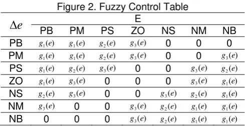
Based on fuzzy control rules, suppose that the language variable of deviation e is E, the language values of relevant fuzzy subset A are “positive more (PB)”, “positive” (PM), “positive less” (PS), “zero”(ZO), “negative less” (NS), “negative”(NM), “negative more” (NB). In addition, suppose that the language variable of deviationeisE, the language value of the corresponding fuzzy subset B and fuzzy subset A maybe the same. As in T – S(Takagi and Sugeno)fuzzy model, namely, the contain equation : if e= A and e= B , thenUf =g e( ), and A
and B are A fuzzy subsets, g e( )is the continuous function of e. Based on the model, we can acquire the fuzzy control table, as shown in Table 2. In the table,g e1( )K eu ,g e2( )=0.7K eu ,g e3( )=0.35K eu . Because the fuzzy adaptive mechanism
output isUf , we can get-
f
U =f e( ,e) K eu (7)
In the above equation, f represents the nonlinear relationship.
At the same time, because that the fuzzy adaptive controller output isUf, and Uf is the
( ) p ( ) i ( ) d ( ) /
K K T and Ti are integral time constants, and Td is differential time constant. Therefore, the
output of fuzzy adaptive PID is:
1 f
At the same time, in order to better promote PID’s function, we also can set the scale factor according to the adaptive parameter correction of the system deviation eand deviation variablee. Deviation principle is mentioned as follows. When the deviatione and the deviation variable e are larger, the smaller values of Ke, Ke and the lager values of Kp,Kishould be
taken, so as to reduce the resolution ratio of deviation eand deviation variable e; When the system is in a steady state, deviation eand deviation variable e are smaller, the larger values of Ke,Ke and the smaller values of Kp,Kishould be taken, so as to increase the resolution
ratio of deviation e and deviation variable e. Parameter correction module can easily realize the calculation of multiple parameter correction based on the deviation eand the deviation variablee, and the equations areKe Ken,Ke Ken,Kp Kp/nand Ki Ki /n. At the
same time, because of the above situations, the integral time constant can be acquired according to the differential time constant, namely, Ti =
a
Td.We take the above equation (7) and (9) respectively into the equation (8). And there is
1
Form equation (10) we can know that, the gain of a fuzzy adaptive PID controller actually is a kind of nonlinear function in a system state, and it can play the ratio function of dynamical adjust controller.
5. Model Performance Analysis 5.1. Fuzzy Control Simulation
We carry out simulation tests by using MATLAB which installs fuzzy adaptive controller and using the ones which don’t install the controller, and then we compare the two situations. The transfer function of controlled object is:
The response results of unit steps is shown in Figure 5.
Figure 5. Fuzzy PID and conventional PID control system simulation
We can know from the above curves that the system dynamics of fuzzy adaptive PID control can quickly response. The system dynamics of conventional PID control just response slowly. And there is oscillation phenomenon (time period: 0.52 seconds to 0.75 seconds).
5.2. Image Recognition Simulation
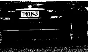
We carry out vehicle license recognition and tracking simulation test proposed in this paper, as Figure 6. The following results can be acquired. After binarization processing against the above picture, the following result can be acquired, as Figure 7.
Figure 6. License plate grayscale Figure 7. License plate binarization
Then, we carry out the retrieval step against the license plate candidate area, and we can get the following picture, as Figure 8. The license plate location finally is got. From the above simulation tests, we can see that the algorithm method proposed in this paper is practical and effective, and it can achieve good recognition and tracking, as Figure 9.
6. Conclusion
In this paper, based on the analysis of image detection and tracking principles proposed image recognition based PID fuzzy control and tracking algorithm.The simulation results show that the proposed algorithm has good effect for vehicle license plate image recognition and positioning. Besides, when using the fuzzy adaptive PID control, the system dynamic response is fast. It is not only within the quantity, but also has no steady-state error. so it has good function which can carry out the tracking and control on images.
Acknowledgements
This study was supported by Jiangxi province science and technology support program: Research on the architecture and technology of vehicle networking for intelligent traffic (20133BBE50036).
References
[1] Huang D. Radial basis probabilistic neural networks: model and application. International Journal of Pattern Recognition and Artificial Intelligence. 1999; 13(7): 1083-1101.
[2] Helo P, Szekely B. Logistics information systems: an analysis of software solutions for supply chain co-ordination. Industrial Management & Data Systems. 2005; 105(1): 5-18. [3] Yang J, Zhang D, Frangi A F, et al. Two-dimensional PCA: a new approach to
appearance-based face representation and recognition. IEEE transactions on pattern analysis and machine intelligence. 2004; 26(1): 131-137.
[4] Min S H, Lee J, Han I. Hybrid genetic algorithms and support vector machines for bankruptcy prediction. Expert systems with applications. 2006; 31(3): 652-660.
[5] Bhargavi VR, Senapati RK. Bright Lesion Detection in Color Fundus Images Based on Texture Features. Bulletin of Electrical Engineering and Informatics. 2016; 5(1): 92-100.
[6] Lin C J. Projected gradient methods for nonnegative matrix factorization. Neural computation. 2007; 19(10): 2756-2779.