Fuzzy Gain Scheduling of PID (FGS-PID) for Speed Control
Three Phase Induction Motor Based on Indirect Field
Oriented Control (IFOC)
Indra Ferdiansyah, Era Purwanto, Novie Ayub Windarko
Politeknik Elektronika Negeri Surabaya Kampus PENS, Jl. Raya ITS, Sukolilo Surabaya
[email protected], {era,ayub}@pens.ac.id
Abstract
This paper propose about using PID control system based on Kp, Ki, and Kd parameter determination with scheduling process from fuzzy logic. Control system is used to arrange speed of three phase induction motor using IFOC method. This method can be minimized the main problem from speed control of induction motor which is a transient condition. The robustness validation from this system use testing process of dynamic speed which is compared with the other control system to know the system performance in transient condition such as (rise time, overshoot, undershoot and settling time). The result shows using the proposed system has better performance responses which is requiring 0.001 seconds time in transient condition up to steady state condition without overshoot and undershoot problem.
(D.C) machine was largely used in the field of the variable speed applications, where torque and flux are naturally decoupled and can be controlled independently by the torque producing current and the flux producing current. Since Blashke and Hasse have developed the new technique known as vector control [1-4], the use of the induction machine becomes more and more frequent. This control strategy can provide the same performance as achieved from a separately excited DC machine, and is proven to be well adapted to all type of electrical drives associated with induction machines[5].The vector control technique has been widely used when high performance rotary machine drive is required, especially the Indirect Field Oriented Control (IFOC) that is the most effective vector control of three phase induction motor due to the simplicity of designing and implementation [6]. Decoupled torque and flux control in IFOC of induction machines permits higy dynamic response.While, induction motor control cann’t apart from its previous condition. The real nonlinear characteristic from motor and the modification parameter from control caused to the modification value in control process when the time of trancient condition was toward to the steady state in set point achievement. Using appropriate control system can be minimized its problem.
The most widely used controller in the industrial applications is the PID-type controllers because of their simple structures and good performances in a wide range of operating conditions [7]. In the literature, the PID controllers can be divided into two main parts: In the first part, the controller parameters are fixed during control operation. These parameters are selected in an optimal way by known methods such as the Zeigler and Nichols, poles assignment…etc. The PID controllers of this part are simple but cannot always effectively control systems with changing parameters or have a strong nonlinearity; and may need frequent on-line retuning [8]. In the second part, the controllers have an identical structure to PID controllers but their parameters are tuned on-line based on parameters estimation of the process. Such controllers are known as adaptive PID controllers [2].
The application of knowledge-based systems in process control is growing, especially in the field of fuzzy control [9-12]. In fuzzy control, linguistic descriptions of human expertise in controlling a process are represented as fuzzy rules or relations. This knowledge base is used by an inference mechanism, in conjunction with some knowledge of the states of the process (say, of measured response variables) in order to determine con trol actions. Although they do not have an apparent structure of PID controllers, fuzzy logic controllers may be considered nonlinear PID controllers whose parameters can be determined on-line based on the error signal and their time derivative or difference [11].
demonstrated in this paper that human expertise on PID gain scheduling can be represented in fuzzy rules. Furthermore, better control performance can be expected in the proposed method than that of the PID controllers with fixed parameters on dynamic conditions. The investigation of transient condition (involve rise time, overshoot, undershoot, and settling time) in speed of dynamic is presented section 2. The comparation between FGS-PID and other control is presented section 3.
2. RELATED WORKS
The theory of Fuzzy Gain Scheduling-PIDwas firstly developed by Zhen-Yu Zhao, Masayoshi Tomizuka, and Satoru Isaka in 1993.UsingFuzzy gain scheduling could be used to determine gain parameters of PID control.PID is one of popular control in industrial because it has simple design,robust control andalso easy to be implemented. However, parameter of gain PID is difficult to be determined which needs re-tuning to get a good result. One of developed tuning methodsis Ziegler Nichols that is simple indetermining ofKp gain, Ki, and Kd of PID parameters [7].
Fuzzy logic was presented by Prof. L.Zadeh in 1965 from California schedule parameter gain (p), kd’ is used to schedule parameter gain (Td), and α is used to schedule gain (Ti).By applying gain system scheduling of PID parameter, PID tuning process is easier to do in stabil or unstabil condition. In Zhao and friends’ presentation, also comparing the output response system of FGS-PID control, PID-ZN, and Kitamori. Thecomparations are done from output control system for second, third, and fourth order. The result shows that FGS-PID has more optimal response because it can reduce overshoot condition and osilationsystem[13].
Then, Bousserhane presents optimal fuzzy gains scheduling of pi controller for induction motor speed control. To overcome the disadvantages of PID controllers and FLC, we propose in this paper a combination between them together. PID parameters controller can be tuned on-line by an adaptive mechanism based on a fuzzy logic for induction machine speed control. Design of an optimal fuzzy gain scheduling of PI controller combines the merits of the sliding mode control and the fuzzy inference mechanism is proposed. A fuzzy gain scheduling of conventional PI controller is investigated, in which the fuzzy logic system is used on-line to generate the PI controller parameters [2].
tuning process of PID control to get a better response result in transient condition at speed of dynamic.
3. ORIGINALITY
The constribution of this paper is to implement speed control of induction motor based on PID with scheduling and reasoning from fuzzy logic control to obtain parameter system which is suitable with determined condition using IFOC method. Using the proposed method can be minimized the problem of induction motor rotation in transient condition which has non-linear characteristic. The principle of fuzzy gain scheduling is used to arrange the PID gain that is appropriate with the declared condition. The output of control system is control signal which is used for IFOC system in control of induction motor system. The implementation of proposed IFOC method is simply to apply which is using control system based on vector technique. The vector technique is oriented to the field control which can be controlled the torque unit and flux separately. This system is usually called by decoupled system. the modification of flux and torque can be influenced to the motor rotation which is represented as current and speed modification.
The parameter modification from control system can be decreased the performance of control system which is showed from motor responses in transient condition. Using FGS-PID is one of solution to minimize this problem. The control design is arranged for 0 – 1000 Rpm speed which can be given the better result in modification parameter condition. Verification process and the robustness test of this sytem is used dynamic speed control sytem which is observed in transient condition involve rise time, overshoot, undershoot and time settling.
4. SYSTEM DESIGN 4.1 RESEARCH METHOD 4.1.1 PID Controller
PID control is a combination from three methods; those are proportional control, integral, and derivative. Combination of these methods can be used to minimize disadvantage of each controls. Proportional control (P) has function to accelerate up to set point condition, but it can cause overshoot. Disadvantage of control (P) can be solved by adding integral control (I) that functions to reduce overshoot, but system will be slow. So it needs derivative control (D) to accelerate system. But sometimes, it causes osilation condition before getting steady state. The equation of PID control is given to this following equation [13]:
Figure 1. Blok of diagram PID controller
PID control has gain parameters that can be influencedto the control; those are Kp, Ki, and Kd. The values of gains can be used to get a good control result. However, it is difficult to be determined that needs re-tuning to get a good result. Ziegler-Nichols(ZN) method is one solution to determine a difficult a gain value of good control. This method also can be used for tuning process.
ZN is one of tuning method that is used for deciding PID parameters. First tuning process is setting Kp, and then set the value of Ti to be unlimited, and set the value of Td to be zero. Then, increase the value of Kp until the value of oscillation and amplitude are the same. Gain that creates oscillation condition is gain Ku and oscillation period of full wave is Pu. The value of Ku
and Pu are used for getting the value of Kp, Ki, and Kd. ZN tuning rule is shown in table 1 [13].
Table 1. Rule of Ziegler-Nichols Method
Type of Controller
Proportional (P) 0.5 - - Proportional Integral
(PI)
0.45
1.2
-
Proportional Integral Derivative (PID) 0.6
2 8
4.1.2 Fuzzy gain scheduling-PID
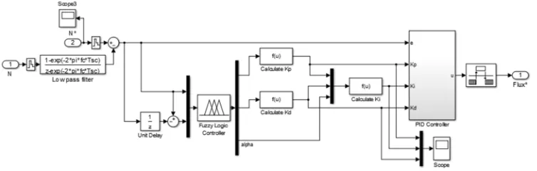
On the Fig 2 shows the PID control system with a fuzzy gain scheduler. The approach taken here is to exploit fuzzy rules and reasoning to generate controller parameters.
Figure 2.Blok of diagram FGS-PID controller
It is assumed that Kp are in prescribed ranges [Kp min, Kp max] and [Kd min, Kd max] respectively. The apropriate ranges are determined experimentally and will be given in equation (4). For convenience, Kp and Kd are normalized into the range between zero and one by the following linear transformation [7]:
Kp’ = (Kp– Kp min) / (Kp max – Kp min) (2)
Kd’ = (Kd– Kd min) / (Kd max – Kd min) (3)
In the proposed scheme, PID parameters are determined based on the current error e(k) and its first difference Ae(k). The integral time constant is determined with reference to the derivative time constant and the integral gain is thus obtained by
Ki = Kp/(αTd) = Kp2/(αKd) (4)
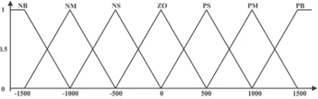
The parameters Kp’, Kd’, α are determined by a set of fuzzy rules of the form. The membership functions (MF) of these fuzzy sets for error [e (k)] and delta error [Δe (k)] are shown in Fig. 3. In this figure, N represents negative, P positive, ZO approximately zero, S small, M medium, B big. Thus NM stands for negative-medium, PB for positive big, and so on.
S MS M B Figure 4. Membership function for Kp’ and Kd’
Figure 5. Output of Membership function α
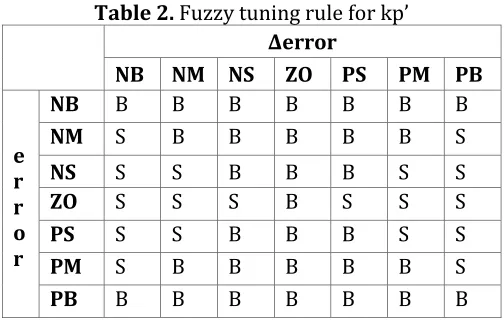
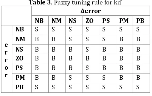
The rule base of Fuzzy gain scheduler to deremine PID parameter shown in table 2, 3, and 4 [2].
Table 2. Fuzzy tuning rule for kp’
Δerror
NB NM NS ZO PS PM PB
e r r o r
NB B B B B B B B
NM S B B B B B S
NS S S B B B S S
ZO S S S B S S S
PS S S B B B S S
PM S B B B B B S
Table 3. Fuzzy tuning rule for kd’
(Kp max, Kp min) and (Kd max, Kd min) is obtained from this following equation:
= 0.32 , $% = 0.6 (8)
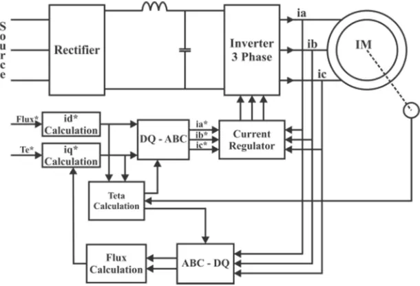
4.1.3 Indirect Field Oriented Control (IFOC)
The principle of indirect field-oriented control system of an induction motor is that the d-q coordinate's reference frame is locked to the rotor flux vector, this results in a decoupling of the variables so that flux and torque can be separately controlled by stator direct-axis current ids, and quadrature-axis current iqs, respectively, like in the separately excited dc machine. To perform the alignment on a reference frame revolving with the rotor flux requires information on the modulus and position of the rotor flux [25].
Figure 6. Block of diagram IFOC for Induction Motor
Rotor flux and torque can be separately controlled by stator direct-axis current (ids) and quadrature-axis currents (iqs) in sequence. Large quadratureaxis current reference (iqs*) can be calculated by reference torque Te * using the following equation:
()∗ = +,∗+-∗../
0∗
12∗
3/∗ (10)
Lr is the rotor inductance, Lm is the mutual inductance and λr is the flux linkage rotor estimation which is derived from this equation:
45 = .9:;0678/< (11)
=5 = .>// is the time constants of rotor. The number of direct-axis stator
current reference ()∗ is based on the flux reference input 45∗ as follow:
∗) = .3∗
The angle of flux rotor θe for coordinate transformation which is derived from rotation speed of rotor ωm and slip speed ωsl calculation as follow:
?@ = AB+ A)C (13)
Slip speed is calculated from stator current reference ()∗ with this following motor parameter:
A)C = .30 /
∗ ∗>.//∗ ()∗ (14)
Reference current DE∗dan E∗ converted into a reference-phase flow FE∗ ,GE∗ , HE∗ using the following equation (10) which will be the input current regulator. Then the flow regulator will process the reference phase current into a signal which triggers will control the inverter.
I F
4.2 Speed Control for three phase induction motor
4.2.1 Implemetationmodelling IFOC without Speed Control
Figure 7. Block diagram of design system
In this paper proposed simulation model of three-phase induction motor with the implementation of Indirect Field Oriented Control (IFOC) system. Parameter of three-phase induction motors that was used in this simulation:
Table 5. Specification of induction motor
No Motor Parameter Specification
The system IFOC the transformation stationer frame into rotational frame using Clark and Park Transformation. Clark transformation is used to modify three-phase stationary (ia, ib, ic) to be two-phase stationary (iα, iβ). While,
Park Transformation modify two-phase stationary to the two phase rotational (id, iq) that was illustrated in Fig. 10.
Figure 8. Model of Indirect Field Oriented Control (IFOC)
4.2.1 Design of Fuzzy Gain Scheduling PID
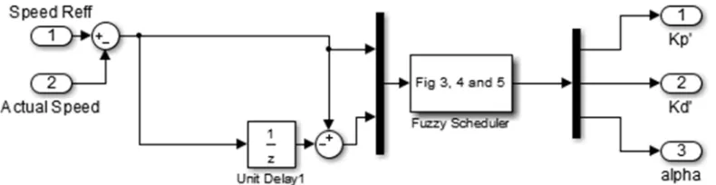
The design of Fuzzy scheduler for FGS-PID using two input values, those are error value and delta error value. The output from the result of scheduler fuzzy is also used to this system based on gain value as the PID control basic calculation. Gain value is determined by scheduling process which can be used to obtain the best and the compatible gain from the operating condition. Scheduling system is also used to determine gain value when there is modification parameter in control system. Fuzzy gain scheduler model of this system is ilustrated in Fig.9.
Figure 9.Block of diagram fuzzy gain scheduler
5. EXPERIMENT RESULT AND ANALYSIS
5.1 Simulation Result IFOC without Speed Control
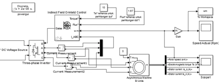
The simulation system of IFOC without speed control of three-phase induction motor using IFOC, was depicted in Fig. 10.
Figure 10.Simulationspeed control of three phase induction motor using IFOC
The output of response speed control using IFOCcan be got speed motorin 350 Rpm, 400 Rpm, and 450 Rpmthat was ilustrated in the following below:.
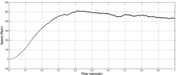
Figure 11.Simulation result speed controlwithIFOC on the speed motor 350 Rpm
The simulation result(Fig.11) can see the output response system. The rise time value to get speed in 350 Rpm was 0.23 second. The maximum overshoot is 28 %, and time settling 0.89 second before steady speedcondition.
Rise time Overshoot
Figure 12.Simulation result speed control with IFOC on the speed motor 400 Rpm
While, the number ofrise time to get speed 400 Rpm was needed 0.256 second that has maximum overshoot 29 %, and time settling 0.74 second before condition steady speed, depicted in Fig.12.
Figure 13.Simulation result speed control with IFOC on the speed motor 450 Rpm
In Fig.13 speed 450 Rpm was needed 0.23 second rise time, 28 % maximum overshoot, and time settling 0.93 second before condition steady speed.
5.2 Simulation Result IFOC with Speed Control FGS-PID
Figure 14.Simulation of IFOC using speed control FGS-PID
In Fig. 15, showsthe diagram block of speed control FGS-PID for three-phase induction motor based on IFOC.
Figure 15.Block of Speed ControlIFOC using FGS-PID
Figure 16.Simulation result FGS-PID at speed modification 300 Rpm – 600 Rpm
The performance result from FGS-PID control for three phase induction motor of IFOC based is using set point variable as shown in Fig.20. The sytem responses can be analyzed or observed with 0.1 seconds sampling time as follows:
Table 6.Result observation transien condition at speed control using FGS-PID Speed (Rpm)
300 600
Rise time (s) 0.0135 0.0132 Overshoot (%) 0 0 Undershoot (%) 0 0 Settling time (s) 0.014 0.0143
The next condition, we declared 400 Rpm setpoint and 0.05 seconds steady state condition at the runned simulation. It will be reduced up to 200 Rpm setpoint and 0.1 seconds in steady state condition. For the last, the setpoint is set in 150 Rpm and 0.1 seconds steady state condition.
Figure 17.Simulation result FGS-PID at speed modification 400 Rpm – 200 Rpm
Table 7.Secondresult observation transien condition using speed control FGS-PID
Speed (Rpm) 400 200 Rise time (s) 0.017 0.0085 Overshoot (%) 0 0 Undershoot (%) 0 0 Settling time (s) 0.017 0.0173
From the observation above is known that FGS-PID control has a better response can be solve the problem in transient condition to get steady state
condition only takes less than 0.01 seconds without getting overshoot and undershoot.
5.3The comparison proposed FGS-PID with other speed control
FGS-PID control are proposed to be used to improve transient conditions in implementation IFOC for induction motors to achieve steady state when modified parameters.By performing IFOC methods for induction motor can be to modify characteristic nonlinear similarly of DC motor which is expected to control systems designed to obtain optimal results because the process is controlled in linear conditions.Some control used on an induction motor, majority want to get good result to achieve setpoint so ignore the transient condition other. The performance result from the comparison between FGS-PID, PID-Zn and FuzzyBackstepping for three phase induction motor of IFOC based is using set point variable as shown in Fig.18. The sytem responses can be analyzed and observed with 0.1 seconds sampling time as follows:
Figure 18. Comparison between FGS-PID, PID-ZN, and Fuzzy Backstepping at speed of dynamic
Table 8.Theresult observation transien condition on speed control
Table 9.The result observation transien condition on speed control PID-ZN
Table 10.The result observation transien condition on speed control Fuzzy-Backstepping
5.4 Scheduler of parameter gain on PID control
The results of the scheduling gain of PID parameters are presented below:
Figure 25.Scheduler of gain proportional for the control of dynamic speed 250 Rpm, 500 Rpm, 100 Rpm, and 300 Rpm
Figure 26.Scheduler of time constant integral for the control of dynamic speed 250 Rpm, 500 Rpm, 100 Rpm, and 300 Rpm
On the graph in Fig 25, Fig 26, and Fig 27,it can be observed that scheduling gain process will be performed when control process parameter is modified, so it still gets a good result. From the results above with a sampling time of 0-1 second, it is observed on performed scheduling process. At time 0 – 0.25 second with setpoint 250 rpm, then obtained value gain of proportional (Kp) is 8,256, time integral constant (Ti) is at 1.474, and time derivative constant (Td) is 0.2455. When there is a modifiedsetpoint to be 500 rpm at 0.25 - 0.5 seconds,it is performed the scheduling again to get a suitable value.(Kp) is 8.2537, (Ti)is 1.486, and (Td)is 0.2437. And then, when setpointis100 Rpm at time 0.5 - 0.75 second, the result of scheduling (Kp)is 8.2577, (Ti)is 1.478, and (Td)is 0.2457. When the last condition, setpointis 300 Rpm at time 0.75 - 1 second, (Kp)is 8.255, (Ti)is 1.478, and (Td)is 0.24457.
6. CONCLUSION
Design of proposed FGS-PID in the three-phase induction motor speed control using IFOC methods can provide good results. It is verified with testing a reliability of control system on dynamic speed. With this method of observation in transient conditions (involve rise time, overshoot, undershoot, and settling time) it can be knownthat the performance of the control system is in good condition although the parameters of process control is modified, because it has a fast response below 0.0004 second to achieve a steady state condition without getting overshoot and undershoot. The other advantage of FGS-PID based on IFOC in induction motors is, it can have linearization characteristic of the motor, so it can be easy to control as DC motor. Thus, when getting linear conditions, FGS-PID control can more easily generate optimum performance even though applied to condition of fluctuation.
ACKNOWLEDGEMENTS
The first I extend thanks to “ALLAH SWT” always give love and help me in researcher, secondly my family is always pray for me and then i thanks to“Kementerian Riset, Teknologi dan Pendidikan Tinggi Republik Indonesia” which was approve the scholarship freshgraduate program in Study Program of Applied Master’s Degree Electrical Engineering at Politeknik Elektronika Negeri Surabaya and also the all friend in “Tanggul Islamic Centre” who have helped this research better.
REFERENCE
[1] J.P. Hautier J.P. Caron, Modeling and Control of Induction Machine, Technip ed., 1995.
[2] I.K. Bousserhane, A. Hazzab, M. Rahli, B. Mazari, and M. Kamli "OPTIMAL FUZZY GAINS SCHEDULING OF PI CONTROLLER FOR INDUCTION MOTOR SPEED CONTROL ," Acta Electrotechnica et Informatica , vol. 7, no. 1, 2007.
Industry application, vol. 26, no. 3, may 1990.
[4] L. Baghli, "Contribution to Induction Machine Control: Using Fuzzy Logic, Neural Networks and Genetic Algorithms," Henri Poincare University, Doctoral Thesis 1999.
[5] M.A. Ouhrouche, C. Volet "Simulation of a Direct Field-Oriented Controller for an Induction Motor Using Matlab/Simulink Software Package," in IASTED, USA, 2000.
[6] Salah Eddine Rezgui and Hocine Benalla, "High Performance Controllers for Speed and Position Induction Motor Drive Using New Reaching Law,"
International Journal of Instrumentation and Control Systems (IJICS), pp. 31-46, 2011.
[7] Zhen-Yu Zhao, Masayoshi Tomizuka, and Satoru Isaka, "Fuzzy Gain Scheduling of PID Controllers," IEEE Transactions On Systems, pp. 1392 - 1398, 1993.
[8] Kuo. B.C, Automatic Control System, 5th ed. Englewood Cliffs: Prentice Hall, 1987.
[9] M.J. Rabins,and D.M, Auslander Y. Takahasi, Control and dynamic systems. Menlo park: Addison Wesly, 1970.
[10] hang H.S and J Gertler, "An instability indicator for expert control," IEEE, vol. 6, pp. 34-42, 1986.
[11] C.C Hang, and W. K. Ho K.J. Astrom, "Refinements of the Ziegler Nichols tuning formula," in IEE, Pt.D, 1991, pp. 111-118.
[12] M. Sugeno, Industrial aplications of fuzzy control. Amsterdam, Netherland: North-Holland, 1985.
[13] II Munadhif , Aulia Siti. A, dan A. Agus M, "Perancangan sistem kendali kestabilan rolling kapal perang kelas sigma saat bermanuver menggunakan Fuzzy Gain Schedulling-PID, Tesis, Institut Teknologi Sepuluh Nopember, (Surabaya),2015" controllers," Trans ASME, vol. 64, pp. 759-768, 1942.
[17] Gawthrop P. J and P.E. Nomikos, "Automatic tuning of commercial PID controllers for single-loop and multiloop aplications," IEEE Control Sys. Mag, vol. 10, pp. 34-42, 1990.
[18] S. Omatu, and H. Ishihara T. Yamamoto, "A construction of self tuning PID control system," Trans.SICE. Japan, vol. 25, pp. 39-45, 1989.
[19] C.C. Lee, "Fuzzy logic in control system: Fuzzy logic controller part 1,"
[20] T.J Procyk and E. H. Mamdani, "A linguistic self-organizing process controller," Automatica, vol. 15, pp. 15-30, 19791.
[21] M. Sugeno, Industrial aplications of fuzzy control. Amsterdam, Netherland: North-Holland, 1985.
[22] Takagi. T and Sugeno. M, "Fuzzy identification of systems and its aplications to modeling and control," IEE Trans, vol. SMC-15, pp. 116-132, 1985.
[23] Arun Kumar R, "Indirect Field Oriented Control of Induction Motor Using Fuzzy Logic," in ResearchGate, 2012.
[24] Era Purwanto , Gigih Prabowo, Endra Wahyono, dan M. Machmud Rifadil, "Pengembangan Model Motor Induksi sebagai Penggerak Mobil Listrik dengan Menggunakan Metode Vektor Kontrol," Jurnal Ilmiah ELITE Elektro (Institut Teknologi Sepuluh Nopember Surabaya), pp. 67-72, 2011.
[25] Rizana Fauzi , Dedid Cahya Happyanto, and Indra Adji Sulistijono, "Fast Respon Three Phase Induction Motor Using Indirect Field Oriented Control (IFOC) Based On Fuzzy-PI," IES, 2014.
[26] Gagan Singh Gurmeet Singh, "Modeling and Simulation of Indirect Field Oriented Control of Three Phase Induction Motor using Fuzzy Logic Control," International Journal of Engineering Research & Technology (IJERT), vol. 3, no. 8, pp. 1126-1130, August 2014.
[27] DR.V. Rajasekaran, DR.I.Gerald C, N. Panner S M. Arul Prasanna, "Modeling, Analysis and IFO COntrol Method For CSI FED 3 Phase Induction Motor Drive," Journal of Theoritical and Applied Information Technology, pp. 444-451, 2014.
[28] Bilal Akin, State Estimation Technique For Speed Sensorless Field Oriented Control of Induction Motors.: School of Natural and Applied Sciences, 2013.
[29] Ananda kumar Akkaraapaka and Dherendra singh, "The IFOC Based Speed Control of Induction Motor fed by A High Performance Z-Source Inverter," IEEE, 2014.