ISSN: 2088-8708, DOI: 10.11591/ ijece.v 8i4.7290 1939
Fuzzy Gain Scheduling PID Control for Position of
The AR.Drone
Agung Prayitno1, Veronica Indrawati2, Ivan Immanuel Trusulaw3 Department of Electrical Engineering, University of Surabaya (UBAYA), Indonesia
Article Info ABSTRACT
Article history: Received May 31, 2017 Revised Oct 24, 2017 Accepted Mar 14, 2018
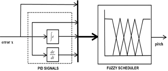
This paper describes the design and implementation of fuzzy gain scheduling PID control for position of the AR.Drone. This control scheme uses 3 PID controllers as the main controller of the AR.Drone, in this case to control pitch, roll and throttle. The process of tuning parameters for each PID is done automatically by scheduling determined by Takagi-Sugeno-Kang (TSK) fuzzy logic model. This paper uses five function sets of PID parameters that will be evaluated by fuzzy logic in order to tune PID controllers. Error position (x,y,z), as inputs of controller, enters the PID Signal block yielding the ouputs in term of error, integral error and differential error. These signal become the inputs of the fuzzy scheduler to yield outputs pitch, roll and throttle to the AR.drone. The control scheme is implemented on the AR.Drone to make it fly to forming a square in the room. The experimental results show that the control scheme can follow the desired points, and
TB.2 Building, Raya Kalirungkut 60293 Surabaya, East Java, Indonesia. Email: [email protected]
1. INTRODUCTION
The use of quadrotor to assist human activities has become more diverse. The examples are the use of quadrotor for news coverage activities, assisting agriculture, disaster evacuation, product promotion and entertainment. Research using the quadrotor is also increasingly masive in various universities in the world both in terms of hardware and software. Many quadrotor platforms for research purposes are sold on the market with a range of low to expensive prices with specific technical specifications.
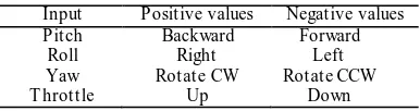
This research uses the AR.Drone 2.0 Elite Edition which is a product of Parrot. The AR.Drone is relatively inexpensive and is equipped with onboard electronics that have a motherboard, a processor, a Wi-Fi chip, 3 axis gyroscope, 3 axis accelerometer, a sonar altimeter, and a front camera and bottom. It is also equipped with a real-time operating system that can perform multiple tasks simultaneously, such as communication with a PC via Wi-Fi, video data sampling, sensor acquisition, image processing, state estimation and closed loop control. With this communication, it is possible to transmit control commands and request navigation data of drones in the form of actual roll value, sideward speed, actual pitch value, forward speed, actual yaw rate value, yaw value, vertical rate value and altitude value [1]. Maneuver of the AR.Drone can be controlled with 4 pieces of control command that pitch, roll, yaw and throttle that has values between -1 and 1 as shown in Table 1.
Int J Elec & Comp Eng, Vol. 8, No. 4, August 2018: 1939 –1946
clusters. NavData VI sends UDP packets to the Navdata output who ordered AR.Drone to send sensor’s data to IP address of the computer.
Table 1. Control Command of AR.Drone
Input Positive values Negative values
Pitch Backward Forward
Roll Right Left
Yaw Rotate CW Rotate CCW
T hrottle Up Down
State VI is used to estimate x, y, z position of the Navdata. Some researchers noted having designed PID and Fuzzy controller on the AR.Drone. Prayitno, et a l. in [3] designed 2 fuzzy controllers to control the x and y position using pitch and yaw. Indrawati, et a l. in [4] and [5] is designed and implemented three pieces of fuzzy logic control to control the position of x, y, z using of pitch, roll and vertical rate of the AR.Drone. They compared various schemes of fuzzy control to position control. Prayitno, et a l. in [6] is designed conventional PID control and compared with fuzzy control scheme designed by Indrawati in [5]. Tang in [7] designed a PID controller for waypoint navigation applications and trajectory tracking and vision-based controller for a variety of formation flying. Abbas, et a l. in [8] is designed controls for tracking formation quadrotor where the PID controller is implemented in quadrotor leader and directed Lyapunov controller is implemented on the followers. The artificial fish swarm algorithm is used for dynamics optimization of the parameters controllers. Seidabad, et a l. in [9] modelled the motion of all quadrotor with Simulink. They are using two types of controllers, which are PID controller and combination of fuzzy -PID controller. The simulation results showed that the hybrid fuzzy-PID controller is more suitable when there has a turbulence. Gautam, et a l. in [10] designed a self-tuning PID controller using EKF algorithm that is implemented on quadrotor for attitude and position control of the quadrot or. Ammozgar, et a l. in [11] implemented Fuzzy PID Gain-Scheduled to cope with the possible failure of the actuator quadrotor. The two actuator failure schemes are designed, which are the failure of all actuators and single actuator. Prayitno, et a l. in [12] implemented other control scheme, H-Infinity, to control pitch and roll of the AR.Drone. Hazzab i, et a l. in [13] implemented adaptive FLC-PI, where PI controller parameters are adjusted by fuzzy gain scheduling, to control an induction motor. Syed, et a l. in [14] applied fuzzy gain scheduling PI control based
on the system’s operating conditions for controlling engine power and speed of a power-split HEV in the
applied automotive field.
Our paper describes the design and implementation the fuzzy gain scheduling PID control for position of the AR.Drone based on operating conditions . This research is motivated by the fact that in non -linear system, a single set of PID gain will only be suitable for a given operating point. When the aircraft, in this case the AR.Drone, fly on a different operating point, it would require a different PID gain. In order to make the drone fly to multiple operating points, multiple sets of PID gain is required. The scheduling mechanism is needed in order to determine the PID g ain which is appropriate for the current operating point. Once the new operating point is detected, the PID gains can be changed to the appropriate values. The gain scheduler consists of multiple sets of PID gain and the logic for detecting the operating p oint and choosing the corresponding value of PID Gain. The purpose of this research is to experiment the implementation of fuzzy gain scheduling PID control for position control of AR.Drone in the laboratory. In this research, as the gain scheduler, Takagi-Sugeno-Kang (TSK) fuzzy logic is used. The suitable PID gain function for some operating point is determined by experimentally to get the expected transient response. Five functions of PID gain represent five operating point are used in this research. This research shows that the gain scheduling pid control is successfully applied to AR.Drone position control.
2. RESEARCH METHOD 2.1. Basic Setup of AR.Drone
This research uses LabVIEW software by modifying the program created by [2]. This program u ses communication and basic control for AR.Drone by utilizing 2 main Virtua l Instrument (VI) that is AR Drone Poly Ma in Fly and AR Drone Rea d Na v Da ta . AR Drone Poly Ma in Fly to send flying commands while AR Drone Rea d Na v Da ta to receive navigation data of the AR.Drone. In AR Drone Poly Ma in Fly there are 4 states, namely SETUP, ATREF, ATPCMD, and WATCHDOG.
Speed (m/s), Ma x Ya w Speed (deg/s), Flight Mode, Mounted Hull, a nd Video Ca mera. The data transmission ends with an AT*FTRIM command which is useful for determining the reference slope of the ground. AR.Drone will only be ready to fly when placed on a horizontal plane.
b. State ATREF sends commands related to the flying conditions of AR.Drone, such as Fly, Land and Emergency Land. The command that is sent has the format AT*REF = [Sequence] , [Argument] < CR> . The sequence is the sequence number of the command, AR.Drone simply executes a command that has a sequence number larger than the previous sequence number so AR.Drone does not re-do the previous command. The program used in this study uses sequence numbers up to 100 and will be reset to 1 when it reaches 100. The argument is a 32-bit integer with each bit having its own function. Bits 0 through 7 are not used and have a value of 0. Bit 8 is used to set the emergency land mode by giving a value of 1. When bit 8 is 0 then AR.Drone is in normal mode and ready to accept the command. Emergency land mode is a condition where AR.Drone will turn off the entire motor without regard to the given command. Bit 9 is used to set the fly or land mode of AR.Drone. When bit 9 is set 1 then AR.Drone is ordered to fly and vice versa when set 0 then AR.Drone will make a landing. Bits 10 through 31 are not used and have a fixed value of "000000001010101010". c. State ATPCMD is useful for sending commands for AR.Drone to move or maneuver with pitch,
roll, yaw and throttle. The format of the command is AT * PCMD = [Sequence], [Flag], [Roll], [Pitch], [Throttle], [Yaw] <CR>. The sequence is the sequence number of the command, AR.Drone simply executes a command that has a sequence number larger than the previous sequence number so AR.Drone does not re-do the previous command. The program used in this study uses sequence numbers up to 100 and will be reset to 1 when it reaches 100. Bit 0 is used to select pitch, roll, and yaw commands sent to AR.Drone or just hover in place. Changing the bit value to 0 means AR.Drone is in hover mode, and changing its value to 1 means AR.Drone can perform translational and rotational movements in the fields of X and Y. Bit 1 is used to instruct AR.Drone to process roll, pitch, yaw, and throttle arguments filled with the desired values for AR.Drone maneuvers. The minimum value for each argument is -1, with a maximum value of 1. These values need to be converted first into hexadecimal numbers and converted back to 32-bit decimal numbers.
d. State WATCHDOG is a state assigned to send commands of AT*COMWDG. The command does not require any arguments, as it only serves to keep the con nection between the computer and AR.Drone. AT * COMWDG commands must be sent at least every 300 ms (0.3 seconds). If AR.Drone does not receive the command within a period of more than 300 ms, then the commands entered into AR.Drone will be ignored because AR.Drone assumes that the connection between AR.Drone and the controller is being disconnected. The program created for this study of WATCHDOG states is sent every 150 ms, assuming that if the sending command is interrupted and AT*COMWDG is not received by AR.Drone then sending commands at subsequent intervals (300 ms) may prevent disruption of connections between computers and AR.Drone .
2.2. The Fuzzy Gain Scheduling PID Control
Int J Elec & Comp Eng, Vol. 8, No. 4, August 2018: 1939 –1946
In the fuzzy scheduler, error position, , are used as the inputs which will be fuzzified into 5 memberships function; NB:Negative Big (-1 ≤ e ≤ -0.5), NS:Negative Small (-0.5 ≤ e ≤ 0), Z:Zero
(-0.5≥e≤0.5), PS:Positive Small (0 ≤ e ≤ 0.5) and PB:Positive Big (0.5 ≤ e ≤ 1). Rules evaluation are defined
by using (2), where are PID equation in (1) based on defined operating points. The operating points are represented in five membership functions above. This research using five same rules for and position control as follows:
∫ (4)
∫ (5)
∫ (6)
∫ (7)
∫ (8)
Figure 1. Block Diagram Fuzzy Gain Scheduling PID Controlled System
Figure 2. Fuzzy Gain Scheduling PID Scheme for -position
Each rule represents one operating point which is expressed in one set PID parameter, , forming a PID equation. These parameters produce an expected transient response which corresponds to each operating point. The PID parameters is tuned experimentally by flying the AR.Drone to position, then analyzing the transient response. PID parameter tuning procedure for position can be written as follows, which is also the procedure for tuning and position. But in this research we used the same parameters for
1. PC at the ground station has prepared a program with PID controlled system and data acquisition 2. Setpoint position selected is ±1 meter and ±0.5 meter in accordance to the defined operating points. 3. AR.Drone is flown autonomously by using P-controller setpoint 1 meter from coordinate (0,0,1) to
(1,0,1) with a particular . The data of drone is stored and the transient response is analyzed, in this case the rise time and the overshoot. It repeats 5 times. Perform this step using several and select that provide the expected transient response.
4. AR.Drone is flown autonomously using PI-controller with values obtained in step 3 and a particular from coordinate (0, 0,1) to (1,0,1). The data of drone is stored and the transient response is analyzed, in this case the rise time and the oversho ot. It repeats 5 times. Perform this step using several and select that provide the expected transient response.
5. AR.Drone is flown autonomously using PID-controller with and values obtained in step 3,4 and a particular from coordinate (0, 0, 1) to (1, 0, 1). The data of drone is stored and the transient response is analyzed, in this case the rise time and the overshoot. It repeats 5 times. Perform this step using several and select that provide the expected transient response
6. Perform step 3,4 and 5 with setpoint position of 0.5 meter.
7. For -1 meter position use the result from step 5, whereas for -0.5 meter position use the result of step 6. It has been confirmed by a number of attempts which resulted in relatively similar response. 8. On 0 meter position , and is 0 (zero)
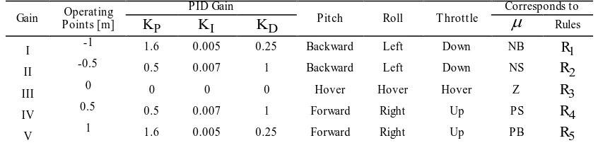
9. Tabulate the value of , and for each position representing the membership function The result of PID parameters gained by experimentally at each operating point can be tabulated in Table 2.
Table 2. The PID Parameters
Gain Points [m] Operating
PID Gain
Pitch Roll T hrottle
Corresponds to
P
K KI KD
RulesI -1 1.6 0.005 0.25 Backward Left Down NB R1
II -0.5 0.5 0.007 1 Backward Left Down NS R2
III 0 0 0 0 Hover Hover Hover Z R3
IV 0.5 0.5 0.007 1 Forward Right Up PS R4
V 1 1.6 0.005 0.25 Forward Right Up PB R5
For rules the function can be combined to get a function , as an output of the controller, as follows
(3)
3. RESULTS AND ANALYSIS
Fuzzy gain scheduling PID algorithm has been designed to be implemented on the AR.Drone 2.0 Elite Edition and tested indoor. The testing room size 6m x 6m x 4m with a floor made of striped line for the drone use its bottom camera to estimate and position in flight. While the position using ultrasonic sensors provided onboard the drone. To test the fuzzy gain scheduling PID algorithm, AR.Drone was flown point to point toward the x-axis from the initial coordinates [0,0,1] to the coordinates [1,0,1]. The same test is also done using PID controller algorithm.The response of AR.Drone will be compared with the test results using PID controller. The results of both are compared and shown in Figure 3. From the test results seen that AR.Drone with PID controller tend to experience overshoot approximately 20%. While AR.Drone with fuzzy gain scheduling PID gives better response with overshoot approximately 10% and settling time about 15 seconds. The next test, AR.Drone will be flown to several positions that form a grid on the coordinates
. The testing procedure is performed as follows:
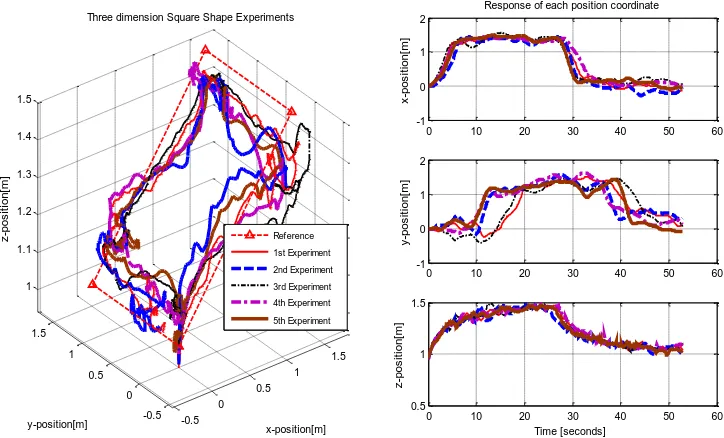
a. Enter the reference position that will be addressed by the drones on the front panel of the software that has been made. In this test, a reference that will be addressed is (1.5,0,1.5) then to (1.5,1.5,1.5), and to (0,1.5,1), finally back to the initial position (0,0,1).
Int J Elec & Comp Eng, Vol. 8, No. 4, August 2018: 1939 –1946
c. Switch ON auto, the AR.Drone will be autonomously flying toward predetermined reference. Change of set point is done if the position of the drone has been entered in error tolerances specified in the program,
d. Test is performed 5 times.
Figure 3. Comparison between PID response and Fuzzy Gain Scheduling PID response
The test result is shown in Figure 4. The picture on the left is the system response in 3 dimensions while the right image is the position response of each coordinate x, y, and z. The depiction of 3D showed that the AR.Drone can go to any desired reference point but it has a relatively large error in the position z. There are 2 of 5 times where the experiment yields a relatively good transient response. Experiments 1 and 3 were late when switching to get to the point (1.5, 1.5, 1.5). In general, each point can be ach ieved within a rise time of 10 seconds as seen in the left image.
Figure 4. Square shape experiments
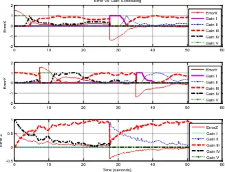
The gain scheduling process during the test is shown in Figure 5. It was taken from of one of the experiments above. It is seen that the journey start s from the initial X position error is 1.5 m so PID control
used Gain V, while the Y error is zero so the PID control used Gain III and errors Z 0.5 m, PID control used Gain IV. Along with drone journey towards a point of reference, the gain that works is the contribution of the two gain from appropriate membership function. Control signals, in this case, pitch, roll and throttle produced by fuzzy gain scheduling PID control is shown in Figure 6. In these control signals, there are restrictions on the control signal value ± 0.15 to avoid a collision with the wall due to the cramped indoor space.
Figure 5. Gain Scheduling Process
Figure 6. Control signal pitch, roll and throttle
Int J Elec & Comp Eng, Vol. 8, No. 4, August 2018: 1939 –1946 4. CONCLUS ION
This paper has implemented fuzzy gain scheduling PID contro l for position control of AR.Drone. The result of the test, which is to fly to the coordinates indicates that the PID gain switching process run in accordance with a predetermined operating point. AR.Drone can follow the references given well, b ut with a small error.
REFERENCES
[1] P.J. Bristeau, et al.,” The Navigation and Control Technology Inside the AR.Drone Micro UAV,” 18th IFAC Wor ld Congr ess, 2011.
[2] M . Mogenson,”The AR.Drone LabVIEW Toolkit: A Software Framework for the Control of Low Cost Quadrotor Aerial Robots,” Master of Science Thesis, Mechanical Engineer ing, TUFTS University, 2012
[3] A. Prayitno, V. Indrawati and G.Utomo,”Trajectory Tracking of AR.Drone Quadrotor Using Fuzzy Logic Controller,” Jour nal Telkomnika,vol.12 no.4, pp.819-828, Dec. 2014.
[4] V. Indrawati, A. Prayitno and T.A. Kusuma, “Waypoint Navigation of AR.Drone Quadrotor Using Fuzzy Logic Controller,” Jour nal Telkomnika,vol 13 no.3, pp.930-939, Sep. 2015.
[5] V. Indrawati, et al.,” Comparison of Two Fuzzy Logic Controller Schemes for Position Control of AR.Drone,”7th Inter national Confer ence on Infor mation Technology and Electr ical Engineer ing (ICITEE), 2015.
[6] A. Prayitno, et al.,”Comparison of PID and Fuzzy Controller for Position Control of AR.Drone,” IOP Conf. Ser ies: Mater ial Science and Engineer ing, vol.190, 2017.
[7] S.Y. Tang,” Vision-Based Control for Autonomous Quadrotor.” Final Repor t :Under gr aduated Senior Thesis, Depar tment of Mechanical and Aer ospace Engineer ing, Princeton University, 2013.
[8] R. Abbas and Q. Wu,” Improved Leader Follower Formation Control for Multiple Quadrotors Based AFSA,”
Jour nal Telkomnika, vol.13 no.1, pp.85-92, M ar. 2015.
[9] E.A. Seidabad, S.Vandaki and A.V. Kamyad,” Designing Fuzzy PID Controller for Quadrotor,” Inter national Jour nal of Advanced Resear ch in Computer Science & Technology (IJARCST), vol.2 no. 4, pp.221-227, 2014. [10] D. Gautam and C. Ha,” Control of a Quadrotor Using a Smart Self-Tuning Fuzzy PID Controller,” Inter national
Jour nal of AdVanced Robotic Systems, vol.10, pp.1-9, 2013
[11] M .H. Amoozgar, et al.,” Fault-Tolerant Fuzzy Gain-Scheduled PID for a Quadrotor Helicopter Testbed in the
Presence of Actuator Faults,” IFAC Confer ence on Advances in PID Contr ol, 2012.
[12] A. Prayitno, V. Indrawati and C. Arron,“ H-Infinity Control for Pitch-Roll AR.Drone,” Jour nal Telkomnika, vo.14 no.3, pp.963-973, 2016.
[13] A. Hazzabi, A. Laoufi, I.K. Bousserhane and M. Rahli,” Real Time Implementation of Fuzzy Gain Scheduling of PI Controller for Induction Machine Control,” Inter national Jour nal of Applied Engineer ing Resear ch., vol.1 no.1, pp.51-60, 2006.
[14] F.U. Syed, et al.,” Fuzzy Gain-Scheduling Proportional-Integral Control for Improving Engine Power and Speed