i
UNIVERSITI TEKNIKAL MALAYSIA MELAKA FACULTY OF ELECTRICAL ENGINEERING
FINAL YEAR PROJECT REPORT
DEVELOPMENT OF FIVE PHASE INDUCTION MOTOR SPEED USING FIELD ORIENTED CONTROL METHOD
NAME : AHMAD KHAIRI BIN ARIFFIN MATRIC NO. : B011210203
COURSE : 4BEKC
ii
DEVELOPMENT OF FIVE PHASE INDUCTION MOTOR SPEED USING FIELD ORIENTED CONTROL METHOD
AHMAD KHAIRI BIN ARIFFIN
A report submitted
in partial fulfillment of the requirements for the Bachelor in Electrical Engineering (Control, Instrumentation and Automation)
Faculty of Electrical Engineering
UNIVERSITI TEKNIKAL MALAYSIA MELAKA
iii
DECLARATION
I declare that this report entitle “Development of Five-phase Induction Motor Speed using Field Oriented Control Method” is the result of my own research except as cited in the references. The report has not been accepted for any degree and is not concurrently submitted in the candidature of any other degree.
Signature : ...
Name : AHMAD KHAIRI BIN ARIFFIN
iv
APPROVAL
I hereby declare that I have read through this report entitle “Development of Five-phase Induction Motor Speed using Field Oriented Control Method” and found that it has complied the partial fulfillment for awarding the Bachelor in Electrical Engineering (Control, Instrumentation and Automation)
Signature : ...
Supervisor‟s Name : EN. MOHAMED AZMI BIN SAID
v
ACKNOWLEDGEMENT
First of all, I would like to express my thankfulness and gratitude to Allah S.W.T who has given me all the strength that I needed to prepare this project report. With this opportunity, I would like to express my gratitude to the Faculty of Electrical Engineering (FKE), Universiti Teknikal Malaysia Melaka (UTeM) generally, and especially to my supervisor, Mr Mohamed Azmi bin Said for his help, advices and guidance that he gave during this project. Also to my parents, thanks to them because of their support to me with their prayer and their love. Last but not least, I would like to thank all my friends whom have been such wonderful friends to me and also to everyone who was involved in the completion of this project. I would like to thank them for all support and encouragement to me which have given me the courage and wisdom to fulfil my final year project.
vi
ABSTRACT
vii
TABLE OF CONTENT
CHAPTER TITLE PAGE
FRONT PAGE i
DECLARATION FORM iii
APPROVAL FORM iv
ACKNOWLEDGEMENT v
ABSTRACT vi
CONTENT vii
LIST OF FIGURES x
1 INTRODUCTION
1.1 Project Overview 1
1.2 Project Motivation 1
1.3 Problem Statement 2
1.4 Objectives 2
1.5 Scope of project 3
viii
2 LITERATURE REVIEW
2.1 Previous Work 4
2.2 Induction Motor 5
2.3 Multiphase Induction Motor 6
2.4 Voltage Source Inverter 8
2.5 Space Vector Modulation 9
2.6 Field Oriented Control 11
3 METHODOLOGY
3.1 Project Methodology 12
3.2 Project Flowchart 13
3.3 Field Oriented Control 14
3.4 Modeling Five-phase Voltage Source Inverter 16 3.5 Space Vector Modulation Scheme 18 3.6 Modeling of the drive system 43 3.7 Modeling of the Induction Motor 45 3.8 Field Oriented Control (FOC) 50
4 RESULT AND DISCUSSION
4.1 Five-phase Voltage Source Inverter 52 4.2 Space Vector Modulation (SVM) 56
ix
4.4 Experimental Part 64
5 CONCLUSION
5.1 Conclusion 66
5.2 Future Work 87
x
LIST OF FIGURE
NO TITLE PAGE
2.1 Induction Motor 6
2.2 Per-phase equivalent circuit for induction motor 7 2.3 Multiphase Induction motor circuit diagram 8
2.4 Voltage Source Inverter (VSI) 10
2.5 Phase to neutral voltage space vector on the dq plane 11
3.1 Flowchart of the development project 13
3.2 Field Oriented Control (FOC) 14
3.3 Five Phase Supply 15
3.4 Five-phase Voltage Source Inverter 17
3.5 General block diagram for Clarke transformation 18 3.6 Clarke transformation for five-phase supply 18 3.7 Waveform of five-phase supply for space vector modulation 19 3.8 Waveform of two phase voltage after transformation 20 3.9 General block diagram for separation of voltage 21
3.10 Separation into magnitude and angle 21
3.11 Waveform of voltage reference 22
3.12 Angle waveform 22
3.13 General block diagram for angle to sector 23
3.14 Angle to sector calculation block 23
3.15 Sector calculation based on the angle 24
xi
3.17 General block for generation of base time Ta and Tb 28
3.18 Generation of base time Ta and Tb 29
3.19 Waveform of base time Ta 30
3.20 Waveform of base time Tb 30
3.21 General block to generate four application times 31
3.22 Generation of four application time 31
3.23 Waveform of time that represent large vector, Tal 32 3.24 Waveform of time that represent large vector, Tbl 32 3.25 Waveform that represents time for medium vector, Tam 33 3.26 Waveform that represents time for medium vector, Tbm 33 3.27 Waveform that represents time for zero space vectors, To 34 3.28 General block diagram for generation of switching state for upper
part of inverter 35
3.29 Generation of switching state for upper part of the inverter 35
3.30 Waveform for switching pattern T1 37
3.31 Waveform for switching pattern T3 37
3.32 Waveform for switching pattern T5 38
3.33 Waveform for switching pattern T7 38
3.34 Waveform for switching pattern T9 39
3.35 Waveform for switching pattern T1, T3, T5, T7 and T9 39 3.36 General block diagram for generating the switching signal 40
3.37 Generating switching signal 41
xii
3.41 First block that produced flux 46
3.42 Mathematical block inside first block 47
3.43 Second block that produced current for stator and rotor 48
3.44 Mathematical block inside second block 48
3.45 Block that produced speed and torque 49
3.46 Components inside the last block 49
3.47 General block diagram of FOC 50
3.48 Arrangement of all blocks 51
4.1 Phase voltage for phase a of the voltage source inverter 45 4.2 Phase voltage for phase b of the voltage source inverter 46 4.3 Phase voltage for phase c of the voltage source inverter 47 4.4 Phase voltage for phase d of the voltage source inverter 48 4.5 Phase voltage for phase e of the voltage source inverter 48
4.6 Line voltage for leg A 49
4.7 Line voltage for leg B 50
4.8 Line voltage for leg C 51
4.9 Line voltage for leg D 51
4.10 Line voltage for leg E 51
xiii
4.4 Phase voltage for phase d of the voltage source inverter 53 4.5 Phase voltage for phase e of the voltage source inverter 53
4.6 Line voltage for leg A 54
4.7 Line voltage for leg B 54
4.8 Line voltage for leg C 55
4.9 Line voltage for leg D 55
4.10 Line voltage for leg E 55
4.11 Switching signal s1 56
4.12 Switching signal s2 56
4.13 Switching signal s3 57
4.14 Switching signal s4 57
4.15 Switching signal s5 57
4.16 Switching signal s6 58
4.17 Switching signal s7 58
4.18 Switching signal s8 58
4.19 Switching signal s9 59
4.20 Switching signal s10 59
4.21 Two-phase stator current 60
4.22 Stator current for phase a 61
4.23 Stator current for phase b 61
xiv
4.25 Stator current for phase d 62
4.26 Stator current for phase e 62
4.27 Torque of the motor 63
4.28 Speed of the induction motor 63
4.29 Gate driver 64
4.30 Setup of the hardware 64
1
CHAPTER 1
INTRODUCTION
1.1Project Overview
For this project, the speed of the motor has control by field oriented control (FOC) technique. The five-phase Voltage Source Inverter (VSI) is used to run five-phase induction motor. Space vector modulation (SVM) is chosen as the switching scheme due to its easiness in digital implementation. Space vector modulation gives effective control of multiphase VSI because of large numbers of space vectors. Voltage source inverter (VSI) implemented Insulated Gate Bipolar Transistor (IGBT). The speed of the motor should follow the reference speed that gives as input reference.
1.2Project Motivation
2
Five phase drives supplied from five-phase Voltage Source Inverter (VSI) and adequate method for VSI pulse width modulation are therefore required. For this project, space vector modulation schemes for a five-phase VSI generated to drive five phase induction motor and Field Oriented Method will be used to control the speed of the five phase induction motor.
1.3Problem Statement
From the previous project, the five phase induction motor simulation scheme was successfully created and was able to run with constant speed input. The speed of the five phase induction motor is yet to be controlled. To control the speed of the five phase induction motor, the control scheme to be designed.
1.4Objective
The research objectives are:
i. To control the speed of the five phase induction motor using field oriented method.
ii. To design the PID controller using voltage source inverter through space vector modulation scheme.
3
1.5Scope of Project
The scope of this project is running under the simulation using Matlab/Simulink and actual five phase induction motor control in a laboratory environment. Simulink software will be used for simulation of five phase motor drives purposes. The previous project was successfully create switching scheme for the five phase induction motor using Space Vector Modulation (SVM) method. So, for this project, the speed controller, which is Field Oriented Control (FOC) method will be added in order to control the speed of the five phase induction motor. After that, the controller will be simulated in Matlab/Simulink. Lastly, the control and inverter design will be tested in the laboratory using the actual five phase induction motor. The test will be conducted using the actual five phase induction motor, its drives and dspace controller, which is available in the research laboratory.
1.6Expected Project Outcome
The expected project outcome is the controller is able to control the speed of the five phase induction motor. Besides, able to modeling the simulation block diagram by using simulink for five phase induction motor, five phase inverter circuit and space vector modulation block diagram which is used for switching DC to multiphase AC. The purpose is to fed the induction motor. Other than that, designing PID controller and able to control the d-q components and also to control the speed of the motor. Next, able to model Clarke, park and ipark transformation which is to convert five-phase AC into dq component and from dq component back to five-pahse AC.
4
CHAPTER 2
LITERATURE REVIEW
2.1 Previous Work
Induction motor that consists of three phase surely known advantages of basic development, reliability, roughness, low maintenance and cost which has led to their far reaching use in numerous mechanical operations [7]. Nowadays, more published work has demonstrated that drives with more than three-phase have more advantages over ordinary three-phase such as lower torque and reduction in harmonic currents [7]. From the previous work, the speed response of the motor was controlled by using Space Vector Modulation (SVM). SVM was chose because of its easiness of digital implemetation. Besides, SVM gives better control of multiphase Voltage Source Inverter (VSI) because the numbers of space vector is large [8].
5
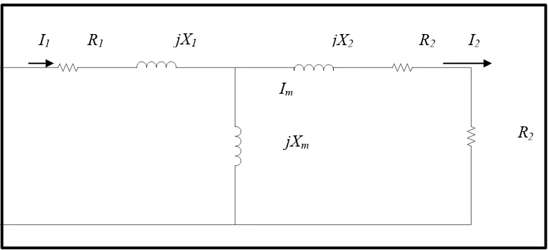
2.2 Induction Motor
The induction motor is the one of the most common electrical motor use. This motor runs at speeds lower than synchronous speed and it also known as a synchronous motor. The speed of rotation of the magnetic field in a rotating machine called as synchronous speed. Frequency and number of the machine influence synchronous speed of the motor. Flux generated in the rotor by the rotating magnetic field in the stator make the rotor to rotate.
There will be lag for the flux in the stator and rotor that makes the rotor cannot reach the synchronous speed. That's why the speed of the induction machine always less than synchronous speed. Induction process occurred in the induction motor.
6
Figure 2.1:Per phase equivalent circuit for induction motor.
2.3 Multiphase Induction Motor
Induction motor more than three-phase have same properties with three-phase induction motor that run without producing a twice line-frequency pulsating torque and accelerate theirs load from the rest. Multiphase induction motors not connected directly to three-phase supplies. Three-phase supply connected to the power electronic converter that drive excitation for the multiphase induction motor. The output of the converter must have the same phase with the stator winding of the motor.
Multiphase machine have some advantages compared to three-phase machine. One of the advantages of multiphase machine is the efficiency of the multiphase machine is higher than three-phase machine because of the multiphase machine produces a field with lower space-harmonic content at the stator excitation. Second, multiphase machine has greater fault tolerance than three-phase machine [1-2].
I1 R1 jX1 jX2 R2 I2
Im
9
2.5 Space Vector Modulation
Space vector modulation supplies AC machine with desired phase voltage. The space vector modulation method of generating the pulsed signals fit the requirement and minimizes the harmonic contents. Note that the harmonic content determines copper losses of the machine that account for a major portion of the machine losses [3].
Interest in multi phase drives has increased in recent years due to several advantages when compared to three-phase drives. The multiphase drive has some advantages that are less torque ripple, less acoustic noise and losses, reduced current per phase or increased reliability due to additional number of phases. Space vector modulation (SVM) is one of the most popular choices because it easy digital implementation and better utilization of the available DC bus voltage [4-5]
Power circuit topology for five-phase voltage source inverter with star-connected load presented. Five-phase space vector modulation can be developed as three phase space vector modulation for a period of the fundamental frequency. It shows the basic ten large and ten medium switching vectors for five-phase inverter.
10
When five-phase operated in PWM mode, there will be additional 22 switching states. 2n is the general equation for number of possible switching states, where n is the number of inverter leg. The remaining twenty-two switching states encompass three possible situations. First, all the states when four switches from upper (or lower) half and one from the lower (or upper) half of the inverter are „on‟ at state‟s 11 until 20. Next, two states when either all the five upper (lower) switches are „on‟ at state‟s 31 and 32. Last, the remaining states with three switches from the upper (lower) half and two switches from the lower (upper) half are „on‟ at state‟s 21until 30.
[image:24.612.144.526.84.431.2]� � � � � � � � � � � � � � � � � � � � � � � � � � � � � �