DOI: 10.12928/TELKOMNIKA.v13i2.1441 432
Stator Field-Orientation Speed Control for 3-Phase
Induction Motor Under Open-Phase Fault
Mohammad Jannati*1, Tole Sutikno2, Nik Rumzi Nik Idris1, Mohd Junaidi Abdul Aziz1 1
UTM-PROTON Future Drive Laboratory, Faculty of Electrical Engineering, Universiti Teknologi Malaysia, 81310 Skudai, Johor Bahru, Malaysia
2
Department of Electrical Engineering, Faculty of Industrial Technology, Universitas Ahmad Dahlan, Janturan, Umbulharjo 55164, Yogyakarta, Indonesia
*Corresponding author, e-mail: [email protected]
Abstract
The industrial requirements for the control of an induction motor (IM) under fault conditions continue to be of attention, as evidenced by the majority current publications. The focus is on developments of control methods which can be used for faulty IM. A novel vector control technique based on stator field-oriented control (SFOC) for a 3-phase IM under open-phase fault is proposed in this paper. MATLAB simulation results are presented to illustrate the improvement in performance of the proposed algorithm. It has shown that for providing an appropriate algorithm to control faulty machine with one opened phase, the modification in the conventional controller is possible.
Keywords: 3-Phase Induction Motor, Open- Phase Fault, Simulation Results, SFOC, Speed Control
1. Introduction
In some critical industrial applications such as aircraft and electric vehicle (EV). It is necessary to continue induction motor (IM) drive operation under fault conditions [1]. Generally, faults in IM drives can be classified as: fault in the inverter [2], fault in the sensors [1],[3] and fault in the electrical machine including stator and rotor faults [4]-[6].
Open-phase fault in stator windings of 3-phase IM is the most common type of faults in electric drives. This condition occurs because of the failure of one stator phase connection, inverter faults mitigated by using fuses [7],[8]. The conventional controller which is used for 3-phase IM drives cannot be able to work during fault conditions. If a conventional controller for healthy IM is applied to the faulty machine, oscillations in the motor torque and speed can be observed [9]-[11]. For this reason, an appropriate control algorithm is needed to control faulty machine.
In all pervious works, using transformation matrices, a modified control system for faulty machine has been presented. These transformation matrices, which are used to modify the FOC algorithm leads to system complexity. The main objective of this research is to expand stator field-oriented control (SFOC) technique for phase IM which can be also adopted for 3-phase IM under open-3-phase fault. Differently from the previous papers presented in [7]-[13], the proposed control drive system in this research do not used transformation matrices. This paper is organized as follows: In part 2, d-q model of faulty machine is shown. In part 3, the proposed idea for SFOC of faulty IM is presented. The MATLAB simulation results are shown in part 4 and part 5 concludes the paper.
2. Machine Model
s qr s dr s qs s ds r r r r q d r r r r r q r d q qs s d ds s s qs s ds i i i i dt d L r L dt d M M L dt d L r M dt d M dt d M dt d L r dt d M dt d L r v v
0 0 0 0 0 0 (1) s qr s dr s qs s ds r q r d q qs d ds s qr s dr s qs s ds i i i i L M L M M L M L 0 0 0 0 0 0 0 0
(2)
s
qr s ds d s dr s qs q
e
M
i
i
M
i
i
Pole
2
(3)
rr l e
F
dt
d
J
Pole
2
(4)where: ms q ms d ms ls qs ms ls
ds
L
L
L
L
L
M
L
M
L
L
2
3
,
2
3
,
2
1
,
2
3
(5)The superscript “s” in the variables of (1)-(4) indicates that the motor variables are in the stationary reference frame. Variables vsds, v
s qs, i
s ds, i
s qs, i
s dr, i
s qr, λ
s ds, λ
s qs, λ
s dr and λ
s
qr are the d-q
axes voltages, currents, and fluxes of the stator and rotor. rs and rr denote the stator and rotor
resistances. Md, Mq and Lr denote the stator, the rotor self and mutual inductances. rs and rr are
stator and rotor resistance. r is the motor speed. τe, τl, J and F are electromagnetic torque, load
torque, inertia and viscous friction coefficient. Re-writing the model (1)-(4) by removing some asymmetries is useful for vector control applications. A transformation matrix for the stator variables is defined as:
3 0 0 1 0 0 1 q d M M
T (6)
This should be applied as follows:
After the simplification, the new mathematical model of 3-phase IM under open-phase fault is:
s qr s dr s qs s ds s s qr s dr s qs s ds r r s qr s dr s qs s ds s qr s dr s qs s ds r r s s s qs s dsi
i
i
i
r
dt
d
i
i
i
i
r
r
r
r
v
v
1 1 1 1 1 1 1 1 1 10
0
0
0
0
0
0
0
0
0
2
0
0
0
0
0
0
0
0
0
0
0
0
0
0
0
0
0
0
0
0
0
0
0
0
0
0
0
0
0
0
0
0
0
(8)
s qr s dr s qs s ds s s qr s dr s qs s ds r r s qr s dr s qs s ds s qr s dr s qs s ds r r s s s qs s dsi
i
i
i
r
dt
d
i
i
i
i
r
r
r
r
v
v
1 1 1 1 1 1 1 1 1 10
0
0
0
0
0
0
0
0
0
2
0
0
0
0
0
0
0
0
0
0
0
0
0
0
0
0
0
0
0
0
0
0
0
0
0
0
0
0
0
0
0
0
0
(9)
s qr s dr s qs s ds ds qs s qr s dr s qs s ds r d r d d ds d ds s qr s dr s qs s dsi
i
i
i
L
L
i
i
i
i
L
M
L
M
M
L
M
L
1 1 1 1 1 10
0
0
0
0
0
0
0
0
0
3
0
0
0
0
0
0
0
0
0
0
0
0
0
(10)
s
qr s ds d s dr s qs d
e
M
i
i
M
i
i
Pole
1 12
(11)
rr l e
F
dt
d
J
Pole
2
(12)The term (3Lqs-Lds) in equation (11) is almost zero (3Lqs-Lds=3Lls+1.5Lms-Lls
-1.5Lms=2Lls≈0) and consequently, equation (11) will provide balanced stator fluxes. With respect
to (10) it must be noted that besides the influence of stator flux, vds1 and vqs1 are unbalanced
due to 2rs. The influence of 2rs cannot be ignored at medium or low speed. Note that, differently
from the faulty model given by (1)-(5), equations (8)-(12) are useful in deriving the vector control approaches, as shown in section 3.
3. Stator-Flux Control
Calculation of machine torque as a function of stator currents and stator fluxes can be achieved by using (10) and (11), and it can be written as follows:
qs dss qs s ds s ds s qs
e
L
L
Pole
i
i
Pole
3
2
2
1 1 1 1 (13)By neglecting ∆τ as mentioned before the form of equation (13) becomes like balanced 3-phase IM torque equation. It is concluded in the faulty mode, the balanced stator currents generate unbalanced stator fluxes. If (3Lqs-Lds)=0, then the stator fluxes become balanced and
oscillating term (∆τ) in the faulty machine torque will be removed. Therefore, it is possible to apply the FOC principles to control the stator flux of the 3-phase IM under open-phase fault.
indicates that the variables are in the synchronous reference frame). Based on this assumption, the SFOC equations for faulty 3-phase IM can be represented as (14)-(16) [15],[16].
st qs
r str ds r st ds
r r ds
s
i
dt
d
T
L
T
i
dt
d
T
dt
d
T
L
1 11
1
1
1
(14)
st qs st ds ds s
r
r ds r st
str
i
i
L
dt
d
T
T
L
1 1 1
1
(15)
st qs s
e
i
Pole
1 1
2
(16)
in which,
r r r r ds
d
r
L
T
L
L
M
1
,
2
(17)3.1. Direct Stator Field-Oriented Control
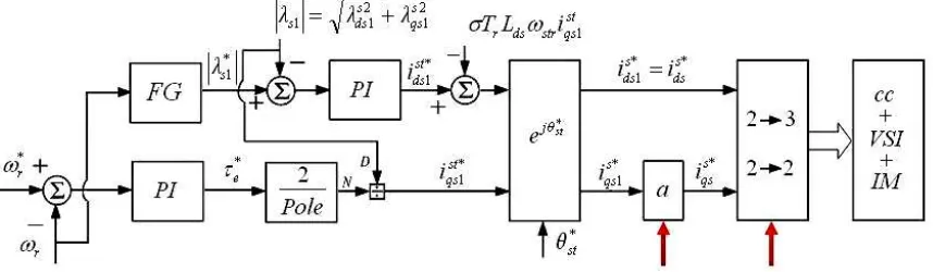
Based on the vector model given by (14)-(17), Figure 1 can be proposed for direct stator field-oriented control of both healthy and faulty 3-phase IM. In Figure 1, the red arrows show the parts of the conventional vector controller that require to be modified for controlling faulty machine as shown in Table 1.
Figure 1. Block diagram of the proposed DSFOC for vector control of healthy and faulty 3-phase IM
In Figure 1, |λs1*| and τe* represent the desired amplitude of the stator flux and
electromagnetic torque, respectively. The block ejθst*, transfer motor variables from coordinate reference frame aligned along with the stator flux vector to the stationary reference frame. Furthermore, idss* and iqss*represent the reference d and q currents supplied to the stator current
Table 1. Comparison between two vector control techniques
a 2→3 and 2→2 based on [9] and [16]
Healthy IM
a
1
cs bs as cs bs as s s qs s dsi
i
i
i
i
i
T
i
i
2
3
2
3
0
2
1
2
1
1
3
2
* *Faulty IM
a
3
bs as bs as s s qs s dsi
i
i
i
T
i
i
1
1
1
1
2
2
* *Moreover, the angle of the reference frame (θst*) is given by:
s ds s qs st 1 1 1 *tan
(18)where,
s ds s s ds sds1
v
r
i
(19)
s qs s s qs sqs1
v
r
i
(20)3.2. Indirect Stator Field-Oriented Control
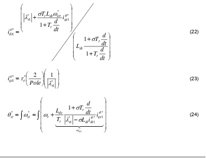
Based on the vector control model for healthy 3-phase IM (equations (14)-(17)), the stator d and q axis currents and electromagnetic torque of machine can be written as following equations:
dt
d
T
dt
d
T
L
i
dt
d
T
L
T
i
r r ds st qs r str ds r s st ds1
1
1
* 1 * * 1 * 1
(22)
* 1 * * 11
2
s e st qsPole
i
(23)
* * 1 * 1 * 1 * *1
str st qs st ds ds s r r ds r st sti
i
L
dt
d
T
T
L
Using these equations, Figure 2 can be proposed for indirect stator field-oriented control of both healthy and faulty 3-phase IM.
Figure 2. Block diagram of the proposed ISFOC for vector control of healthy and faulty 3-phase IM
4. Simulation Results
Two control strategies for healthy and faulty 3-phase IM was studied by simulations (MATLAB software). Selected results are shown in Figure 3 and Figure 4. In both cases, the 3-phase IM started in the healthy condition and without load, and then at t=0.5s a step load equal to 0.5N.m is applied. After that, at t=1s, a phase cut-off fault is happened in phase “c”. After that at t=3s the value of load is changed to 2N.m. In Figure 3, a conventional control system for healthy and faulty 3-phase IM has been simulated. In Figure 4, the proposed control system based on Figure 2 for healthy and faulty 3-phase IM has been simulated. These results were obtained with a machine fed by PWM-VSI. In this paper, very fast fault detection is assumed as considered in [17]. In the simulations, the reference for the motor speed and stator flux is considered 400rpm and 1wb respectively. The simulated 3-phase IM parameters are listed in Table 2.
Table 2. Simulated 3-phase IM parameters
Parameters Values Voltage 125V Power 475W
f 50HZ
Pole 4
rs 20.6Ω
Rr 19.15Ω
Lls=Llr 0.0814H
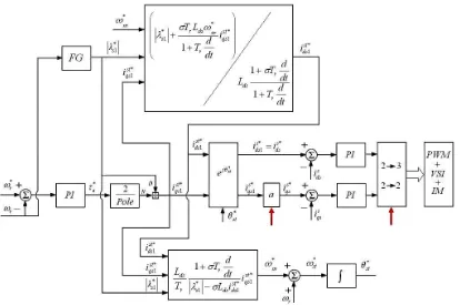
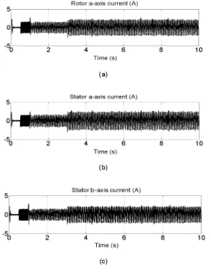
As shown in Figure 3 and Figure 4, in the healthy situation, both conventional and proposed controller show good tracking performance and fast response. Simulation results of Figure 3 show that the real IM speed cannot follow the reference speed properly in the faulty mode (see Figure 3 (e)). In this case and after open-phase fault, the electromagnetic torque waveforms have many oscillations. As shown in Figure 3 (d), using conventional controller the oscillations of electromagnetic torque in the faulty condition is about 1N.m.
(a)
(b)
(c)
(e)
Figure 3. Simulation results of the conventional ISFOC for vector control of healthy and faulty 3-phase IM, (a) Rotor a-axis current (b) Stator a-axis current, (c) Stator b-axis current, (d) Torque,
(e) Speed
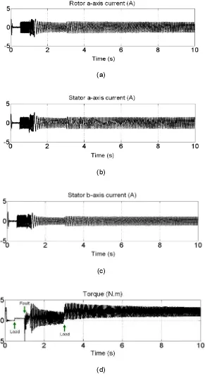
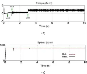
Simulation results of Figure 4 demonstrate that using proposed drive system, the real IM speed can track the reference speed even under fault and under load. In Figure 4, the stator and rotor currents waveform show that the machine currents are nearly sinusoidal in both healthy and faulty conditions. Furthermore, using proposed controller, the electromagnetic torque waveforms contain low oscillations even in the faulty mode.
(a)
(b)
(d)
(e)
Figure 4. Simulation results of the proposed ISFOC for vector control of healthy and faulty 3-phase IM, (a) Rotor a-axis current (b) Stator a-axis current, (c) Stator b-axis current, (d) Torque,
(e) Speed
In this case as shown in Figure 4 (d), using proposed controller the oscillations of electromagnetic torque in the healthy condition is about 0.02N.m and in the faulty condition and is about 0.3N.m. It is shown that the proposed ISFOC controller for vector control of healthy and faulty machine has a good speed control and sufficient vector control characteristics.
5. Conclusion
This research has discussed two vector control strategies based on SFOC for 3-phase IM drive systems under open-phase fault (Direct SFOC and Indirect SFOC). It was shown using a few modifications in the conventional controller for healthy machine vector control of 3-phase IM with one opened phase is possible. Simulation results were considered acceptable and have confirmed the claimed features. In perspective, the method presented here can also be extended to control single-phase IM drives with two main and auxiliary windings.
References
[1] Meh B, D Diallo, M Zeraoulia. Advanced fault-tolerant control of induction-motor drives for EV/HEV traction applications: From conventional to modern and intelligent control techniques. IEEE Transactions on Vehicular Technology. 2007; 56(2): 519-528.
[2] F Meinguet, P Sandulescu, X Kestelyn, E Semail. A method for fault detection and isolation based on the processing of multiple diagnostic indices: application to inverter faults in AC drives. IEEE Transactions on Vehicular Technology. 2013; 62(3): 995-1009.
[3] A Raisemche, M Boukhnifer, C Larouci, D. Diallo. Two Active Fault Tolerant Control Schemes of Induction Motor Drive in EV or HEV. IEEE Transactions on Vehicular Technology. 2014; 63(1): 19-29. [4] GM Joksimovic, J Penman. The detection of inter-turn short circuits in the stator windings of
operating motors. IEEE Transactions on Industrial Electronics. 2000; 47(5): 1078-1084.
[5] A Sayed-Ahmed, NA Demerdash. Fault-tolerant operation of delta-connected scalar-and vector-controlled AC motor drives. IEEE Transactions on Power Electronics. 2012; 27(6): 3041-3049. [6] J Faiz, V Ghorbanian, B Ebrahimi. EMD-Based Analysis of Industrial Induction Motors with Broken
[7] Z Yifan, TA Lipo. An approach to modeling and field-oriented control of a three phase induction machine with structural imbalance. In Proc. APEC, San Jose, TX. 1996: 380-386.
[8] Y Zhao, TA Lipo. Modeling and control of a multi-phase induction machine with structural unbalance.
IEEE Transactions on Energy Conversion. 1996; 11(3): 570-577.
[9] M Jannati, A Monadi, NRN Idris, MJA Aziz. Speed Sensorless Vector Control of Unbalanced Three-Phase Induction Motor with Adaptive Sliding Mode Control. International Journal of Power Electronics and Drive Systems (IJPEDS). 2014; 4(3): 406-418.
[10] M Jannati, SA Anbaran, MI Alsofyani, NRN Idris, MJA Aziz. Modeling and RFOC of faulty three-phase IM using Extended Kalman Filter for rotor speed estimation. In 8th International Power Engineering and Optimization Conference (PEOCO). 2014: 270-275.
[11] M Jannati, A Monadi, GW Yen, SH Asgari, NRN Idris, MJA Aziz. A simple vector control technique for 3-phase induction motor under open-phase fault based on GA for tuning of speed PI controller. In 2014 IEEE Conference on Energy Conversion (CENCON). 2014: 213-218.
[12] M Jannati, NRN Idris, MJA Aziz, A Monadi, AAM Faudzi. A Novel Scheme for Reduction of Torque and Speed Ripple in Rotor Field Oriented Control of Single Phase Induction Motor Based on Rotational Transformations. Research Journal of Applied Sciences, Engineering and Technology. 2014; 7(16): 3405-3409.
[13] M Jannati, SH Asgari, NRN Idris, MJA Aziz. Speed Sensorless Direct Rotor Field-Oriented Control of Single-Phase Induction Motor Using Extended Kalman Filter. International Journal of Power Electronics and Drive Systems (IJPEDS). 2014; 4(4): 430-438.
[14] PC Krause. Analysis of Electric Machinery. McGraw-Hill. 1986.
[15] M Boussak, K Jarray. A high-performance sensorless indirect stator flux orientation control of induction motor drive. IEEE Transactions on Industrial Electronics. 2006; 53(1): 41-49.
[16] P Vas. Sensorless vector and direct torque control. Oxford University Press. 1998.
[17] A Gaeta, G Scelba, A Consoli. Modeling and control of three-phase PMSMs under open-phase fault.