ISSN: 1992-8645 www.jatit.org E-ISSN: 1817-3195
FUZZY OPTIMIZATION FOR SPEED CONTROLLER OF AN
INDIRECT VECTOR CONTROLLED INDUCTION MOTOR
DRIVE USING MATLAB SIMULINK
1ANGGUN ANUGRAH, 2ROSLI OMAR, 3MARIZAN SULAIMAN,4AZHAR AHMAD
Faculty of Electrical Engineering, Universiti Teknikal Malaysia, Melaka, Malaysia
E-mail: [email protected]
ABSTRACT
The aim of this paper is to investigate the performance of a Fuzzy-Logic-Controller (FLC) which is applied on three-phase induction motor drive system for high-performance industrial applications. In this paper, the FLC is used as a speed controller to replace the conventional PI speed controller. The FLC will determine the time of switching on the Space Vector Pulse Width Modulation (SVPWM) inverter that supplies power to drive the induction motor considering variable direct and quadrature axis inductances. The performance of the suggested technique has been simulated and developed using MATLAB/ SIMULINK for dynamic operating condition, such as certain change in command speed, and step change in load. The simulation result shows the feasibility of the proposed technique in order to improve the speed response and low torque ripple on three phase induction motor drive.
Keywords: Field Oriented Control, Fuzzy Logic Controller, Space Vector PWM, Induction motor
1.
INTRODUCTIONAmong various ac motors, induction motor (IM) occupies almost 90% of the industrial drives due to its simple and robust construction; however, the control of IM is complex due to its nonlinear nature and the parameters change with operating conditions. Artificial intelligent controller (AIC) could be the best candidate for IM control. Over the last two decades researchers have been working to apply AIC for induction motor drives [1-6]. This is because that AIC possesses advantages as compared to the conventional PI, PID and their adaptive versions.
Mostly, it is often difficult to develop an accurate system mathematical model since the unknown and unavoidable parameter variations, and unknown load variation due to disturbances, saturation and variation temperature. In this paper a fuzzy logic controller (FLC), as an AIC, is considered for motor control purpose [7-10]. The main advantages are that the designs of these controllers do not depend on accurate system mathematical model and their performances are robust.
The performance of the proposed drive is investigated in simulation. In order to prove the superiority of the proposed FLC, the performances of the proposed controller are also compared to those obtained by a conventional PI controller.
2.
INDUCTION MOTOR MODELThe dynamic space vector model of IM in an arbitrary frame is expressed as
= + p + j (1)
= + p + j (2)
= + (3)
= + (4)
= ⊗ = (5)
ISSN: 1992-8645 www.jatit.org E-ISSN: 1817-3195
= + σ p + (σ + ) (7)
= (8)
= − = (9)
= (10)
Where rotor flux is only decided by the d-axis current, and if rotor flux is constant, the electromagnetic torque is proportional to the q-axis current, thus rotor flux and electromagnetic torque is decoupled, which provides convenience for control.
In conventional RFOC, PI is used to regulate the d-axis and q-axis current in synchronous frame and the control law is
* = ( + )( * ) (11)
* = ( + )( * ) (12)
3.
PRINCIPLE OF FLCThe mathematical tool for the FLC is the Fuzzy set theory introduced by Zadeh [11], which incorporates human experience in the controller. A typical FLC block diagram is illustrated in Fig. 1.
The range of input and output variables after scaling is between -5 and +5. Fig.2 and Fig. 3 show the fuzzy sets and corresponding triangular membership function description of each signal. The fuzzy sets are defined from big to small as follows: PVB, PB, PM, PS, Z, NS, NM, NB, NVB.
The membership function of input and output are shown in Fig. 2 and Fig. 3 respectively. Tab. I shows the inference rule used in this paper, which is the key part of FLC. By well designing the inference rule, excellent performance can be achieved. The mapping relationship between input variables and output variable is illustrated in Fig. 4.
ISSN: 1992-8645 www.jatit.org E-ISSN: 1817-3195
The input of FLC for speed control is the error between commanding speed value and real speed value, and its output is q-axis torque current. The input of FLC for flux control is the error between commanding flux value and real flux value, and its output is d-axis magnetizing current.
4.
DESIGN SYSTEM CONTROLTheoritically, the field oriented control for the Induction motor drive can be manly categorized into two types; indirect and direct schemes. The field to be oriented could be rotor, stator, or air gap flux linkage. In the indirect filed oriented control, the slip estimation with measured or estimated rotor speed is required in order to compute the synchronous speed. There is no flux estimation appearing in the system. For the direct scheme, the synchronous speed is computed basing on the flux-
angle which is available from flux estimator or flux sensor (e.g., Hall effect).
In this implementing system, the indirect flux oriented control system with measured speed based on capture is chosen. The overal block diagram can be depicted in figure 5.
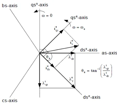
The fundamental of field oriented control (or flux vector control) for the AC motors, such as induction or synchronous motors, is to align the total flux into the synchronously rotating d-axis.
With the important result of this alignment, the electromagnetic torque and flux produced by motor can be independently controlled by the d-axis and q-axis stator current in the synchronously rotating reference frame, respectively. Figure 6 shows the
Fig. 5. Blok diagram of Indirect Field Oriented Control.
ISSN: 1992-8645 www.jatit.org E-ISSN: 1817-3195
5.
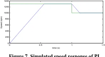
SIMULATION RESULTFig. 7 shows the simulated speed response of rotor using conventional technique PI. The green line color shows the speed reference at starting 1300 rpm, then after 1 second command speed was given to reduce the speed at 1000 rpm while the blue line color shows the speed actual motor.
0 0.5 1 1.5
Figure 7. Simulated speed response of PI
Next, Fig. 8 shows torque response of motor in conventional technique PI, then Fig.9 show stator
Figure 8. Simulated torque response of motor in conventional technique PI
Figure 9. Simulated stator currents transient response of motor in conventional technique PI
In Fig. 10 shows simulated speed response of rotor in FLC technique and below are respectively torque response in FLC, Fig .11. Then Fig. 12 shows stator currents transient in FLC.
Figure 10. Simulated speed response using FLC technique
Figure 8. Simulated torque response of motor using FLC technique
Figure 9. Simulated stators current transient response of motor using FLC technique
6.
CONCLUSIONISSN: 1992-8645 www.jatit.org E-ISSN: 1817-3195
The ripple torque is also can be reduced through this method. In the future work the prototype will be developed in order to verify simulation and experimental results. The suggested algorithm will be implemented in experimental to drive three direct and quadrature axis inductances”.
Computer and information technology, 2007. iccit 2007. 10th international conference on. [2] Iqbal, J. and C. Bhurtun (2005). “Fuzzy logic
based speed control and slip compensation for rotor time constant variations in a field-oriented induction motor drive”.
Computational Cybernetics, 2005. ICCC 2005. IEEE 3rd International Conference on. [3] Karanayil, B., M. F. Rahman, et al. (2005).
"Stator and rotor resistance observers for
induction motor drive using fuzzy logic and artificial neural networks". Energy Conversion, IEEE Transactions on 20(4): 771-780.
[4] Kumar, R., R. A. Gupta, et al. (2007). “Indirect vector controlled induction motor
drive with fuzzy logic based intelligent controller”. Information and Communication
Technology in Electrical Sciences (ICTES 2007), 2007. ICTES. IET-UK International Conference on.
[5] Mariun, N., S. B. M. Noor, et al. (2004). “A
fuzzy logic based controller for an indirect vector controlled three-phase induction motor”. TENCON 2004. 2004 IEEE Region
10 Conference.
[6] Miloud, Y. and A. Draou (2002). “Fuzzy logic
based rotor resistance estimator of an indirect vector controlled induction motor drive”.
IECON 02 [28th Annual Conference of the Industrial Electronics Society, IEEE 2002]. [7] Minh, T.-C., J. L. S. Neto, et al. (1996).
“Fuzzy logic based controller for induction
motor drives”. Electrical and Computer
Engineering, 1996. Canadian Conference on.
[9] Rathore, A. K. (2004). “Improved
performance of fuzzy logic based direct field oriented controlled induction motor”. Power
Electronics Congress, 2004. CIEP 2004. 9th IEEE International.
[10] Uddin, M. N. and W. Hao (2007). "Development of a Self-Tuned Neuro-Fuzzy
Controller for Induction Motor Drives."
Industry Applications, IEEE Transactions on 43(4): 1108-1116.
[11] L.A. Zadeh, “Fuzzy sets”, inform. Control, vol8, pp.338-353, 1965.
[12] Uddin, M. N., T. S. Radwan, et al. (2002). "Performances of fuzzy-logic-based indirect
vector control for induction motor drive".
Industry Applications, IEEE Transactions on 38(5): 1219-1225.
[13] Uddin, M. N. and H. Wen (2004). “Development of a self-tuned neuro-fuzzy
controller for induction motor drives”.
Industry Applications Conference, 2004. 39th IAS Annual Meeting. Conference Record of the 2004 IEEE.
[14] Woo-Yong, H., K. Sang-Min, et al. (2003). “Sensorless vector control of induction motor
using improved self-tuning fuzzy PID controller”. SICE 2003 Annual Conference.
[15] Wu, A. I. and P. K. S. Tam (1999). “An
adaptive speed control for induction motor drive using fuzzy neural network based on fuzzy hierarchy error approach”. Electric
Machines and Drives, 1999. International Conference IEMD '99.
[16] Xianglong, J., Z. Jin, et al. (2003). “Neural
network speed controller of induction motor drive based on direct MRAC method”.
Industrial Electronics Society, 2003. IECON '03. The 29th Annual Conference of the IEEE. [17] Zongkai, S., Z. Yuedong, et al. (2009). “Fuzzy
neural network-based model reference adaptive inverse control for induction machines”. Applied Superconductivity and
ISSN: 1992-8645 www.jatit.org E-ISSN: 1817-3195
AUTHOR PROFILES:
Anggun Anugerah, ST received his the degree in electrical engineering from Andalas University Indonesia . Where he is currently working toward the Msc degree. His research interest include power electronic,electrical drive and power quality.
Rosli Omar received the degree in electrical &
electronics engineering from University
Technology Malaysia and M.Eng from University Of Science Malaysia. Currently he is a senior lecturer of Faculty of Electrical, University Technical Malaysia Malacca. His research interests include power electronic,power quality and renewable energy.
Prof Dr Marizan Sulaiman obtained his B.sc., M.E.E. and Ph.D. in Electrical from University Of Missouri-Columbia (UMC), USA . Currently he is the Dean of Faculty of Electrical, University Technical Malaysia Malacca. His research interests including all area of power systems, energy efficient systems, control and instrumentation and e-learning.