DOI: 10.12928/TELKOMNIKA.v15i1.3568 254
Mathematical Modeling and Fuzzy Adaptive PID Control
of Erection Mechanism
Feng Jiangtao*, Gao Qinhe, Guan Wenliang
Xi’an High-tech Research Institute, Tongxin Road No. 2, Hongqing Town, Baqiao District, Xi’an, Shaanxi, China
*Corresponding author, e-mail: [email protected]
Abstract
This paper describes an application of fuzzy adaptive PID controller to erection mechanism. Mathematical model of erection mechanism is derived. Erection mechanism is driven by electro-hydraulic actuator system which is difficult to control due to its nonlinearity and complexity. Therefore fuzzy adaptive PID controller is applied to control the system. Simulation was performed in Simulink software and experiment was accomplished on laboratory equipment. Simulation and experiment results of erection angle controlled by fuzzy logic, PID and fuzzy adaptive PID controllers were respectively obtained. The results show that fuzzy adaptive PID controller can effectively achieve the best performance for erection mechanism in comparison with fuzzy logic and PID controllers.
Keywords: erection mechanism, electro-hydraulic system, fuzzy logic control, PID control
Copyright © 2017 Universitas Ahmad Dahlan. All rights reserved.
1. Introduction
Erection mechanism of large machineries and armaments is a complex mechanical, electronic and hydraulic integration system. It can be mainly divided into electro-hydraulic part and mechanical part. Electro-hydraulic actuator has become one of the most important actuators in the past decade. The main reasons why hydraulics is preferred to mechanical drives in industrial applications include their ability to produce large forces at high speeds, high power density and good dynamic performance [1]. Its application can be found in many engineering fields such as automotive industries, machine tools, aircrafts and manufacturing equipment [2-4].
the traditional PID control and fuzzy control has been applied to solve many engineering problems [12].
This paper is organized as follows. Mathematical model of the electro-hydraulic system is derived. Kinetic analysis of erection mechanism is accomplished. The relationships of erection force, erection angle and the length of hydraulic cylinder are obtained. Fuzzy adaptive PID controller is designed in combination of fuzzy logic and PID control method. Models of erection system and fuzzy adaptive controller are established in Simulink. Experimental studies are completed on laboratory equipment. The aim of this research is to investigate the effect of fuzzy adaptive PID controller on erection mechanism.
2. Mathematical Modeling of Erection System 2.1. Model of the Electro-Hydraulic System
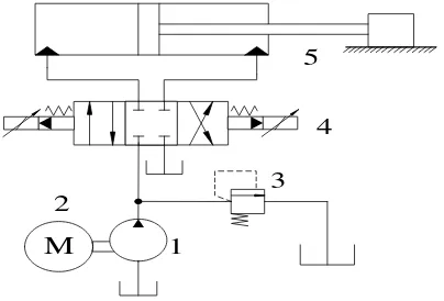
Erection mechanism is mainly composed of hydraulic system and mechanical system. Mathematical models of each system are established separately. Hydraulic system includes hydraulic pump, relief valve, hydraulic cylinder and electro-hydraulic proportional valve, as is shown in Figure 1.
Figure 1. Hydraulic Principle of Erection System
The pump model can be built by the following equation.
p p p v
Q D w (1)
Where Dp is pump displacement. wp is rotational speed of the motor. v is volumetric efficiency.
The model of the electro-hydraulic proportional directional valve is expressed by the following formulas.
1 1
2( s )
d x
p p q C A
(2)
2 2
2
d y
p q C A
(3)
Where q1 and q2 are fluid flows from and to cylinder. ps is the hydraulic supply pressure. Axand Ay are the spool valve areas. Cd is the discharge coefficient. ρ is the fluid density.
The hydraulic cylinder model is built using the cavity node method. The dynamic equation of the hydraulic cylinder is described by the second Newton’s Law.
01 1 1
1 1 ( ec ic) 1 ic 2
e
V A y dp dy
q A C C p C p
dt dt
˄ ˅ (4)
5
M
1
4
02 2 2
Where A1 is cross-sectional area of the piston and A2 is the annular area of piston rod chamber. y is the piston displacement. V01 and V02 are the initial volumes of the two cylinder chambers. A1y and A2y represent the flow rates as a function of volume change due to the piston motion.
βe is the fluid bulk modulus. p1 and p2 are the pressures in the forward and return cylinder chambers.Cic and Cec are the internal and external leakage coefficients. m is mass of the load. F is the external force.
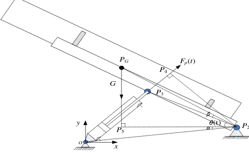
2.2. Kinetic Analysis of Erection Mechanism
Mechanical part of erection mechanism is shown in Figure 2. The load revolves around the point P2 driven by erection cylinder.
Figure 2. Kinetic Model of Erection Mechanism
We can obtain the following equation through Euler dynamic equations in coordinate
thrust force of erection cylinder. G is gravity of the load.
Geometry relationships are described by the following equations.
2 3
The relationship of erection angle and cylinder length can be acquired by using cosine
3. Fuzzy Adaptive PID Controller Design
We adopt fuzzy adaptive PID control method in erection process to enhance control performance. PID control is connected with fuzzy control and then the parameters of PID control method can change based on circumstance [13]. Fuzzy adaptive PID control method can make
full use of operators’ successful nonlinear experience and excellent effect of PID control. It can
improve precision and achieve better effect compared with PID control and fuzzy control. The differential equation of PID control is as follows [14].
coefficient. TI is integral time constant. TD is differential time constant.
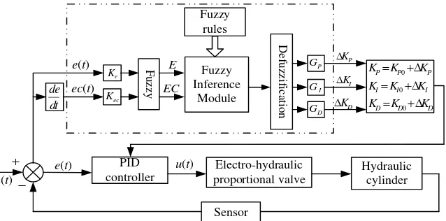
The structure of fuzzy adaptive PID controller is shown in Figure 3. Fuzzy logic controller is used to change the parameters of PID controller. Its input variables are error e(t) and error change rate c(t) and output variables are △KP, △KI, △KD, which are respectively added
to initial values KP0, KI0 and KD0.
Figure 3. The Structure of Fuzzy Adaptive PID Controller
Figure 4. Membership Function Cure of Input
All of the variables are implied as linguistic values and defined with seven linguistic
the system response and reduce time constant with damping coefficient. KDshould be adopted
relatively small value to avoid out of range control at the beginning. To avoid large overshoot, remove the integral action.
2. When e(t) is medium, KP should be adopted relatively small value to minimize
response overshoot. The value of KD is important and should be adopted medium value. The
value of KI should be appropriately increased.
3. When e(t) is relatively small, KP and KI should be adopted relatively large value to
have good steady state and avoid oscillation at equilibrium point. The value of KD should be
appropriate.
Based on the above relationships and the impact of c(t), fuzzy control rules are obtained in Table 1 through theoretical analysis.
Table 1. Fuzzy Control Rules
△KP /△KI /△KD
e
NB NM NS ZO PS PM PB
c
NB PB/NB/NS PB/NB/PS PM/NM/PB PM/NM/PB PS/NS/PB ZO/ZO/PM ZO/ZO/NS
NM PB/NB/NS PB/NB/PS PM/NM/PB PS/NS/PM PS/NS/PM ZO/ZO/PS NS/ZO/ZO
NS PM/NB/ZO PM/NM/PS PM/NS/PM PS/NS/PM ZO/ZO/PS NS/PS/PS NS/PS/ZO
ZO PM/NM/ZO PM/NM/PS PS/NS/PS ZO/ZO/PS NS/PS/PS NM/PM/PS NM/PM/ZO
PS PS/NM/ZO PS/NS/ZO ZO/ZO/ZO NS/PS/ZO NS/PS/ZO NM/PM/ZO NM/PB/ZO
PM PS/ZO/NB ZO/ZO/PS NS/PS/NS NM/PS/NS NM/PM/NS NM/PB/NS NB/PB/NB
PB ZO/ZO/NB ZO/ZO/NM NM/PS/NM NM/PM/NM NM/PM/NS NB/PB/NS NB/PB/NB
Take the first rule as an example, the above rule can be interpreted as “if e is NB and c is NB, then △KP /△KI /△KD are PB/NB/NS”. Mamdani algorithm is introduced as fuzzy implication
relation [18].
( , ) ( )( , )
= min( ( ), ( )) ( ) ( )
R a u A U a u
A a U u A a U u
(12)
Triangular shape function is chosen as output membership function which is shown in Figure 5 [19].
Figure 5. Membership Function Cure of Output
Centroid is chosen as defuzzification method [20], which calculates the area center of the fuzzy set membership function curve surrounded by the horizontal coordinate. The horizontal coordinate value of the center is chosen as the representative value of the fuzzy set. The membership function of F set is A(u) on the domain U and the horizontal coordinate u0 corresponding to the area center is calculated by the following formula [21].
0
( )
( ) U
U
A u udu u
A u du
(13)ZO PS PM PB
1.0 NS NM NB
0 2 4 6
-2 -4
4. Simulation and Results
4.1. Modeling Erection Mechanism in Simulink
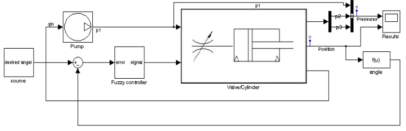
Figure 6 illustrates the top level Simulink diagram of the entire system. The pump flow and the desired angle signal are simulation inputs. The pressure and cylinder position are
simulation outputs. The model is organized as several subsystems blocks such as the ‘source’
model, the ‘pump’ model, the ‘valve/cylinder’ model and the ‘fuzzy adaptive PID controller’
model. The output of the controller is derived to control motion of the valve spool. Position of the spool influences the nominal flow into cylinder chamber. The nominal flow change will change the volume and pressure inside both cylinder chambers. Finally, the piston position is affected, therefore the mechanical mechanism moves driven by cylinder piston. Hence, the performance of the system is dependent on the output of the controller.
Figure 6. Simulink Block of the Complete System
The ‘source’ model is reference angle trajectory. We adopt composite sine function as
reference angle trajectory. 0 is initial value of erection angle and 1 is final value. Erection time is T, τ=t/T. (t) is determined by the following expressions:
1 0
( )t ( ) ( )s
(14)sin(4 ) 1
0
4 4 8
2 4 1 7
( ) 9 cos( ) / 4
4 3 6 8 8
4 sin(4 2 ) 7
1
4 4 8
k
k s
k
(15)
Where k4
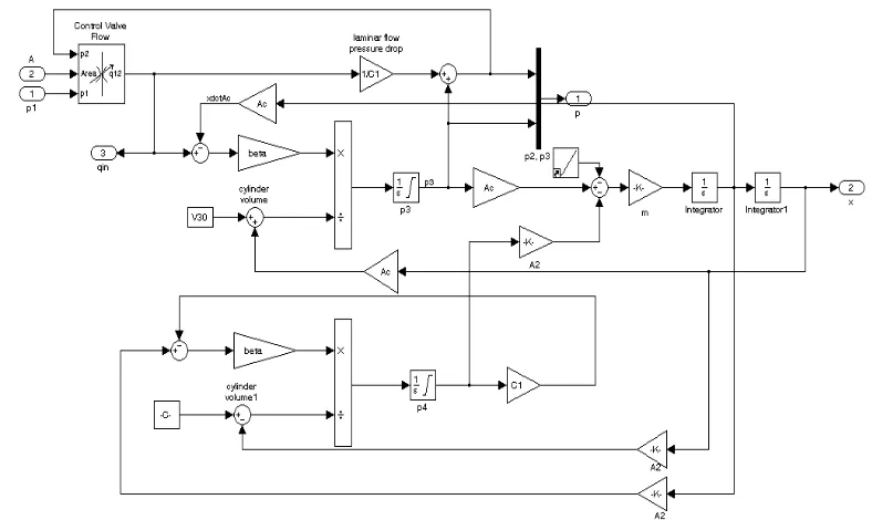
2 4.Figure 7 shows the valve and hydraulic cylinder sub-block obtained from Equations (1) to (6). The control valve is modeled as turbulent flow through a variable area orifice. A system of differential-algebraic equations models the cylinder pressurization with the pressure p1 and p2, which appear as derivatives in Equations (4) to (6) and are used as the states.
Figure 7. Simulink Block of Hydraulic Cylinder and Valve
Figure 8. Simulink Block of Fuzzy Adaptive Controller
4.2. Simulation Results
Table 2. Parameter Values for Simulation
Symbol Explanation Value
Cd Discharge coefficient 0.61
e
Bulk modulus of hydraulic fluid. 6.85e8 PaA1 Cross-sectional area of the piston 1.23e-3 m2
A2 Annular area of piston rod chamber 5.91e-4 m
2
ρ Fluid density 800 kg/m3
Cic Internal leakage coefficient 3e-11
Cec External leakage coefficient 2e-11
m Equivalent mass 500 kg
Ps Hydraulic supply pressure 2.5e6 Pa
V01 Original total fluid volumes of the forward cylinder chamber 2.4e-3 m3
V02 Original total fluid volumes of the return cylinder chamber 0.0089 m3
2
OP The length of OP2 3.08 m
2 3
Simulation was performed in Simulink software to investigate the performance of fuzzy adaptive PID controller for erection system. The simulation results are demonstrated in this section. The parameters used for numerical simulation are shown in Table 2.
The goal of the controllers is to get the system tracking the desired angle reference. Figure 9 shows the simulation results of erection angle controlled by the fuzzy logic, PID and fuzzy adaptive PID controllers respectively. Figure 9(a) presents desired and actual erection angle curves. Figure 9(b) illustrates the tracking errors of desired and actual erection angles. It is clearly shown that the angle tracking error of fuzzy adaptive PID controller is the smallest. The PID controller exhibits a phase lag and the tracking error of the fuzzy logic controller fluctuates wildly. Fuzzy adaptive PID controller clearly performs better than fuzzy logic and PID controllers. It has the advantage of both PID and fuzzy logic controllers and is able to cope with parameter changes. We can obtain that the erection system tracks the reference angle trajectory very well with the fuzzy adaptive controller.
(a) Desired and Actual Erection Angle of Simulation
(b) Tracking Error of Desired and Actual Erection Angle of Simulation
Figure 9. Simulation Results of Erection Angle
5. Experimental Verification
Figure 10. Mechanical Constitution of the Platform
0 10 20 30 40 50 60 70 80 90
0 20 40 60 80 100
Time(s)
A
ngl
e
(de
g)
Fuzzy adaptive PID PID
Fuzzy logic Desired angle
0 10 20 30 40 50 60 70 80 90
-0.1 -0.05 0 0.05 0.1 0.15 0.2 0.25
Time(s)
A
ngl
e
(de
g)
Fuzzy adaptive PID PID
Mechanical constitution of laboratory equipment is shown in Figure 10. It is mainly composed of erection arm and erection cylinder. Programs of data acquisition and fuzzy adaptive PID controller are completed in LabVIEW software.
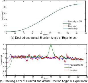
Figure 11 shows experimental results of erection angle controlled by fuzzy logic, PID and fuzzy adaptive PID controllers respectively. Figure 11(a) presents desired and actual erection angle curves. Figure 11(b) illustrates the tracking error of desired and actual erection angle. From the results we can obtain that the tracking error of PID controller is the largest. The tracking error of fuzzy logic controller fluctuates wildly. The tracking error of fuzzy adaptive PID controller is small and steady. It can be concluded from the experimental results that the performance of fuzzy adaptive PID controller is the best compared with fuzzy logic and PID controllers.
(a) Desired and Actual Erection Angle of Experiment
(b) Tracking Error of Desired and Actual Erection Angle of Experiment
Figure 11. Experimental Results of Erection Angle
6. Conclusion
In this paper, mathematical model of the electro-hydraulic system is derived. Kinetic analysis of erection mechanism is presented. Fuzzy adaptive PID controller is applied to erection mechanism in combination of fuzzy logic and PID control method. The model of erection mechanism is established in Simulink. Simulation and experimental results of erection angle controlled by fuzzy logic, PID and fuzzy adaptive PID controllers are respectively obtained. It is clearly shown that the angle tracking error of fuzzy adaptive PID controller is the smallest. Hence, it can be concluded that fuzzy adaptive PID controller is suitable for erection mechanism.
Acknowledgement
This research was financially supported by the National Natural Science Foundation of China (Grant No. 51475462).
0 10 20 30 40 50 60 70 80 90
0 20 40 60 80 100
Time(s)
A
ngl
e
(de
g)
Fuzzy adaptive PID PID
Fuzzy logic Desired angle
0 10 20 30 40 50 60 70 80 90
-0.8 -0.6 -0.4 -0.2 0 0.2 0.4 0.6
Time(s)
A
ngl
e
(de
g)
Fuzzy adaptive PID PID
References
[1] Merritt HE. Hydraulic Control Systems. New York: John Wiley & Sons. 1967: 10-15.
[2] Chang SO, Lee JK. The Design of a Real-time Simulator on the Hydraulic Servo System. International Journal of Precision Engineering and Manufacturing. 2003; 4(1): 9-14.
[3] Davliakos I, Papadopoulos E. Model-based Control of a 6-dof Electro-hydraulic Stewart–Gough Platform. Mechanism and Machine theory. 2008; 43(11): 1385-1400.
[4] Barai RK, Nonami K. Optimal Two-degree-of-freedom Fuzzy Control for Locomotion Control of a Hydraulically Actuated Hexapod Robot. Information Sciences. 2007; 177(8): 1892-1915.
[5] Guan C, Pan S. Adaptive Sliding Mode Control of Electro-hydraulic System with Nonlinear Unknown Parameters. Control Engineering Practice. 2008; 16(11): 1275-1284.
[6] Rahmat MF, Has Z, Husain AR, et al. Modeling and Controller Design of an Industrial Hydraulic Actuator System in the Presence of Friction and Internal Leakage. International Journal of the Physical Sciences. 2011; 6(14): 3502-3517.
[7] Jones E, Dobson A, Roskilly AP. Design of a Reduced-rule Self-organizing Fuzzy Logic Controller for Water Hydraulic Applications. Proceedings of the Institution of Mechanical Engineers, Part I: Journal of Systems and Control Engineering. 2000; 214(5): 371-382.
[8] Chatzakos P, Papadopoulos E. On Model-based Control of Hydraulic Actuators. Proceedings of RAAD. 2003; 3: 7-10.
[9] Gao X, Feng Z J. Design Study of an Adaptive Fuzzy-PD Controller for Pneumatic Servo System. Control Engineering Practice. 2005; 13(1): 55-65.
[10] Karpenko M, Sepehri N. Robust Position Control of an Electrohydraulic Actuator with a Faulty Actuator Piston Seal. Journal of Dynamic Systems, Measurement, and Control. 2003; 125(3): 413-423.
[11] Jelali M, Kroll A. Hydraulic Servo-Systems: Modelling, Identification and Control. Berlin: Springer Science & Business Media. 2012: 21-30.
[12] Truong DQ, Ahn KK. Force Control for Hydraulic Load Simulator Using Self-tuning Grey Predictor– fuzzy PID. Mechatronics. 2009; 19(2): 233-246.
[13] Chen CY, Liu LQ, Cheng CC, et al. Fuzzy Controller Design for Synchronous Motion in a Dual-cylinder Electro-hydraulic System. Control Engineering Practice. 2008; 16(6): 658-673.
[14] Adriansyah A, Gunardi Y, Badaruddin B, et al. Goal-seeking Behavior-based Mobile Robot Using Particle Swarm Fuzzy Controller. TELKOMNIKA (Telecommunication Computing Electronics and Control). 2015; 13(2): 528-538.
[15] Chiang MH, Chen CC, Kuo C F J. The High Response and High Efficiency Velocity Control of a Hydraulic Injection Molding Machine Using a Variable Rotational Speed Electro-hydraulic Pump-controlled System. The International Journal of Advanced Manufacturing Technology. 2009; 43(9-10): 841-851.
[16] Zheng J, Zhao S, Wei S. Application of Self-tuning Fuzzy PID Controller for a SRM Direct Drive Volume Control Hydraulic Press. Control Engineering Practice. 2009; 17(12): 1398-1404.
[17] Li L, Xie J, Huang J Z. Fuzzy Adaptive Sliding Mode Control of Large Erecting Mechanism. TELKOMNIKA Indonesian Journal of Electrical Engineering. 2013; 11(12): 7259-7268
[18] Cerman O, Hušek P. Adaptive Fuzzy Sliding Mode Control for Electro-hydraulic Servo Mechanism. Expert Systems with Applications. 2012; 39(11): 10269-10277.
[19] Pratumsuwan P, Thongchai S, Tansriwong S. A Hybrid of Fuzzy and Proportional-integral-derivative Controller for Electro-hydraulic Position Servo System. Energy Research Journal. 2010; 1(2): 62. [20] Kalyoncu M, Haydim M. Mathematical Modelling and Fuzzy Logic Based Position Control of an
Electrohydraulic Servo System with Internal Leakage. Mechatronics. 2009; 19(6): 847-858.
![Figure 5 [19]. Triangular shape function is chosen as output membership function which is shown in](https://thumb-ap.123doks.com/thumbv2/123dok/248158.503956/5.595.176.421.538.597/figure-triangular-shape-function-chosen-output-membership-function.webp)