LEADER FOLLOWER ROBOT
LAU WHY CHUONG
A report submitted in partial fulfillment of the requirements for the degree of Bachelor of Mechatronics Engineering
Faculty of Electrical Engineering (FKE) UNIVERSITI TEKNIKAL MALAYSIA MELAKA
I hereby declare that I have read through this report entitle “Leader Follower Robot” and found that it has comply the partial fulfillment for awarding the degree of Bachelor of Mechatronics Engineering
Signature : ………
Supervisor’s Name : ………
iii
I declare that this report entitle “Leader Follower Robot” is the result of my own research except as cited in the references. The report has not been accepted for any degree and is not concurrently submitted in candidature of any other degree.
Signature : ………
Name : ………
iv
ACKNOWLEDGEMET
I would like to express my gratitude to all that has helped me throughout for this project. First, I would like to thank to my supervisor, Dr. Ahmad Zaki Bin Hj Shukor for the guidance throughout the whole semester.
v
ABSTRACT
vi
ABSTRAK
vii
TABLE OF CONTENTS
CHAPTER TITLE PAGE
ACKNOWLEDGEMET iii
ABSTRACT iv
ABSTRAK v
TABLE OF CONTENTS vi
LIST OF TABLES ix
LIST OF FIGURES x
LIST OF APPENDICES xii
1 INTRODUCTION 1
1.1 Motivation 1
1.2 Problem Statement 2
1.3 Objectives 3
1.4 Scope 3
2 LITERATURE REVIEW 4
2.1 Introduction 4
2.2 Coordinated Control of Mobile Robots Based On Artificial Vision
4
2.3 A Distributed Multi-Robot Sensing System Using An Infrared Location System
6
2.4 Low Cost Sensing For Autonomous Car Driving In Highways
8
2.5 The X80 Robot 9
2.6 Vision-based Navigation of Mobile Robot with Obstacle Avoidance by Single Camera Vision and Ultrasonic Sensing
10
2.7 Comparison 12
viii
2.7.2 Specific criteria: Sensor 13
2.8 Conclusion 14
3 METHODOLOGY 15
3.1 Introduction 15
3.2 Description of the work 16
3.2.1 Project Flow Chart and Methodology 16
3.3 Components Selected 17
3.3.1 Sensor 17
3.3.2 Microcontroller 19
3.3.2 Motor 20
3.3.4 Material 21
3.3.5 Motor Driver 22
3.4 Prototype of Follower Robot 23
3.5 Experiment Setup 26
3.5.1 Experiment 1: Object Detection Using Infrared Sensor
26
3.5.2 Experiment 2: Tracking Object Using Ultrasonic Sensor
28
3.5.3 Experiment 3: Mobile Robot Turning Trajectory 29
3.5.4 Experiment 4: Tracking Control of Follower Robot for Moving Leader Robot
31
4 RESULTS, ANALYSIS AND DISCUSSION 32
4.1 Results, Analysis and Discussion 32
4.1.1 Experiment 1: Object Detection Using Infrared Sensor
32
4.1.1.1Sensitivity of Infrared Sensor 32
4.1.1.2 Detection Angle of Infrared Sensor 35
4.1.2 Experiment 2: Tracking Object Using Ultrasonic Sensor
38
ix
4.1.3.1 Turning direction to right side 41
4.1.3.2 Turning direction to left side 43
4.1.4 Experiment 4: Tracking Control of Follower Robot for Moving Leader Robot
45
4.1.4.1 Straight Line Trajectory 46
4.1.4.2 Straight Line Trajectory With Obstacles 48
4.1.4.3 S-shape Trajectory 50
4.1.4.4 S-shape Trajectory With Obstacles 52
4.1.4.5 U-shape Trajectory 54
4.1.4.6 U-shape Trajectory With Obstacles 56
4.1.4.7 Zigzag Trajectory 58
4.1.4.8 Zigzag Trajectory With Obstacles 60
5 CONCLUSION AND RECOMMENDATION 62
5.1 Conclusion and Future Work 62
REFERENCE 63
APPENDICES 65
Appendix A – Gannt Chart for FYP 1 and FYP 2 66
Appendix B – Ultrasonic Sensor 67
Appendix C – Infrared Sensor 70
Appendix D – Program in Follower Robot 72
x
LIST OF TABLES
TABLE TITLE PAGE
Table 2.1 Comparison of overall criteria 12
Table 2.2 Comparison of sensor used 13
Table 3.1 Comparison between DC, Stepper and Servo Motor 20
Table 3.2 Product specification from its datasheet 21
Table 4.1 Sensitivity of infrared sensors 33
Table 4.2 Angle of detection by the infrared sensors 36
Table 4.3 Effective angles of ultrasonic sensor 39
Table 4.4 Right side angles obtained with different time 41
Table 4.5 Left side angles obtained with different time 43
xi
LIST OF FIGURES
FIGURE TITLE PAGE
Figure 1.1 Fatalities in Mineral Exploration in Canada 1980 – 2012 2
Figure 2.1 Pioneer 2DX Mobile Robots 5
Figure 2.2 Block diagram of the infrared location system 7
Figure 2.3 The actual system and the illustration of mechanics 7
Figure 2.4 Occupancy grid for the sonar data 9
Figure 2.5 The X80 Robot 10
Figure 2.6 IR sensors on X80 Robot 10
Figure 2.7 YAMABICO robot 11
Figure 3.1 Overview of the whole project 16
Figure 3.2 Ultrasonic Sensor HC-SR04 18
Figure 3.3 Infrared Sensor Sharp GP2Y0A21 19
Figure 3.4 Arduino Uno 20
Figure 3.5 Micro Metal Gearmotor 21
Figure 3.6 Aluminium Chassis 22
Figure 3.7 2Amp Motor Driver Shield 22
Figure 3.8 Top view of mobile robot 23
Figure 3.9 Front view of mobile robot 24
Figure 3.10 Side view of mobile robot 24
Figure 3.11 Back view of mobile robot 25
Figure 3.12 The experimental setup for sensitivity test 27
Figure 3.13 The experimental setup for angle detection 27
Figure 3.14 The experimental setup for determine effective angles of
ultrasonic sensor. 28
Figure 3.15 The experimental setup for turning right side 29
Figure 3.16 The experimental setup for turning left side 30
Figure 4.1 Graph of sensitivity of the IR sensor when object at different
xii
Figure 4.2 Graph of angle against voltage 37
Figure 4.3 Graph of angle against average distance from ultrasonic sensor 40
Figure 4.4 Graph of average angle against length of time for turning right
side 42
Figure 4.5 Graph of average angle against length of time for turning left
side 44
Figure 4.6 Trajectory in straight line 46
Figure 4.7 General view of graphical form of trajectory in straight line 47
Figure 4.8 Zoom in view of graphical form in straight line trajectory 47
Figure 4.9 Trajectory in straight line with obstacles 48
Figure 4.10 General view of graphical form of trajectory in straight line
with obstacles 49
Figure 4.11 General view of graphical form of trajectory in straight line
with obstacles 49
Figure 4.12 Trajectory in S-shape 50
Figure 4.13 Graphical form of trajectory in S-shape 51
Figure 4.14 Trajectory in S-shape with obstacles 52
Figure 4.15 Graphical form of trajectory in S-shape with obstacles 53
Figure 4.16 Trajectory in U-shape 54
Figure 4.17 Graphical form of trajectory in U-shape 55
Figure 4.18 Trajectory in U-shape with obstacles 56
Figure 4.19 Graphical form of trajectory in U-shape with obstacles 57
Figure 4.20 Trajectory in Zigzag 58
Figure 4.21 Graphical form of trajectory in Zigzag 59
Figure 4.22 Trajectory in Zigzag with obstacles 60
xiii
LIST OF APPENDICES
APPENDIX TITLE PAGE
A Gannt Chart for FYP 1 and Gannt Chart for FYP 2 66
B Ultrasonic Sensor 67
C Infrared Sensor 70
D Program in Follower Robot 72
1
CHAPTER 1
INTRODUCTION
1.1 Motivation
Nowadays, mobile robots are becoming more heavily used in environments especially in industry field where human involvement is limited, dangerous or impossible. Different levels of complexity of the robots are built to perform multiple tasks that are required. These robots perform in more dangerous and strenuous human tasks and lead to greater efficiency and accuracy, saving both time and resources [1].
Robots are best at performing the same job every time repeatedly. Such jobs are programmed and the performance is reliable and consistent. Humans usually will get worn out from repetitive jobs and suffer from repetitive motion injuries. Human’s tiredness and error will lead to fatal accidents and drop the performance of the tasks.
2
Figure 1.1: Fatalities in Mineral Exploration in Canada 1980 – 2012 [2]
To overcome this problem, robots are required to cooperate with each other to replace human tasks. One of the key elements for the multiple robots to work together is the ability of robot to follow other robot. This element leads to study of leader and follower behavior.
1.2 Problem Statement
Nowadays, robotic technologies have become very important since many industries are trying to improve their performance. This technology has developed many years to make sure an excellent impact. Recently, the robots have been invented to help peoples running their daily life to get the better life.
3
following task. These problems include the accuracy of tracking the robot when the leader is moving, the distance to avoid collisions between leader and follower and the capability to avoid the obstacles. Besides, the response time of the follower when the moment the leader is moving.
1.3 Objectives
1. To design leader follower robot.
2. To determine the sensitivity of sensors used.
3. To implement the concept of an obstacle avoidance and collision avoidance with leader.
4. To perform validation test of follower based on leader’s trajectory.
1.4 Scope
1. To implement the ultrasonic sensors and infrared sensors. 2. The collision avoidance with only one leader.
3. The leader and follower robot are run on flat floor. 4. Able to avoid a small size obstacle.
4
CHAPTER 2
LITERATURE REVIEW
2.1 Introduction
This chapter review some of the robots that were built to perform the task following. The advantages and disadvantages for each of the robot are also included in the review.
2.2 Coordinated Control of Mobile Robots Based On Artificial Vision
According to [3], in this project, is a coordinated control strategy of multiple robots based on artificial vision to measure the relative position between them, in order to achieve and maintain the specified formation. A leader robot is given that moves about an unknown trajectory and unknown speed. In order to maintain the robots with certain distance between the leader, a controller is designed by using visual information about the position of the leader robot. At equilibrium point, the control system is proved to be stable which achievement of the navigation objective. Experimental results with a leader robot and a follower robot, are included to show the performance based on the vision control system.
5
The image of four pattern marks square of know side length that mounted on the leader will be captured by the camera. The image’s height of the horizontal median of this square is coinciding with height of the image’s camera centre. The location of the leader and the relative position between the leader and a follower robots can be calculated from the image captured by vision system.
Experiments were carried out with two Pioneer 2DX Mobile Robots which has its own control system. The vision system includes a frame grabber PXC200 that allows capturing the images from a camera SONY EV-D30 mounted on the follower robot. These images are transmitted from the follower robot to a Pentium II-400 MHz PC, in charge of processing the images and of calculating the corresponding control actions. From this image, the centroids of the four projected pattern’s marks are calculated and used to compute the variables needed by the controller. Finally, the computed control actions are sent by a transmitter to the follower robot.
However, this method has the limitation that the leader robot mounted with pattern’s mark need to be made to coincide with the height of the image’s camera centre. The image will not transmit by the follower robot if the centroid of each mark is not capture. The follower robot also could not avoid obstacle if there is obstacle in between the leader and follower robot. The cost will be expensive due to complex hardware need to be implemented.
Figure 2.1: Pioneer 2DX Mobile Robots [3]
6
According to [4], in this project, the distributed multi-robot sensing system using the infrared location system. The relative positions are estimated using intensity and bearing measurements of the received infrared signals. Fusing the position estimated among robots to obtain the relative orientations. The location system enables a group of robots to perform distributed and cooperative environment sensing by maintaining a given formation while the group measures distributions of light and magnetic field. In the experiments, a group of three robots moves and collects spatial information (i.e. illuminance and compass heading) from the given environment. The information is stored into grid maps and illustrated in the figures presenting illuminance and compass heading.
The infrared location system enables the robots to maintain given formation while sensing the environment. The relative position can be estimated without data transmission between robots. However, the relative orientation needs the data transmission. Estimation of the radial and angular coordinates, respectively, of the other robots in polar coordinates are using intensity and bearing measurements of the signals received. Each robot can be identified through different frequencies in the received signals.
7
Figure 2.2: Block diagram of the infrared location system [4]
One microcontroller estimates the position of detected and identified robot using an intensity of the received signal and a bearing of the beam collector. The other controls the speed of the beam collector using a discrete PID controller. The microcontrollers exchange information containing a bearing of the beam collector to be used in position estimation and a modulation frequency setup which defines the identification frequency of the robot.
Figure 2.3: The actual system and the illustration of mechanics [4]
8
target is near. Noises in the infrared location system and irregular ground will result in position error. The accuracy of the infrared location system and the leader’s odometry will affect the accuracy of the spatial measurements in coordinates. However, there is advantage using infrared sensor method which is low cost compare to vision system. The accuracy of detection for collision avoidance is better that using vision system.
2.4 Low Cost Sensing For Autonomous Car Driving In Highways
According to [5], this project, a car like robot equipped with a system called HANS able to following the road, performing trajectories and safe manner. Besides that, also can keep the safe distance between leader and follower and perform the avoiding obstacles. The experiment was conducted to test the system in both simulation and in a laboratory environment. As a result, these autonomous robots can perform the leader follower behaviour. It is assumed that there are no others car driving faster than HANS vehicle which mean no cars will appear from behind.
HANS using a low resolution web camera located in the centre of the mobile robot behind the rear view mirror and a set of sixteen ultrasonic sensors. The camera functions as a vision system to detect the objects that nearby. It used to detect the side lines that bound the traffic lanes, position and orientation of the robot and distance between robots.
9
Figure 2.4: Occupancy grid for the sonar data [5]
In this project, the cost is expensive due to use of many ultrasonic sensors. Besides that, the camera is using low resolution web. The low visibility due to light reflection and occlusion due to other vehicles in the road are the common problem.
2.5 The X80 Robot
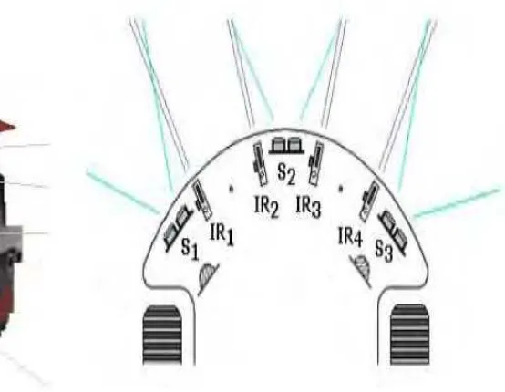
According to [6], this project presents a control strategy that responds to the requirement of the leader following task. The X80 Robot have two discrete PID controllers, located at each wheel’s motor and the data used by the controllers was transmitted from the infrared sensors. When one of the infrared sensors loses the object, an algorithm was conceived to provide the inputs for the controllers. A faulty infrared sensor was detected by using a fault detection scheme that using the information of another sonar sensor. A result of an implementation on the X80 mobile robot was presented.
The robot also has 4 infrared sensors and 4 sonar sensors to perform the following
10
The limitation of the robot is the response of the robot is not fast enough then the follower robots can be lost. The follower will lost the target if the environment space full with the obstacles. Another limitation is that the follower robot needs to stop during when leader is turning direction. Despite its limitation, the X80 robot can follow the leader robot at low speed in free space.
2.6 Vision-based Navigation of Mobile Robot with Obstacle Avoidance by Single Camera Vision and Ultrasonic Sensing
According to [7], this project describes a vision-based navigation method for an autonomous mobile robot, YAMABICO robot, which can perform the obstacles avoidance. In this method, model-based vision system is used for self-localization of the robots and non-stop navigation is achieved through retroactive position correction system. By combination of these two systems, the direction of safe passage can be calculated in the presence of obstacles.
Figure 2.5: The X80 Robot [6] Figure 2.6: IR sensors on X80 Robot
11
First, the robot will renders an expectation image to estimate the location. Next, extract both model edges for expectation image and camera image and compare through an extended Kalman Filter. Navigate with dead reckoning, meaning that the robot will update its position. The wheel encoders will supply the information to the system. Stationary obstacles are avoided with single-camera vision and moving obstacles are detected with ultrasonic sensors.
The advantage of this method is the view angles of two sensors systems are nearly identical 60 degrees. The ultrasonic sensors can detect obstacles with range of 50cm from robot. Vision sensor detects stationary obstacles at ranges far exceeding 50cm.
![Figure 1.1: Fatalities in Mineral Exploration in Canada 1980 – 2012 [2]](https://thumb-ap.123doks.com/thumbv2/123dok/487316.53584/15.595.98.512.71.351/figure-fatalities-in-mineral-exploration-in-canada.webp)
![Figure 2.1: Pioneer 2DX Mobile Robots [3]](https://thumb-ap.123doks.com/thumbv2/123dok/487316.53584/18.595.176.434.477.661/figure-pioneer-dx-mobile-robots.webp)
![Figure 2.3: The actual system and the illustration of mechanics [4]](https://thumb-ap.123doks.com/thumbv2/123dok/487316.53584/20.595.131.512.442.635/figure-actual-illustration-mechanics.webp)
![Figure 2.4: Occupancy grid for the sonar data [5]](https://thumb-ap.123doks.com/thumbv2/123dok/487316.53584/22.595.188.422.69.236/figure-occupancy-grid-for-the-sonar-data.webp)
![Figure 2.7: YAMABICO robot [7]](https://thumb-ap.123doks.com/thumbv2/123dok/487316.53584/24.595.190.427.322.499/figure-yamabico-robot.webp)
