"I have read this thesis and in my opinion, it is suitable in term of scope and quality for the purpose of awarding Bachelor Degree in EJectronic Engineering ( Industrial
Signature
Name of Supervisor Date
ELECTROMAGNETIC LEVITATION DEMONSTRATOR
rusmeyatibセinordin@
This Report Is Submitted In Partial Fulfillment Of Requirements For The Bachelor Degree of Electronic E ngineering ( Industrial Electronic)
Fakulti Kejuruteraan Elektronik dan Kejuruteraan Komputer Kolej Universiti T ekrnlcal Kebangsaan Malaysia
Jl
"I hereby declare that this thesis is the result of my own effort except as clearly stated in the sources of reference"
Signature Writer Date
llJ
First and foremost, I would like to express my deepest gratitude to my supervisor Mr. Ho Yih Hwa for his supervision and invaluable guidance throughout this work.
I am most grateful to my lovely parents for being understanding and supportive in whatever decision I made.
A special thanks to En. Mohd Razi bin Y aacob for his supported and En. Aini for his
JV
ABSTRACT
Electromagnetic Levitation System had become a fast develop technologies
providing environmentally benefit solutions for industry and transportation. This project
is develop a Electromagnetic Levitation Demonstrator consist of two photo-detector and
one lifting coil. It is demonstrated how an electromagnetic can floating I pulls a steel ball
upward Wltil it interrupts a light beam that falJs on the photo-detector and how the coil effect to electromagnetic levitation demonstrator but this system can only reach out a
few short centimeter and anything further might as well be infinity. This device need a
design and construct the circuit such as the coil driver and the different amplifier circuit,
Infrared emitter and Photo-detector ciicuit, the reference voltage and phase lead network
v
ABSTRAK
Sistem Pengapungan Elektromagnetik menjadi satu tecknologi yang berkembang
pesat dan menyediakan pelbagai faedah penyelesaian untuk industri dan pengangkutan.
Projek ini menunjukkan Sistem Pengapungan Elektromagnetik yang terdiri daripada dua
pengesan cahaya dan satu gegelung pengangkat Ia menunjukkan bagaimana elektomagnetik tersebut boleh mengapungkan I menarik bebola Jogam naik ke atas
hingga biasan sinar cahaya terhadap pengesan cahaya yang akan menjatuhk:annya dan bagaimana gegelung pengangkat akan memberi kesan kepada penunjuk Sistem
Pengapungan Elektomagnetic ini. Sistem ini hanya boleh digunakan untuk jarak yang
.
pendek iaitu dalam beberapa sentimeter dan sebarang tambahan jarak seterusnya akan
menjadi ifiniti. Projek ini memerlukan rekaan dan susunan litar seperti litar pemacu gelung, htar penguat pembezaan, litar pemancara inframerah, litar pengesan cahaya, litar untuk voltan rujukan, litar penunjuk fasa dan memerlukan rekaan bagi gegelung
CONTENT
CHAPTER TITLE
PROJECT TITLE ACKNOWLEDGEMENT DEDICATION ABSTRACT ABSTRAK CONTENT
LIST OF TABLE
LIST Of FIGURE
I INTRODUCTION
l . l Introduction 1.2 Project Objective
1.3 Scope Project
n
LITERATURE REVIEW2.1 Introduction
2.1.1 Background of magnetic levitation
demonstrator
2.2.2 Electromagnetic Levitation
VI I
m
ELECTROMAGNETIC MODULE3.1 Introduction 9
3.2 Flow Diagram of Electromagnetic
Levitation System 12
3.2.1 Input 12
3.2.2 Emitter 13
3.2.3 Signal Detector 14
3.2.4 Reference Detector 15
3.2.5 Difference AmpJifier 16
3.2.6 Loop Control 17
3.2.6.1 Benefit of Feedback 18
3.2.7 Loop Equations 19
3.2.7.1 Loop Gain 20
3.2.7.2 Transfer Function 21 3.2.8 Non Inverting Amplifier 22
3.2.9 Coil Driver 23
3.2.9.1 Specification for Lifting Coil 25
3.2.9.2 Coil Core 25
3.3 Power Supply 26
3.3.1 Coil Driver Supply 27
3.4 List of Component 28
VlJJ
IV RESIJLT
4.1
Introduction33
4.1.1
Bode Plot of Phase Lead Network33
4.2
Measurement35
4.3
Design circuit at Printed Circuit Board36
4.4
Casing36
4.4.1
Material List37
4.4
Electromagnetic levitation demonstratedoperation
38
4.5
How the Coil Wor1cs39
v
DISCUSSION AND CONCLUSSION5.1
Discussion41
5.1.1
Winding Wire41
.
5.1.2
Weight of the steel ball42
5.2
Conclusion42
5.3
Future Development43
REFERENCE
45
IX
LIST OF TABLE
NO. TITLE PAGE
3.1 Voltage Requirements 27
3.2 List of Component and Equipment in
Electromagnetic Levitation System 29
3.3 The Absolute Maximum Rating of LM741 31
3.4 Absolute Maximum Rating of Transistor
NPN2N3055 32
X
LIST OF FIGURE
NO TITLE PAGE
2.1 An Electromagnetic 7
3.1(a) Overall Process Flow 10
3.1(b) Flow Process ofElectromagnetic Levitation System 11 3.2 Flow Diagram of Electromagnetic Levitation System 12
3.3 Emitter Circuit 13
3.4 Signal Detector circuit 14
.
3.5 Flow Diagram For Signal Detector to
Voltage Follower 15
3.6 Reference Detector Circuit 15
3.7 Difference Amplifier Circuit 16
3.8 Feedback Control System 19
3.9 Transfer function Circuit 21
3.10 Non Inverting Amplifier circuit 22
3.11 Coil Driver Circuit 23
3.12 Transistor NPN 2N3055 24
3.13 Coil Core 26
3.14 Power Supply separated 28
3.15 Connection Diagram ofLM741 30
3.16 Internal Schematic Diagram of Transistor
NPN2N3055 32
XI
4.2
Phase Lead Network Circuit34
4.3
Signal and Reference Detector Measurement35
4.4 Casing
37
4.5 Electromagnetic Levitation demonstrated
39
CHAPTER I
INTRODUCTION
1.1 INTRODUCflON
.
photo-2
detector as a signal and reference, and a ljfting coil to produce magnetic field current to
pull a steel baH floating in the air.
1.2 PROJECT OBJECTIVE
The project objective is to demonstrated the concept of electromagnetic
levitation system by using two photo-detector and lifting coil and to produces the low
cost of electromagnetic levitation demonstrator. This electromagnetic levitation system
is selected and was build by follow their specification. The specification are to build a
magnetic coil which can produce an electromagnetic force carries with 2A of current,
and to definitely with Jess current the steel ball will move downward and when the high
current the steel baiJ will move upward
1.3 SCOPE PROJECT
This project built to studies and construct the emitter circuit, reference detector
circuit, photodetector circuit, different amplifier circuit, design the lifting coil, design the
signal detector circuit, design the non inverting amplifier circuit and design the phase
CHAYrER
n
LITERATURE REVIEW
2.1 INTRODUCTION
This chapter discuss about how the steel ball can float in the air by using the lifting coil and two photodetector which produce the magnetic force into this device. The magnetic levitation demonstrator is the simple structure an is based on electromagnetic science by Sarnuel Earnshaw Theorem. In his theorem expressed the perversity of inanimate of magnetic objects.
When we hold two permanent magnets close together, you see that one of them will
jump strongly toward from the other. It explains this frustrating behavior will
always prevent you from suspending otze permanent magnet above or below
another, no matter how one arranges the two magnets. However, an active control
circuit can get around this problem by rapidly adjusting the magnet's strength.
4
The basic principles is to used a current to manipuJate electromagnetic power which can counteract the weight of the steel ball and keep it suspended in the air.
2.1.1 BACKGROUND OF MAGNETIC LEVITATION DEMONSTRATOR
5
2.1.2 ELECTROMAGNETIC LEVITATION
The electromagnetic system keeps a steel ball suspended in the air by countering the balls weight with electromagnetic force which can be expressed as the dynamic following formula in an upward direction according to Newton' s law.
F = mg (2.1)
where m is the weight of the ball, g as a gravitational constant and F is the force produce from electromagnetic coil. The magnetic field generated by current and calculated from Ampere' s Law or Biot-Savart Law are characterized by magnetic field Band the unit is in Testa. When the generated field pass through the magnetic materials which contribute internal magnetic field, ambiguities can arise a part of the field from external current and the materials. The magnetic ·field strength had defined as another magnetic field quantity designated as H, and the relation ship is:
H = B / Jlo (2.2)
and if the value of unambiguous designated the driving magnetic influence from extend current in a material, independent of the material magnetic response. The relationship of 8 can be written in the equivalent form:
6
Hand M wiJI have the same units, amperes'/meter. The relationship in eq. (2.3) holds for all material whether they are linear or not For linear materials, M in (Aim) depends linearity on H such that
M = XmH (2.4)
where Xm is a dimensionless quantity ( ratio of M to H ) called magnetic susceptibility of the medium. It is more or less a measure of how susceptible or sensitive the material is to a magnetic field Substituting eq. (2.4 ) into eq. (2.3) yields:
B = JJQ(J + Xm ) H = Jili (2.5) or
B = JJQ 14H (2.6)
The quantity J.1
=
JJo J.lr is called the permeability of the material and is measured in henry's/meter, the henry is theunit
of inductance and will be defined a little later. The dimensionless quantity Jlr is the ratio of the permeability of a given material to that of free space and is known as a relative permeability of the material and JJQ being the magnetic free space permeability J.1o = 4n x l 0 -7. The magnetic force will produce the electromagnetic flux for the magnetic circuit The magnetic force produce flux with Iwhich called as flux path.
7
for a circular path : /=27tr
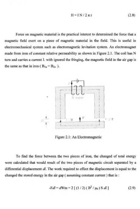
H=IN I 21tr (2.8)
Force on magnetic material is the practical interest to determined the force that a magnetic field exert on a piece of magnetic material in the field. This is useful in electromechanical system such as electromagnetic levitation system. An electromagnet made from iron of constant relative permeability as shown in Figure 2.1. The coil bas N turn and carries a current I. with ignored the fringing, the magnetic field in the air gap is the same as that in iron ( B1n = B2n ).
-I-
---,\ I I II
- t
I 1 l I·MMセ@
セMMM
セ }@
Figure 2.1: An Electromagnetic
To find the force between the two pieces of iron, the changed of total energy were calculated that would result of the two pieces of magnetic circuit separated by a differential displacement dl. The work required to effect the displacement is equal to the changed the stored energy in the air gap ( assuming constant current ) that is :
[image:19.562.71.530.76.758.2]8
where S is the cross-sectional area of a gap, the factor two accounts for the two air gaps. And the negative sign indicates that the force acts to reduce the air gaps ( or that the force is attractive). Thus
F = -2 ( B2 S / 2 J.1o) (2.10)
The force is exerted on the lower piece and not and the cWTent-carrying upper piece giving
rise
in to the field The tractive force across a single gapcan
be obtained from eq.(2.10) as(2 .11)
This equation can be used to calculated the forces in many types of devices including in electromagnetic levitation system. The tractive pressure in ( N/m2 ) in a magnetic surface is
(2.12)
CHAPTERID
SYSTEM DESJGN
3.1 INTRODUCTION
.
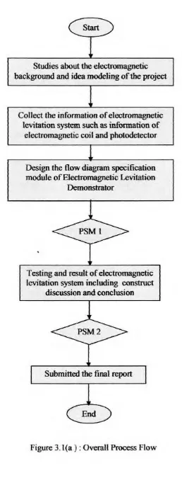
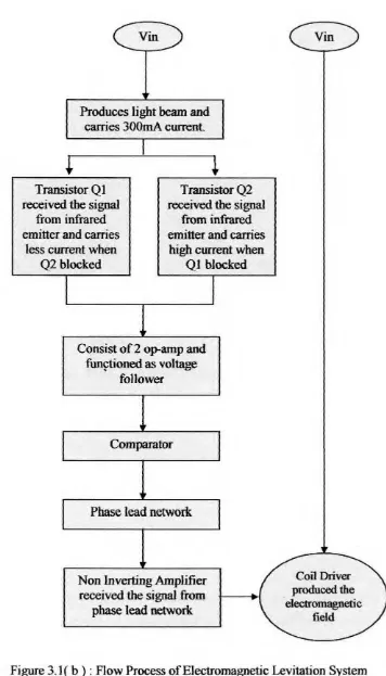
This chapter explained about the overall process flow and construction to build the electromagnetic levitation demonstrator in Figure 3.1(a) from start until progress the fmal report, to design the circuit and to make sure the objectives of this project successfully done. Figure 3. 1 (b) show the flow process of electromagnetic levitation system functioned and their specifications, This system used the looping system as phase lead network to reduced the coil strength to allow the ball to go down but doesn't turn to
the coiJ until the ball is past the reference spot This system also used the transfer
Studies about tbe electromagnetic background and idea modeling of the project
Collect the information of electromagnetic levitation system such as information of
electromagnetic coil and photodetector
Design the flow diagram specification module of Electromagnetic Levitation
Demonstrator
Testing and result of electromagnetic levitation system including construct
discussion and conc1usion
Submitted the final report
Figure 3.l(a ): Overall Process Flow
[image:22.559.171.429.35.720.2]Produces light beam and carries 300mA cwrent.
セ@
Transistor Q 1 received the signal
from infrared emitter and carries
less current when Q2 blocked
Transistor Q2 received the signal
from infrared emitter and carries high current when
QJ blocked
Consist of2 op-amp and funftioned as voltage
fo1lower
Comparator
Phase lead network
Non Inverting Amplifier received the signal :from
phase lead network
Coil Driver produced the electromagnetic
field
Figure 3.1 ( b ) : Flow Process of E1ectromagnetic Levitation System
[image:23.559.128.484.50.673.2]12
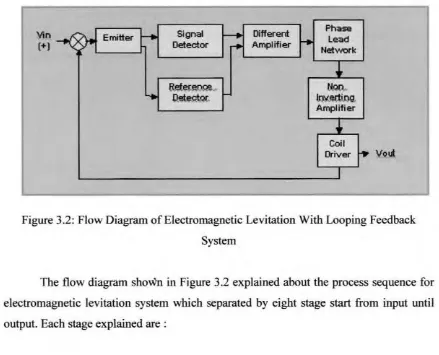
3.2 FLOW DIAGRAM OF ELECTROMAGNETIC LEVITATION SYSTEM
'lin
(+)
Signal
Detector
Different Amplifier
Phase Lead
Net-work
セ@
セ@
Amplifier
Coil
[image:24.562.71.510.113.468.2]vッセ@
Figure 3.2: Flow Diagram of Electromagnetic Levitation With Looping Feedback System
The flow diagram shoWn in Figure 3.2 explained about the process sequence for electromagnetic levitation system which separated by eight stage start from input until output. Each stage explained are :