DETERMINATION OF VIBRATION INPUT POWER FROM A STRUCTURE-BORNE SOURCE
MEOR MUHSIN BIN FADZIL
This Report Is Submitted In Partial Fulfillment of Requirement for the Bachelor Degree of Mechanical Engineering (Structure and Material)
Faculty of Mechanical Engineering Universiti Teknikal Malaysia Melaka
SUPERVISOR DECLARATION
“I admit to have read this report and it has followed the scope and quality in Partial Fulfillment of Requirement for the Degree of Bachelor of Mechanical Engineering
(Structure and Material)”
Signature: ... First Supervisor Name: ... Date: ...
ii
DECLARATION
“I hereby declare that the work in this report is my own except for summaries and quotations which have been duly acknowledged.”
iii
DEDICATION
To My Beloved Family
Fadzil B. Osman
Sharifah Fauziah Bt. Syed Basri
Meor Mohd Firdaus B. Fadzil
Nur Farhana Bt. Fadzil
Nurin Mursyidah Bt. Fadzil
Meor Mursyidi B. Fadzil
iv
ACKNOWLEDGEMENT
Firstly, my greatest gratitude to Allah, for His will, I managed to carry out this study. Thanks to Allah for giving me the good health and opportunity for me to completely finish this study on time. Then, for the most important person that play a big role in this study, I would like to dedicate my thousand of thanks to my supervisor Dr. Azma Putra for his guidance and support while I’m doing this research besides help me to find out the information to complete this research (PSM) in the given due date. He not just guides, but also teaches those things that I do not know.
I would like to dedicate my thanks to those who are directly or indirectly involve in making this report. Thanks to all other lecturer also that give me motivation and support in order to achieved the goal of this project. Special thanks to Mr. Hairul Nizam and Mrs. Nur Hidayah for teaching and guides me in using the lab equipments. Besides, I also want to thank to my panel for the presentation, Dr. Rozaidi and Mr. Hamzah for giving me a good critic and suggestion. From their suggestion, I manage to add my knowledge so that I become more understand about the project.
v
ABSTRAK
vi
ABSTRACT
vii
TABLE OF CONTENTS
CHAPTER TITLE PAGE
DECLARATION ii
DEDICATION iii
ACKNOWLEDGEMENT iv
ABSTRAK v
ABSTRACT vi
TABLE OF CONTENTS vii
LIST OF TABLES ix
LIST OF FIGURES ix
LIST OF SYMBOLS xi
LIST OF APPENDICES xii
CHAPTER I INTRODUCTION
1.1 Background of Study
1.1.1 Introduction of structural vibration 1.1.2 Sources of structure-borne sound in
building
1.1.3 Process of structural acoustic
1.1.4 Importance to know the input power (strength) of the source
1.2 Problem Statement 1.3 Objective of Study 1.4 Methodology 1.5 Scope of Study
viii
CHAPTER II THEORY
2.1 Mobility of A Thin Plate 2.2 Vibration Input Power 2.3 Reception Plate Method 2.4 Effective Mobility
12 13 16 18
CHAPTER III EXPERIMENTAL WORK 3.1 Experimental Methodology
3.1.1 Test rig fabrication: Receiver plate 3.1.2 Vibration source: Fan motor 3.1.3 Experimental Setup
3.1.3.1 Measurement of Source (motor) Mobility, YS 3.1.3.2 Measurement of Receiver
(plate) Mobility, YR 3.1.3.3 Measurement of Source
(motor) Squared Free Velocity, │ vf2│
3.1.3.4 Measurement of Receiver (plate) Squared Velocity, <v2>
19 19 22 23 25 26 26 27
CHAPTER IV RESULTS AND ANALYSIS 4.1 Measured Data
4.2 Measured From Reception Plate Method
28 34
CHAPTER V CONCLUSION AND RECOMMENDATIONS 38
REFERENCES 40
ix
LIST OF TABLE
NUMBER TITLE PAGE
Table 3.1 Materials list f test rig fabrication 20
Table 3.2 Electric fan motor specification 22
LIST OF FIGURE
NUMBER TITLE PAGE
Figure 1.1 A machine propagating vibration into structure 2
Figure 1.2 Structural acoustic process 5
Figure 1.3 Flow chart for the whole process 9
Figure 2.1 Free velocity and blocked force 14
Figure 2.2 A source connected to a receiver 14
Figure 3.1 Test rig parts 21
Figure 3.2 Completed test rig 22
Figure 3.3 Electric motor 23
Figure 3.4 Diagram of experimental setup 24
Figure 3.5 Motor hangs on a stand 25
Figure 3.6 Analyzer 25
Figure 3.7 Motor attach on the plate 27
x Figure 4.1 Effective mobility of motor (random phase) 28 Figure 4.2 Effective mobility of motor (zero phase) 29 Figure 4.3 Effective mobility of plate (random plate) 30 Figure 4.4 Effective mobility of plate (zero phase) 30 Figure 4.5 Comparison between source and receiver mobility 31 Figure 4.6 Spatial average mean square velocity of plate (motor
attached) 32
Figure 4.7 Damping loss factor from measurement 33
Figure 4.8 Comparison between direct measured and reception
plate for random phase (source mobility neglected) 34 Figure 4.9 Comparison between direct measured and reception
plate for zero phase (source mobility neglected) 35 Figure 4.10 Comparison between direct measured and reception
plate for random phase (source mobility included) 36 Figure 4.11 Comparison between direct measured and reception
xi
LIST OF SYMBOLS
Z = Impedance
Y = Mobility
YS = Mobility of source
YR = Mobility of receiver
vf = Free velocity
kb = Bending wave number
D = Bending stiffness per unit length
m = Mass per unit area
F = Excitation force
P = Vibration input power
dB = Decibel
ω = Frequency
η = Damping loss factor
xii
LIST OF APPENDIX
APPENDIX TITLE PAGE
1 Gantt Chart 45
2 Flow Chart 47
1
CHAPTER I
INTRODUCTION
1.1 BACKGROUND OF STUDY
Nowadays, we often heard about some failure in structure of a building which leads to building collapse. This failure can be caused by vibration from a rotating machine which is channeled to the structure. The damage of the entire structure is due to high amplitude of vibration at resonance. The most risky structure is the industrial or factory building structure which contains many vibrating machinery. Those machines are capable of injecting high level of vibration which is hazardous not only to the structure where the machines are installed but also to the machine itself. Thus, the structural health monitoring has been introduced [1].
2 Thus, it is difficult to determine the structure-borne vibration than the air-borne because there is many factors need to be considered. Therefore, an accurate prediction of the injected input power from such sources is required [4].
1.1.1 Introduction on Structural Vibration
Noise or vibration is a common occupational hazard in a large number of workplaces such as the iron and steel industry, foundries, saw mills, textile mills, airports and aircraft maintenance shops, crushing mills, among many others. Structural vibration control is the most important tool to diagnose and to determine the input power of structure-borne vibration. It is defined as a method to monitor and control an input power of vibration into structure of building (structure-borne) [5].
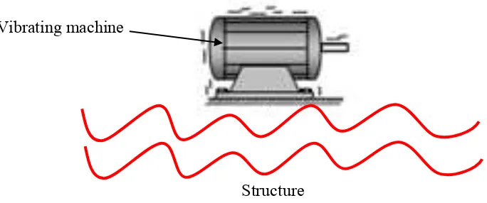
This is actually different from vibration monitoring technique that more focusing on machine vibration and its damage that can be avoid to reduce cost of maintenance. Structural vibration control here is more focus on the strength of vibration that was injected into building element. Good prediction of input power is necessary to avoid too many vibrations in building structure [6]. Figure 1.1 below shows the vibration from machine propagating into structure.
Figure 1.1: A machine propagating vibration into structure. Vibrating machine
3
1.1.2 Sources of Structure-Borne Sound in Building
There are low and high frequency noise that generated from the vibrating machine. Low-frequency noise from machinery in buildings tends to be of a structure-borne nature rather than an airborne nature [7].
In vibration acoustic problem, a ‘source’ itself is defined as a machine or machine component that creates vibration, which was connected to a receiver which is in this situation, refers to a support structure of the machine [8].
Since the structure-borne noise consist of a sources and receivers, there is three situations can be generally classified. Those situations are as follows:
a. A machine (source) installed in a particular environment (receiver) b. A machine component (source) inside a machine (receiver)
c. A sensitive piece of equipment (receiver) attached to a vibrating system (source)
In the first situation, the sources cause unwanted vibration at the source location or maybe remote from the source location. The examples of the sources are compressor in a building, exhaust fans, pumps and other rotating machines. The machine is installed directly on a structure that acts as a receiver.
4 a. Ventilation and exhaust fans
Fans are stated as a common vibration sources. It is because the joining of the component must be tightening enough or it will vibrate. Besides the joining, the bearing of the rotating shaft is also will create vibration if it not fits enough. Another cause is the misbalancing of the propeller itself. From the vibration, it also might produce a noise [11].
b. Compressor
Compressors are definitely very noisy machines that run in high pressure. This is because the compress air that entrapped in the casing and along the pipeline will produce vibration. It happens because the high pressure volume will tend to shake the internal component and thus, it will create a vibration. From the vibration, it also radiates into the air and creates noise which is another common occupational hazard in industry.
c. Electric motors
Vibration from electric motors is originated from several sources. It may cause by bearing that were loose and it have too much space to move and this will create vibration. Other sources are due to the misalignment of the shaft. When the shaft rotates, it will cause vibration because it tends to move up and down very fast. Other than that, the joining of all the parts and even at the mounting that are not tightening enough will also generate vibration. Those internal components vibrating will cause the casing to vibrate too [12].
d. Pneumatic tools
5
1.1.3 Process of Structural Acoustic
The process of structural acoustic can be divided into four stages [14]. Those processes were shown in the figure 1.2 below. The first stage is the generation stage. The vibration will be generated at the vibrating machines and will start to affect all the internal component of the machines which then increases the vibration.
The second stage is the transmission stage. Transmission is defined as the transfer of oscillatory energy from the generating mechanism to a structure. The vibration from the source will be transmitted into receiver through the contact points.
The third stage is called the propagation process. It concerns with the energy distributed throughout the whole structure system. This is when the vibration energy affected the entire structure, not just at the contact point.
The last stage is the radiation stage. In this stage, any structural part that was in a fluid environment (air) will radiate acoustic power which often known as audible noise. This noise is usually called structure-borne noise.
Figure 1.2: Structural acoustic process [15].
6
1.1.4 Importance To Know The Input Power (strength) of The Source
Vibration effect to a structure is rather vital although it is hard to see the process. The symptom before the structural damage is also sometimes not visible. That is why by knowing the input power of the vibration into structure from the sources; preliminary control measure can be planned. This will leads to a safer environment at the workplace and also cost saving [16].
From that prediction, knowledge about the condition of the supporting structure that holds the vibration sources can be obtained. Thus, a structural engineer should alert about this while planning to install any huge machine and need to ensure the support structure are strong enough to absorb potential vibration input power. This will give time to reinforce the structure or install some damper at the certain location which is at the contact points between structure and source [17].
7
1.2 PROBLEM STATEMENT
The input power from vibration into a structure is rather vital especially in industries. This supports the fact that vibration from machinery in industries can deteriorate the strength of a structure if the injected power level is too high.
Vibration control measure that is widely implemented in industries is mainly focusing on machinery vibration monitoring, for example to predict the health of a machine. Prediction of source strength, for example the potential of a machine to inject vibration power to a structure is lacking.
Therefore, a prediction method is required to determine the injected input power from a structure-borne source. From this, a control measure can be designed at an early stage.
1.3 OBJECTIVE OF STUDY
The objectives to be accomplished in this study are:
a. To determine the vibration input power to a structure based on mobility concepts using reception plate method.
8
1.4 METHODOLOGY
The study contains of several steps or methodology that covers both theoretical and experimental. The first step is to study the literatures that relate the theory of a vibration input power. Literature review consists of the previous researches made by other researcher from multiple sources such as journal; articles, academic books and others related references to obtain the theory.
After obtaining all the theory related, next step is the fabrication of the test rig. The rig was designed and fabricated in the workshop using appropriate materials with appropriate dimension.
The next step is to conduct an experiment according to the theory obtained. The experiment was carried out in laboratory with small machine which is a fan motor as the structure-borne source. The vibration strength represented by the free velocity was obtained from two methods namely the reception plate method and the direct measurement.
The data obtained from these two methods were then analyzed and compared. This is the important step of the study which includes accurate data analysis and discussion. Any assumption used is reviewed here.
9
Start
Introduction: Background, Problem statement, Objective, Methodology, Scope
Study on theory: Mobility, Excitation force, Vibration input power
Compiling: Sufficient information
A Yes
No
10
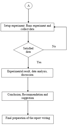
Figure 1.3: Flow chart for the whole process Setup experiment: Runs experiment and
collect data A
Experimental result, data analysis, discussion
Satisfied data
Conclusion, Recommendation and suggestion
Final preparation of the report writing Yes
11
1.5 SCOPE OF STUDY
There are several scopes and limitation needed to be considered in order to focus this project. The scopes represent the element that will only be covered in this study. Those elements are
a. Determination of vibration input power will be limited to an idealized receiver structures, namely plate.
![Figure 1.2: Structural acoustic process [15].](https://thumb-ap.123doks.com/thumbv2/123dok/585385.69665/18.595.116.527.464.523/figure-structural-acoustic-process.webp)