i
NUMERICAL DISPLAY USING PIC
MUHAMAD AZLAN BIN MOHAMAD MUJAINI
This report is submitted in partial fulfillment of the requirement for the award of Bachelor of Electronic Engineering (Industrial Electronics) With Honours
Faculty of Electronic and Computer Engineering Universiti Teknikal Malaysia, Melaka
ii
UNIVERSTI TEKNIKAL MALAYSIA MELAKA
FAKULTI KEJURUTERAAN ELEKTRONIK DAN KEJURUTERAAN KOMPUTER BORANG PENGESAHAN STATUS LAPORAN
PROJEK SARJANA MUDA II
Tajuk Projek : Numerical Display Using PIC
Sesi
Pengajian : 2008/2009
Saya MUHAMAD AZLAN BIN MOHAMAD MUJAINI (HURUF BESAR)
mengaku membenarkan Laporan Projek Sarjana Muda ini disimpan di Perpustakaan dengan syarat-syarat kegunaan seperti berikut:
1. Laporan adalah hakmilik Universiti Teknikal Malaysia Melaka.
2. Perpustakaan dibenarkan membuat salinan untuk tujuan pengajian sahaja.
3. Perpustakaan dibenarkan membuat salinan laporan ini sebagai bahan pertukaran antara institusi
pengajian tinggi.
4. Sila tandakan ( ) :
SULIT*
(Mengandungi maklumat yang berdarjah keselamatan atau kepentingan Malaysia seperti yang termaktub di dalam AKTA RAHSIA RASMI 1972)
TERHAD* (Mengandungi maklumat terhad yang telah ditentukan oleh organisasi/badan di mana penyelidikan dijalankan)
TIDAK TERHAD
Disahkan oleh:
__________________________ ___________________________________ (TANDATANGAN PENULIS) (COP DAN TANDATANGAN PENYELIA)
Alamat Tetap: Lot 4254 Jalan Pusara, Kampung Seri Tiram Jaya, 45500 Tanjong Karang, Selangor.
iii
“I hereby declare that this report is the result of my own work except for quotes as cited in the reference.”
Signature :
iv
“I hereby declare that I have read this report and in my opinion this report is sufficient in terms of the scope and quality for the award of Bachelor of Electronic
Engineering (Industrial Electronics) With Honours”
Signature :
v
vi
ACKNOWLEDGEMENT
Alhamdulillah, I am finally able to complete this final year project and the thesis as well within the allocated time. I would to take this opportunity to express my appreciation to some organizations and individuals who have kindly contributed to the successfully completion of my final year project. With the cooperation and contributions from all parties, the objectives of the project, soft-skills, knowledge and experiences were achieved accordingly.
I would like to convey my thanks to UTeM PSM organization committee especially my project supervisor, Prof. Abdul Hamid b. Hamidon for their co operation and involvement from the beginning until the end of my project development.
vii
ABSTRACT
viii
ABSTRAK
ix
TABLE OF CONTENTS
CHAPTER TITLE PAGE
PROJECT TITLE i
REPORT STATUS APPROVAL FORM ii
DECLARATION iii
DEDICATION v
ACKNOWLEDGEMENT vi
ABSTRACT vii
ABSTRAK viii
TABLE OF CONTENTS ix
LIST OF TABLES xii
LIST OF FIGURES xiv
LIST OF ABBREVIATIONS xvi
LIS OF APPENDICES xvii
I INTRODUCTION
1.1 Project Overview 1
1.2 Problem Statement 2
1.3 Project Objective 2
1.4 Scope of Work 2
x
II LITERATURE REVIEW
2.1 PIC Microcontroller 4
2.2 Introduction to PIC16F877A 5
2.2.1 PIC16F877A Architecture 5
2.2.2 PIC16F877A pin out 5
2.3 Programming Compiler 7
2.4 Simulation Software 8
2.5 Seven Segment Display 9
2.6 Multiplex 7-segment 10
2.7 Button 10
2.8 Keypad 11
2.9 Analog to Digital Conversion (ADC) 12
2.9.1 8-bit Conversion 13
2.9.2 ADC Result Registers 13
2.10 Sensor Interfacing 14
III PROGRAMMING THE PIC
3.1 Starting the Program 15
3.2 Blinking LEDs 18
3.3 One Digit Counter 21
3.3.1 One Digit Counter in Decimal Form 22
3.4 Keypad Interfacing 24
3.5 Four Digits 7-segment (multiplexing) 28 3.6 Four Digit Number Display with Keypad 31 3.7 Analog to Digital Converter (ADC) Interfacing 33 3.6.1 Temperature Sensor (LM35 DZ) Interfacing 36
3.8 Button Interfacing 39
3.9 Flowchart of the Project program 41
xi 3.11 Liquid Crystal Display (LCD) 42
3.11.1 Using LCD Display 42
3.11.2 Precision Digital Temperature using LM35 DZ 44
IV HARDWARE DEVELOPMENT
4.1 Hardware Design 47
4.1.1 Circuit Details 48
4.2 PCB Design 52
4.3 Project Hardware 54
4.3.1 Presentation 54
4.3.2 Mode Switches 55
4.3.3 Power Supply 55
V RESULT AND ANALYSIS
5.1 Programming and Simulation Test 56
5.2 Circuit Test 58
VI DISCUSSION AND CONCLUSION
6.1 Discussion 63
6.2 Conclusion 65
6.3 Recommendation 65
REFERENCES 67
xii
LIST OF TABLES
NO TITLE PAGE
2.1 Seven Segments Code 9
3.1 Program for Blinking LEDs 18
3.2 Program for One Digit Counter (binary form) 21 3.3 Program for One Digit Counter (decimal form) 23 3.4 Program for Counter Counting Continuously 23 3.5 Program for Keypad Scanning 24 3.6 Program for Rearrange the Keypad Structure 25 3.7 Program for 4x4 Keypad to One digit 7-segment Display 27 3.8 Program for use Four Digit 7-segment using Interrupt 29 3.9 Program to Display a Static Numbers on Four Digit 7-segment 30 3.10 Program for Displaying Number Using Keypad 32 3.11 Program for Reading Analog Values 33
3.12 ADC Port configurations 34
xiii 5.1 Result of PIC Input Supply Voltage 59
xiv
LIST OF FIGURES
NO TITLE PAGE
2.1 PIC16F877A Pin-out 6
2.2 MicroC Compiler Windows 8
2.3 Keypad (a) Circuit connection; (b) Hardware 11
2.4 Keypad Pressed 12
2.5 Keypad Pressed and Released 12 2.6 Result Register Configuration 14 3.1 Installing the microC Compiler 15 3.2 Create a New Project File 16
3.3 Set-up New Project 16
3.4 New Project Window Setting 17
3.5 Code Editor Window 17
3.6 Build the Project 18
3.7 LEDs Blinking Simulation Circuit 19
3.8 PIC Edit Component Window 20
xv 3.17 ADC Simulation with 1.0 V Input Voltage Test 35
3.18 ADC Test Simulation 36
3.17 Graph Quiescent Current Vs Temperature for Sensor LM35DZ 37 3.18 LM35DZ Temperature Sensor Connection 38 3.19 Resistor (a) Pull-down resistor (b) Pull-up resistor 40 3.20 Flowchart of the Project Program 41 3.20 The text “LCD Display Utem” on the LCD 42 3.21 Temperature Readout using LCD Display 44 4.1 Block Diagram of the Project 48 4.2 Numerical Display Circuit Design 49 4.3 Numerical Display Controller Circuit Board 52 4.4 Display Panel Circuit Board 53 4.5 Project Hardware (a) PIC microcontroller Board, (b) Display Panel Board 54
4.6 Power Supply Circuit 55
5.1 MicroC Window with Numerical Display.c Program 57 5.2 Numerical Display Simulation Result 58 5.3 The Word ‘Utem’ is Display on the 7-segment 60 5.4 Number 1 2 3 4 is Display when the Keypad is Pressed 60
5.5 Digital Temperature 61
5.6 Automatic Counter 62
xvi
LIST OF ABBREVIATIONS
PIC – Peripheral interface controller PCB – Printed circuit board
LED - Light emitting diode ADC - Analog to digital converter LCD - Liquid crystal display DVD - Digital video disc
USART - Universal Synchronous Asynchronous Receiver Transmitter SPI - Serial peripheral interface
EEPROM - Electrically erasable programmable read-only memory CPU - Central processing unit
DIP - Dual In-Line Package ROM - Random access memory CLKIN - Clock input
xvii
LIST OF APPENDICES
NO TITLE PAGE
A Program of the Project 68
B Creating First Project in microC for PIC 73
C PIC16F877A Data Sheet 78
1
CHAPTER I
INTRODUCTION
In this chapter introduction is made on some general information about digital display for cars, analogue gauge readout, LED display, problem statement, research objectives and scope of the project.
1.1 Project Overview
Digital display allows you to look at a completely different piece of information. Most cars have analogue readout for displaying fuel level and engine temperature. Similar, the oil pressure is either shown on an analogue gauge. A digital display, being a numeric display, will not go off the scale easily. A digital display will also be a lot more instantaneous than an analogue display i.e. it can respond a lot quicker to changing variables.
2
1.2 Problem Statement
Analogue displays have a pointer that moves over a graduated scale. This can be difficult to read because of the need to work out the value of the smallest scale division. Reading through analog display will cause the parallax error. This is because the observer's eye and pointer are not in a line perpendicular to the plane of the scale. By using digital displays, values can be read directly and accurately. Values can also record automatically into a computer for further processing.
LCD display through conventional is too small for monitoring purposes or instances where the numbers would be have to be displayed publicly in hospital, Bank or Post office as queue numbers.
Games such as Sudoku would have to be displayed for people to see especially during competition. 7-segment is cheap and clearly visible.
1.3 Project Objective
In order to ensure that the project objectives are met, one should:
1. be able to program Peripheral Interface Controller (PIC) microcontroller. 2. be able display numbers on 7-segment display.
3. be able to use the PIC as an interface to convert various quantities to the numerical display.
1.4 Scope of Work
The scope of this project is to design a versatile digital display using PIC microcontroller. The steps required are:
1. to be able to use PIC 16F877A.
3 3. to understand the structure of a keypad and use it as input to a PIC.
4. to be able to program the PIC:
a) to display numbers on 7-segment displays.
b) to receive input signals and convert them to indicated proper values using the display.
1.5 Thesis Outline
This thesis is represented by seven chapters. Chapter I focus on the introduction of the project. The overview including problem statement, project objectives and project scopes are emphasized in this chapter.
Chapter II is on the literature review of the project. It is mainly focus on interfacing 7-segment display, keypad, button and analog to digital converter.
Chapter III explained the detail of programming methodology of this project. Start with light LEDs until completing the programming.
Chapter IV discussed the implementation of the project where it shows the general architecture of the system block diagram, the components used and circuit board design.
Chapter V mainly focused on the result and analysis of the programming, simulation and circuit test. All the testing are attached with the aid of figure and table related to the project.
Chapter VI is the discussion and conclusion of the analysis of the project. All matters arising will be describe in this part
4
CHAPTER II
LITERATURE REVIEW
For implementation of this project, several methodologies have been employed and need to be understood thoroughly. This chapter covers study the working of PIC 16F877A, 7-segment display, keypad numbers, buttons, timer, how measurement of temperature, current and voltage are made and how to calibrate the display to indicate the quantities.
2.1 PIC Microcontroller
5
2.2 Introduction to PIC16F877A
The PIC16F877A is a good choice for learning about microcontrollers, because the programming language is relatively simple, as compared with a microprocessor such as Intel Pentium, which is used in the PC. It is features of 200 ns instruction execution, 256 bytes of EEPROM data memory, self programming, 2 Comparators, 8 channels of 10-bit Analog-to-Digital (A/D) converter, 2 capture/compare/PWM functions, a synchronous serial port that can be configured as either 3-wire SPI or 2-wire I2C bus, a USART, and a Parallel Slave Port.
PIC 16F877A is very popular because it is very cheap and it is also very easy to be assembled. Additional components that you need to make this IC work are just a 5V power supply regulator, a 20MHz crystal oscillator and two units of 18pF capacitors. The advantage of this IC is it can be reprogrammed and erased up to 10,000 times. Therefore it is very good for new product development phase
2.2.1 PIC 16F877A Architecture
Microcontrollers contain all the components required for a processor system in one chip: a CPU, memory and input/output port. A complete system can therefore be build using one microcontroller chip and few I/O devices such as a keypad, display and other interfacing circuits.
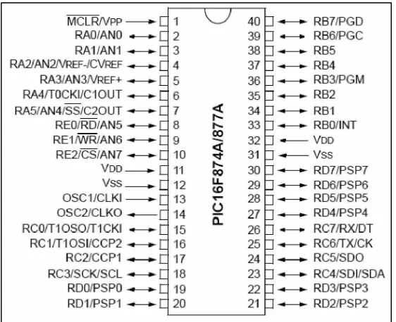
2.2.2 PIC 16F877A Pin-out
6 initializing various control registers within the chip. Note, in particular, that ports A and E become ANALOG INPUTS by default (on power up to reset), so they have to set up for digital I/O if required. PORTB is used for downloading the program to the chip flash ROM (RB6 and RB7), and RB0 and RB4-RB7 can generate an interrupt. Port C gives access to times and sera ports, while port D can be used as a slave port, which Port E providing the control pins for the function.
Figure 2.1 PIC16F877A Pin-out
The chips as two pairs of power pins (VDD= +5 V nominal VSS = 0 V), and either pair can be used. The chip can actually work down to about 2 v supply, for battery and power-saving operation.
7
2.3 Programming Compiler
For programming the PIC, microC compiler is used. It is a powerful, feature rich development tool for PICmicros. It is designed to provide the customer with the easiest possible solution for developing applications of embedded systems, without compromising performance or control. PIC and C fit together well, PIC is the most popular 8-bit chip in the world, used in a wide variety of applications, and C, prized for its efficiency, is the natural choice for developing embedded system.
MicroC provides a successful match featuring highly advanced IDE, ANSI compliant compiler, broad set of hardware libraries, comprehensive documentation, and plenty of ready-to-run examples. Compared to other compilers such as CCS compiler, SourceBoos and MPLAB, MicroC compiler is the easiest way for writing programming.
MikroC provides quickly develop and deploy complex applications:
a. Write your C source code using the built-in Code Editor (Code and Parameter Assistants, Syntax Highlighting, Auto Correct, Code Templates, and more. b. Use the included mikroC libraries to dramatically speed up the development:
data acquisition, memory, displays, conversions and communication. Practically all P12, P16, and P18 chips are supported.
c. Monitor your program structure, variables, and functions in the Code Explorer.
d. Generate commented, human-readable assembly, and standard HEX compatible with all programmers.
e. Inspect program flow and debug executable logic with the integrated Debugger. Get detailed reports and graphs: RAM and ROM map, code statistics, assembly listing and calling tree