VIBRATION ANALYSIS OF DYNAMIC MODELLING OF
GEAR PAIR IN MESH DUE TO TORQUE AND
LOAD ON THE SYSTEM
Wijianto
Mechanical Engineering Dept. Muhammadiyah University of Surakarta Jl. A. Yani Tromol Pos I Pabelan Kartasura Sukoharjo
E-mail : [email protected]
ABSTRACT
This paper presents dynamics modeling of gear pair in mesh. State space analysis and MATLAB operation are used to obtain natural frequencies and graphs of motion on the system. Torque load are applied to analysis numerical integration solution. The results are compared to the one without torque and load. The torque acts on pinion and the load acts on gear output. The natural frequencies of the gear pair in mesh system are calculated from the complex eigenvalues. The graphs of the gear angular velocity show that in star-up region, angular velocity increases with its rate velocity. It was vibrates with various amplitude. In steady state region, the gear angular has a constant average value. Applying the mesh stiffness variation affects in the changes of wave form and amplitude of the gear velocity vibration. The variable value of mesh stiffness causes vibration of the gear pair in mesh system. In addition, transmission error of the gear pair in mesh system tends to go into a constant value after periodically change. It is still vibrates in the gear system with the mesh stiffness variation.
Keywords: Dynamics modeling - gear pair – MATLAB - natural frequencies.
INTRODUCTION
Recent increase in using and operating of gear pair in the transmission system have led to intermittent noise and vibration problems in their gearing mechanism.
Dynamics modeling of gear pair in
mesh is very useful to improve
understanding of motion and vibration behavior of the system. The equation of motion can be arranged into the state space formulation base on vibration analysis and then with MATLAB operation supported by ODE solver (ODE23), graphs of motions and solution of problem of gear pair in mesh without damper can be
derived. The solution provides data of the gear motion which can be plotted into the graph of body velocity or angular velocity of both pinion and gear motion.
To improve the current techniques of
Gearbox vibration diagnosis and
monitoring, many researchers are
investigating the use of dynamic modeling of gearbox vibration to ascertain the effect of different types of gear train damage on the resultant gear case vibration (Randall, 1982). Modeling gear pair in mesh of this paper is based on the one developed by Du
(1987) and subsequently modified by
Dynamic model of multiple pairs of gears in mesh including friction has been modeled and detailed by Howard et all (2001) and Further report was made by
Rebbechi (1989) including friction and
geometry errors.
PROBLEM STATEMENT
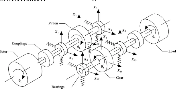
Developing model of gear pair in mesh is based on a single stage reduction gearbox where ratio of transmission is 1.75, and number of teeth for pinion is 36 and 63 for gear. In total, there are 16 degrees of freedom in the model and a schematic diagram as can be seen in figure 1.
Figure 1: Diagram of the 16 degree of freedom gear dynamic model
Main assumptions are made as follows:
- Neglect of resonances of the gear case.
- Applying input torque and attaching
load to the system.
- Shaft mass and inertia are lumped at
the bearings or the gears.
- Neglect of shaft transverse resonances.
- Ignore of shaft torsional stiffness
- Damper that are occur in the system
are neglected.
- Static transmission error effects are
very much smaller than the dynamic transmission error effects and so can be neglected.
EQUATION OF MOTION
The simplified gear pair in mesh is shown in Figure 2 below.
Figure 2: Coupling between the torsional and transverse motion in the gears and
shafts x1
kmb
x2 ks1
ks2 rg
rp Ig
Ip θ1
θ2 c
Where,
rs : base circle radius of input pinion
rg : base radius of output gear
ks : shaft/bearing transverse stiffness
kmb : linear translation tooth stiffness along
line contact c-c : line of contact.
The application of dynamic modeling to the vibration of simplified gear pair is reported in the following steps which are,
1.Derivation of the equation of motion for
the four degree of freedom system.
2.The state space formulation
3.The solution for natural frequencies from
the complex eigenvalues.
4.The solution of the motion of the gear
pair after applying the input torque to the input pinion and attaching a load to the output gear.
5.The solution of the motion of the gear
pair without damper.
6.Plotting the dynamic motion of gear
body velocity and gear torsional velocity for start-up and steady speed.
From the figure 2, the equation of motion of gear pair in mesh can be derived as 4 degree of freedom of motion. 4 equations can be obtained from this case, as following:
obtained from this case, as following:
0 written as
=
STATE SPACE FORMULATION FOR THE EQUATIONS OF MOTION
The matrix equation of motion will be solved by state space method, so the state space formulation should be constructed in order to obtain the natural frequencies and the solution of the motion of the gear pair.
−
NATURAL FREQUENCIES OF THE SYSTEM
The natural frequencies of the system can be obtain by the
Let the assumption of:
{ } { }
{ }
{ }
{ }
[ ]
{ }
{ }
Z[ ]
A{ }
Z e Z A e Ze Z V
e Z V
t t
t t
= = = =
λ λ
λ
λ λ
λ λ
(8)
Note:
λ{Z}=A{Z} is a standard eigenvalue
and eigenvector problem.
[A - Iλ]{Z}= 0
|A - Iλ| = 0 (9)
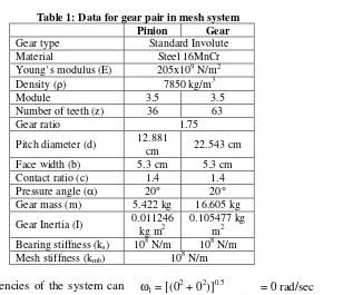
Applying initial condition and data for gear pair in mesh system below:
Table 1: Data for gear pair in mesh system
Pinion Gear
Gear type Standard Involute
Material Steel 16MnCr
Young’s modulus (E) 205x109 N/m2
Density (ρ) 7850 kg/m3
Module 3.5 3.5
Number of teeth (z) 36 63
Gear ratio 1.75
Pitch diameter (d) 12.881
cm 22.543 cm
Face width (b) 5.3 cm 5.3 cm
Contact ratio (c) 1.4 1.4
Pressure angle (α) 20° 20°
Gear mass (m) 5.422 kg 16.605 kg
Gear Inertia (I) 0.011246 kg m2
0.105477 kg m2 Bearing stiffness (ks) 108 N/m 108 N/m
Mesh stiffness (kmb) 108 N/m
The natural frequencies of the system can be obtained by substituting data in Table 1 above into the equation of |A - Iλ| = 0, which gives 8 complex eigenvalues. 8 complex eigenvalues are:
λ1 = 0.0 + 0.0i
λ2 = 0.0 - 0.0i
λ3 = 0.0 + 692.2i
λ4 = 0.0 - 692.2i
λ5 = 0.0 + 2467.1i
λ6 = 0.0 - 2467.1i
λ7 = -0.0 + 4316.6i
λ8 = -0.0 – 4316.6i
The natural frequencies thus become
ωi = [(Re(λi)2 + Im(λi)2]0.5
ω1 = [(02 + 02)]0.5 = 0 rad/sec
ω2 = [(02 + 692.22)]0.5 = 692.2 rad/sec
ω3 = [(02 + 2467.12)]0.5= 2467.1 rad/sec
ω4 = [(02 + 4316.62)]0.5= 4316.6 rad/sec
Or in the other shape of the natural frequencies in (Hertz) are
f1 = ω1 /2π = 0 Hz
f2 = ω2 /2π = 110.17 Hz
f3 = ω3 /2π = 392.65 Hz
f4 = ω4 /2π = 687.01 Hz
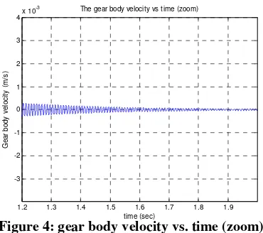
1.2 1.3 1.4 1.5 1.6 1.7 1.8 1.9
time (sec) The gear body velocity vs time (zoom)
0 0.2 0.4 0.6 0.8 1 1.2 1.4 1.6 1.8 2
time (sec)
The gear body velocity vs time (2 seconds)
0 0.2 0.4 0.6 0.8 1 1.2 1.4 1.6 1.8 2
time (sec)
The gear angular velocity vs time (2 seconds)
0.2 0.25 0.3 0.35 0.4 0.45
time (sec) The gear angular velocity vs time (zoom)
Applying an input torque to the input pinion, makes the matrix equation of motion becomes
− Torque data:
Torque input (Tin) : 75 Nm
The state space equation is solved by ODE Solver (ODE23) with MATLAB operation and applying initial conditions. The initial conditions are:
[V1, V2, V3, V4, V5, V6, V7, V8] =
Figure 3: gear body velocity vs. time
Figure 4: gear body velocity vs. time (zoom)
Moreover, solution of gear angular
velocity (
θ
2) can be displayed in theplotted graph in Figure 6 below, where is time spans from 0 to 2 sec.
Figure 5: gear angular velocity vs. time
0 0.2 0.4 0.6 0.8 1 1.2 1.4 1.6 1.8 2
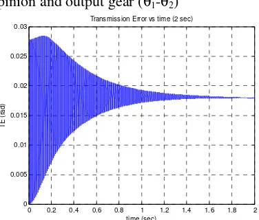
time (sec) Transmission Error vs time (2 sec)
0 0.5 1 1.5 2 2.5 3
shows the transmission error between input
pinion and output gear (θ1-θ2)
Figure 7 : Transmission Error of the gear system.
THE EFFECT OF MESH STIFFNESS VARIATION ON THE GEAR PAIR SYSTEM
Assuming that mess stiffness varies along the shaft rotation, which follows the equation of: (Lin & Parker, 2002, p.69)
)
2ka : peak-to-peak teeth stiffness
: (kmax-kmin)
Ω : mesh frequency (number of teeth
x angular velocity)
c : contact ratio
p : phasing angle
Mesh stiffness data
ko = 106 N/m
2ka = 6.105 N/m
Ω = z1 x ω1 = 36 x 231.5 =8834
rad/sec (=1326.4 Hz)
c = 1.4
p = 0
The 4 cycles of mesh stiffness with mesh frequency of 1326.4 Hz is shown in figure 8 below
Figure 8: Mesh stiffness variation
DISCUSSION
Firstly, the natural frequencies of the gear pair in mesh system are found from the complex eigenvalues. When the damping isn’t included into the system, the complex eigenvalues only have imaginer components.
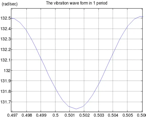
angular speed will reach a constant value of 132.3 rad/s. The interesting thing is in what frequency the angular velocity vibrates before it decays away. The question can be answer by check the period of the wave form. As can be seen in
Figure 9, the period (T) is (0.506 sec – 0.497 sec) = 0.009 sec. Thus the frequency
is (1/0.009) Hz ≅ 110 Hz which very close
to the second natural frequency (=110.17 Hz) (the first natural frequency is 0 Hz).
Figure 9: The angular velocity vibration wave form in 1 period.
Moreover, from figures above shows that although the damping is not included into the system, the vibration amplitude tends to decay away. It may possibly because the effect of applying the load in output gear. In the start-up region, the output torque increases proportionally to the square of gear angular velocity. The increasing of output torque also absorbs the energy from the system thus it acts as a damping.
Further, applying mesh stiffness
variation into the gear pair in mesh system affects to the vibration amplitude, transient period time and frequency.
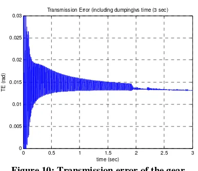
Finally, the solution also provides data that can be describe the transmission error
between input pinion and output gear. Figure 10 shows the transmission error of the gear pair system before and after applying a damping and after uses the variable value of mesh stiffness. The
transmission error in the two-first
condition reveal that at start-up region the transmission error has a maximum value after that it decrease then tend to converge into constant value. However, in mesh
stiffness variation condition, the
transmission periodically changes in steady speed region.
0.497 0.498 0.499 0.5 0.501 0.502 0.503 0.504 0.505 0.506 131.7
131.8 131.9 132 132.1 132.2 132.3 132.4 132.5
0 0.5 1 1.5 2 2.5 3 0
0.005 0.01 0.015 0.02 0.025 0.03
T
E
(
ra
d
)
time (sec)
Transmission Error (including dumping)vs time (3 sec)
Figure 10: Transmission error of the gear system in variable mesh stiffness.
CONCLUSION
1. The natural frequencies of the gear
pair in mesh system are found from the complex eigenvalues.
2. In start-up region the gear angular
velocity increases into its rate velocity,
it also vibrates with various
amplitudes. Then in steady state region, the gear angular velocity has a constant average value but still vibrates. The vibration amplitude tends to decay away. Also, that vibration has a frequency which is very close to the second natural frequency.
3. Applying the mesh stiffness variation
affects in the changes of wave form and amplitude of the gear velocity vibration. And the variable value of mesh stiffness causes vibration in the gear pair in mesh system.
4. Transmission error of the gear pair in
mesh system tend to go into a constant value after periodically change is decay away. But, it still vibrates in the gear system with the mesh stiffness variation.
REFERENCES
Du S (2001), Dynamic modelling and simulation of gear transmission error for gearbox
vibration analysis, Ph.D. Thesis
Howard I, Jia S, and Wang J 2001, The dynamic modeling of spur gear in mesh including
friction and crack, Journal of Mechanical and signal processing, retrieved may 2006
from http://www Idealibrary.com
Howard I (2006), Vibration: lecture note, Department of Mechanical Engineering Curtin
University of Technology
Jia s, Howard I 2005, Comparison of localized spalling and crack damage from dynamics
modeling of spur gear vibration, Journal of Mechanical and signal processing, retrieved may 2006 from http://www sciencedirect.com
Lin, J & Parker, R.G. 2002, ‘Mesh stiffness variation instabilities in two-stage gear
system’, Journal of vibration and acoustics, vol. 124, pp. 68-76.
Metal Suppliers Online: Material Property Data, retrieved March 21, 2006 from
http://www.suppliersonline.com/propertypages/8620.asp
Randall R.B 1982, A new method of modeling gear faults, Journal of Mechanical Design 104 pp. 259–267.