ISSN 1990-9233
© IDOSI Publications, 2013
DOI: 10.5829/idosi.mejsr.2013.18.6.12486
Corresponding Author: Ali Ahmad Milad, Department of Computer System and Communication,
Faculty of Information and Communication Technology, Universiti Teknikal Malaysia Melaka, Hanngtuha Jaya, 76100 Durian Tunggal, Melaka. Malaysia.
Reverse Direction Transmission in Wireless Networks: Review
Ali Ahmad Milad, Zul Azri Bin Muhamad Noh, Abdul Samad Shibghatullah and Mustafa Almahdi Algaet
Department of Computer System and Communication, Faculty of Information and Communication Technology,
Universiti Teknikal Malaysia Melaka, Hanngtuha Jaya, 76100 Durian Tunggal, Melaka, Malaysia
Abstract:Reverse direction mechanism is a promising significant development that may lead to promoting the accuracy of TXOP. The transfer, in conventional TXOP operation, is one way direction out of the station which holds the TXOP and which is not applied to some network services using two lane traffic namely VoIP and on-line gaming. Therefore, the conventional TXOP operation enhances only the forward direction transfer, but not the reverse direction transfer. Moreover, reverse direction mechanism makes it possible for the holder of TXOP to reserve unused TXOP time for its receivers which may improve the channel utilization as well as the performance of reverse direction traffic flows. It is well-known that the reverse direction transfer scheme aims mainly to improve the effectiveness and that plays a key role in reducing the overhead and increasing the system throughput. Thus, this paper provides an overview of a research progress in reverse direction transmission scheme over high speed wireless LANs. Moreover, it addresses the reverse direction mechanism that has been proposed for the next generation wireless networks and the ones adopted by IEEE 802.11n standard. Furthermore, it stresses the reverse issues that require to be dealt with in order to bring further progress to the reverse direction transmission.
Key words: Reverse direction Wireless LANs IEEE802.11 TXOP
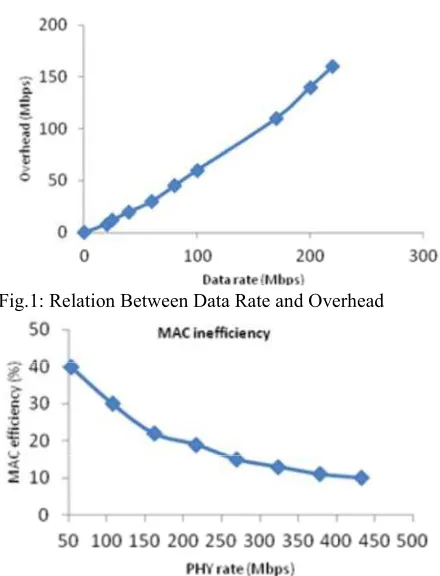
INTRODUCTION throughput, thus, causing an increase in the overhead. This section of the paper introduces informational data rate and the overhead at the MAC layer [6].
background of the IEEE802.11 throughput and delay limits To achieve a wide performance enhancement or and it provides a detailed discussion about the improvement, it is important to find out the major problem improvements that have been used over high speed which causes MAC inefficiency as displayed in Figure 2 wireless LANs. [7]. The theoretic throughput higher limit and the theoretic IEEE802.11 Delay and Throughput Limits: Wireless The presence of such limitations assures the LANs based on IEEE 802.11 increases everywhere to augmentation of the data rate without diminishing the support many applications using TCP, UDP, HDTV and overhead [8].
VOIP. In IEEE802.11a the data rate reaches 54Mbps,
IEEE802.11b reaches 11Mbps and the physical data rate in Enhancements the Performance of MAC Layer:During IEEE802.11n may reaches up to 600Mbps to get high transmission, the frame in Distributed Coordination efficiency at MAC layer [1-5]. The idea behind this is that Function (DCF) scheme provides some overheads that the increase in the physical rate can result into increasing can be clarified as: Distributed Inter-Frame Space (DIFS), the transmission at MAC link and increasing the backoff iming, PHY header and Short Inter-Frame Space Figure 1 describes the relation between the increasing
Fig.1: Relation Between Data Rate and Overhead unit (A-MSDU) and aggregate MAC protocol data unit
Fig.2: Relation Between Data Rate and MAC Efficiency 802.11n specifies is the bidirectional data transfer method (SIFS). All of these types of overheads minimize the time This characteristic allows the transfer of data frames and this can be an influential factor at performance of including aggregates in both directions in one TXOP. MAC layer [9]. So, to get high and good performance at Currently, allocating the sender STA with a TXOP may MAC layer, it is necessary to mitigate the overheads. inform surrounding STAs about the duration of the Many researchers have introduced the enhancements of wireless medium engagement. The results this MAC layer. In IEEE 802.11e,the data frames are sent in approximation of channel provides, however, cannot sequential separate ways, adding to that,these data always be accurate and the transfer failure is often sooner. frames were acknowledged by block acknowledgment In other cases, contended STAs, therefore, assume that (BA) after sending block acknowledgment request from the channel is still occupied. Moreover, with reverse the sender (BAR) [10, 11]. Besides, IEEE 802.11n direction, any available packets addressed to the sender (next generation wireless LANs) provides high for the remaining TXOP time are allowed to be sent by the throughput mechanism and may reach more than 100 initial receiver STA. This, in particular, suits TCP well as Mbps [5].There are two possible methods that can be it permits a TCP link to piggyback TCP ACK collection achieved to enhance the performance of next generation onto TCP data transfer. The long network allocation wireless LANs: the first one aims to increase the physical vector (long-NAV) is another progress that develops data rate in the PHY layer and the second one aims to scheduling as long as the station that includes a TXOP increase the efficiency of the MAC layer [12]. may set up a longer NAV value for the intention to save Enhancements of IEEE 802.11n:The IEEE 802.11Working phased coexistence operation (PCO) which mainly aims to Group adopts the IEEE 802.11n, which is a modified protect stations either through 20 MHz or 40 MHz channel version of higher throughput and higher speed spectrum at the same time. Lastly, the reduced IFS (RIFS) improvement. The main goal of IEEE 802.11n is to provide is suggested to permit a time interval of 2 µs between a higher throughput rather than higher data rates along multiple PPDUs, which is much shorter than SIFS as with PHY and improvements of medium access control identified in the legacy standards.
(MAC) [13]. Moreover, IEEE 802.11n provides many enhancements to reduce the overhead at MAC layer, such as: frame aggregation, Block acknowledgment (BA) and reverse direction transmission (piggybacking) [14]. The Improvements of next generation wireless LANs IEEE802.11n will be discussed in details especially in more concern with the reverse direction transmission.
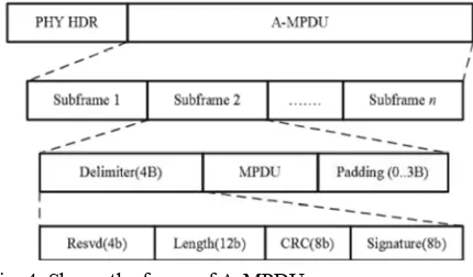
Frame Aggregation:Frame aggregation is defined as a function which allows combining several frames into a single large frame for transfer. It is carried out by using two available methods: aggregate MAC protocol service (A-MPDU). Moreover, an MSDU is mainly distinguished from an MPDU in that whereas the former is correspondent to the information that is imported to or exported from the upper part of the MAC sub layer, respectively, from or to the higher layers, the latter depends on the information transferred by the lower part of the MAC from or to the PHY. Aggregate exchange sequences are facilitated by a protocol acknowledging multiple MPDUs with a single block ACK. This is made as a response to a block acknowledgment request (BAR). Another key to achieving such improvement is that the over a single TXOP. This is called a reverse direction.
Fig. 3: Shows the frame of A-MSDU
A-MSDU Aggregation: The A-MSDU (or MSDU Fig. 4: Shows the frame of A-MPDU aggregation) objective is mainly to permit sending
multiple MSDUs to the same receiver concatenated in a corrupted. This case is dealt with in [15], where single MPDU. Absolutely, this leads to enhancing the further frame structures or optimum frame sizes have effectiveness of the MAC layer, mainly when many small been suggested to achieve accuracy under noisy MSDUs, such as TCP acknowledgments are included. channels.
This function of enhancement for A-MSDU within the
802.11n is proved to be compulsory at the receiver’s A-MPDU Aggregation: The major aim of the concept of side. To form an A-MSDU, a layer at the top of the A-MPDU aggregation is to connect multiple MPDU sub MAC receives and buffers multiple packets (MSDUs). frames with a single leading PHY header. The only aspect The A-MSDU is fulfilled in one of these two cases: in which it differs from A-MSDU aggregation is the having the size of the waiting packets reach the maximal function of A-MPDU since it commences after the A-MSDU threshold or in the second case when the MAC header encapsulation process. Because of this, the maximal delay of the oldest packet reaches a pre-assigned A-MSDU restriction of aggregating frames with matching value. Moreover, its maximum length can be either 3839 or TIDs is not considered as a factor with A-MPDUs. 7935 bytes; this is 256 bytes shorter than the maximum However, it is necessary to deal with all the MPDUs PHY PSDU length (4095 or 8191 bytes, respectively), as within an A-MPDU using the same receiver address. the expected space is preserved for future status or Besides, the luck of waiting/holding time needed in controlling information. The size can be noticed in the forming an A-MPDU makes the number of MPDUs high throughput (HT) capabilities element which is which should be added totally dependent on the advertised from an HT STA in order to affirm its HT number of packets which already exist in the transmission status. Although the maximal delay can be set to an queue. Furthermore, the maximum length obtained by an independent value for every AC, it is usually set to 1 µs A-MPDU (the maximum length of the PSDU probably to for all ACs. When constructing an A-MSDU, certain be received) is 65,535 bytes. However, it is possible to be limitations can be detected: further limited depending on the capabilities of the STA The same TID value must be acquired by all MSDUs. maxim number of sub frames that it may acquire is 64 and Lifetime of the A-MSDU should be appropriate to this is due to the reason that a block ACK bitmap field is the maximum lifetime of its constituent elements. 128 bytes in length, where mapping each frame is The destination address (DA) and sender address performed using two bytes. It is also important to notice (SA) parameter values in the sub frame header must that these two bytes are needed for acknowledging up to correspond to the same receiver address (RA) and 16 fragments. However, since the A-MPDUs prevent transmitter address (TA) in the MAC header. fragmentation, these additional bits become excessive. Broadcasting or multicasting, therefore, is prevented. compressed block ACK with a bitmap field of eight bytes However, the main weakness of employing A- MSDU is long. Lastly, the size of each subframe is confined to 4095 represented by the under error-prone channels. bytes as the length of a PPDU cannot surpass the 5.46-ms Furthermore, the entire A-MSDU must be retransferred, time limit; this can spring out of the maximum length by combining all MSDUs into a single MPDU with a divided by the lowest PHY rate, which is 6 Mb/s and is single sequence number, for any sub frames that are the highest duration of an MPDU in 802.11a [16].
existing in the HT capabilities element. Moreover, the
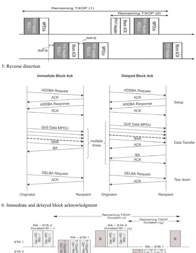
Block Acknowledgment: A Block ACK method is a Reverse Direction Grant (RDG) in the RDG/More PLCP proposed in the IEEE802.11e specification [20]; in (BTA) protocol data unit (PPDU) field of the HT Control field in block transmission and acknowledgment scheme and the MAC frame as illustrated in Figure 7. This bit is therefore a block of data frames send it to the destination adopted by the RD initiator to grant access (RDG) to the in sequence and between each one and the data frame RD responder and by the RD responder to prove if it can there is a SIFS period of time. After sending the block of send more frames immediately after the one it has just data, the sender starts sending the (BAR) block received (More PPDU)[21].
acknowledgment requestto ask about frame which has
been received by the receiver. Then, the (BA) block Reverse Direction (RD) Exchange Sequence: acknowledgment is sent back to the sender including An RD Exchange Sequence Includes: information about the frame received as illustrated in
Figure 6. When the block acknowledgement is received The transfer of the PPDU by the TXOP holder correctly, the sender is supposed to delay the DIFS and including an RD grant (the RDG PPDU) as indicated back off mechanisms earlier than sensing the channel and by the PPDU consists of one or more high all other stations should wait until the block throughput control (+HTC) MPDUs in which the acknowledgment transmission finishes. If many stations RDG/More PPDU subfield is put into 1. The STA have started transmitting the data with BAR at the same transmitting this PPDU is called the RD initiator. The time, the collections will occur. Moreover, when each process of carrying out the rules for an RD initiator is station sends the data with BAR, the receiver should wait performed only during a single RD exchange to detect the collision first and then send the block sequence (e.g. after the transfer of an RDG PPDU till
acknowledgment. the end of the last PPDU in the RD exchange
Reverse Direction: Two types of stations are The transfer of one or more PPDUs (the RD response identified in reverse direction operation: RD initiator burst) by the STA is dealt with in the MPDUs of the and RD responder. RD initiator which is the station RDG PPDU. The first (or only) PPDU of the RD holding the TXOP that permits sending the Reverse response burst includes at most one immediate Block Direction Grant (RDG) to the RD responder. Furthermore, ACK or ACK response frame this process is called RDG is marked in the 802.11n header and sent together piggybacking. The last (or only) PPDU of the RD with the data frame to the RD responder. When receiving response burst includes any MPDUs requiring an the data frame with RDG, the RD responder responds with immediate Block ACK or ACK response. The RD RDG acknowledgement, mainly if it has data that needs to responder is the STA that transfers the RD response be sent or without RDG when no data is available to be burst.Furthermore, It is only during a single RD sent to the RD initiator. Then, the RD initiator needs to exchange sequence that the rules for an RD wait for the transfer from the RD responder [17-19], responder can be applied, i.e. following the reception when the acknowledgement is marked with RDG. of an RDG PPDU and up to the transfer of the PPDU
Figure 5. by the RD responder in which the RDG/More PPDU
Reverse Direction Transmission Approaches: The The transfer of the PPDU by the RD initiator 802.11n RD protocol mainly aims to accurately exchange containing an immediate Block ACK or ACK MPDU the data between two 802.11 devices during a TXOP by (the RD initiator final PPDU), If so needed by the last restricting the necessity for either device to have access PPDU of the RD response burst.
to a further data exchange. Before the RED protocol, each uni-directional data transfer needs the initiating station to
attract (and possibly reserve time on) a contention-based NOTE: The RD initiator may contain multiple RD RF medium. With RD, the other stations are essentially exchange sequences within a single TXOP. Each RD allowed to send information back once the transmitting exchange sequence within a single TXOP that can be station has attained a TXOP. Therefore, two roles need dealt with by different recipient and it is probable that any be identified: RD initiator and RD responder. The RD single recipient includes more than one RDG within a initiator sends its permission to the RD responder due to single TXOP.
sequence).
Fig. 5: Reverse direction
Fig. 6: Immediate and delayed block acknowledgment
Fig. 7: Revere direction exchange
Rules for RD Initiator: An RDG can exist provided that the MPDU which carries the grant or even each MPDU carrying the grant in an A-MPDU does not correspond to one of these conditions listed below:
The QoS data MPDU with the ACK Policy field is carried out at any value except power save multi poll (PSMP) ACK (i.e. including Implicit Block ACK Request), or
The Block ACK Request is relevant to the HT-immediate Block ACK agreement, or
The MPDU does not require straight response (e.g. Block ACK under an HT-immediate Block ACK agreement, or Action No ACK).
Within a PSMP sequence, an RDG will not be dealt with. NOTE 1: These regulations are meant to guarantee that an RDG is conveyed in the PPDU that requires neither an immediate response nor an immediate Block ACK or ACK response.
NOTE 2: It is not necessary that the RD initiator ought to treat the RD Responder field of a potential responder before taking the decision to send the PPDU to that STA in which the RDG/More PPDU subfield is put into 1. NOTE 3: The RD initiator is needed to identify the +HTC Support field of a potential responder before taking the decision of sending the PPDU to that STA in which the RDG/More PPDU subfield is put into 1, Table 1.
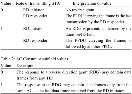
Transfer of a +HTC frame by an RD initiator with the RDG/More PPDU subfield put into 1 (either transferred as a non-A-MPDU frame or within an A-MPDU) proves that the duration mentioned by the Duration/ID field is valid for the RD response burst and RD initiator final PPDU (if present).
The RD initiator that sets the RDG/More PPDU field put into 1 in a +HTC frame will have the access category (AC) constraint subfield to 1 in that frame if the TXOP is accomplished due to the EDCA channel access mechanism and will otherwise put it into0, as illustrated in Table 2.
The RD initiator will not exchange a +HTC frame with the RDG/More PPDU subfield put into 1 that needs a response MPDU except these below:
ACK
Compressed Block ACK
Table 1: RDG/More PPDU subfield values
Value Role of transmitting STA Interpretation of value
0 RD initiator No reverse grant
RD responder The PPDU carrying the frame is the last transmission by the RD responder
1 RD initiator An RDG is present, as defined by the duration/ID field
RD responder The PPDU carrying the frames is followed by another PPDU
Table 2: AC Constraint subfield values
Value Description
0 The response to a reverse direction grant (RDG) may contain data frames from any TID.
1 The response to an RDG may contain data frames only from the same AC as the last data frame received from the RD initiator.
Subject to TXOP restrictions, after transferring an RDG PPDU, the RD initiator can exchange its next PPDU as follows:
Normal Continuation: The RD initiator can transfer its next PPDU a minimum of a SIFS after getting a response PPDU that satisfies one of the above conditions:
It should include one or more accurately received +HTC frames with the RDG/More PPDU subfield put into0, or
It should include one or more accurately received frames that are able to carry the HT Control field but they should not consist of an HT Control field, or It should include a correctly received frame that needs a straight response.
Error Recovery: When the carrier sense (CS) mechanism proves that the medium is idle at the TxPIFS slot boundary, the RD initiator can transfer its next PPDU (this transfer is a process of the current TXOP).
NOTE 1: The RD initiator is responsible for recovering Error of the RDG mechanism
NOTE 2: If the response is corrupted after exchanging a PPDU including an RDG, therefore the state of the RDG/More PPDU subfield is unknown and the RD initiator of the RD transmission is prevented to exchange after a SIFS interval. Transfer may happen at a PIFS interval after reassertion of (CS).
The STA that exchanges a QoS +CF-ACK data frame The RD responder shall transfer data frames of only can also contain an RDG in that frame in condition that: the same AC, as the last frame is received from the RD It is a non-A-MPDU frame and 1.Moreover, for a Block ACK Request or Block ACK The target of the +CF-ACK is equal to the Address 1 frame, the AC is identified when treating the TID field. For field of the frame. a management frame, the AC is AC_VO. The RD initiator NOTE: The RD initiator may exchange a CF-End frame RDG/More PPDU subfield put into 1 from which the AC following to the rules for TXOP truncation and according is difficult to be figured out. Furthermore, the RD RD transfer sequences. An RD responder never responder can exchange data frames of any TID, if the AC
exchanges a CF-End. Constraint subfield is put into 0.
Rules for RD Responder: After the reception of the RDG transfer any frames with an Address 1 field that is not PPDU, an RD responder will transfer the initial PPDU of comparable to the MAC address of the RD initiator. the RD response burst a SIFS. PPDUs in a response burst When an RDG PPDU also requires an immediate are separated by SIFS or RIFS. Block ACK response, the Block ACK response frame will NOTE:The transfer of a response by the RD responder process is called piggybacking.
does not provide a new channel access but a progress of An HT Control field treating the RDG/More PPDU the RD initiator’s TXOP. When responding to an RDG, an subfield put into 1 will exist in every MPDU within the RD responder forgets about the NAV. PPDU and be able to deal with the HT Control field when The Recipient of an RDG Can Reduce the RDG By: The last PPDU of a response burst will contain the
Denying exchanging any frames coming after the existed in that PPDU.
RDG PPDU,when no response is otherwise needed,or The RD responder will not put the RDG/More PPDU Exchanging a control response frame with the subfield into 1 in any MPDU in a PPDU that has an RDG/More PPDU subfield put into 0, or MPDU that needs a straight response.
Exchanging a control response frame that includes no
HT Control field. NOTE: The RD responder has to wait for either another An RD responder may transmit a +CF-ACK non-A- RD responder exchanges a PPDU that estimates a transfer MPDU frame in response to a non-A-MPDU QoS by the RD initiator after SIFS and such transfer is Data +HTC MPDU that has the ACK Policy field set to unnoticed.
Normal ACK and the RDG/More PPDU subfield set to 1. The RD responder will not be able to transfer any The RD responder will make sure that its PPDU more PPDUs within the current response burst, after transfer(s) and any expected responses fit completely exchanging the PPDU containing one or more +HTC within the remaining TXOP duration, as revealed in the MPDUs in which the RDG/More PPDU subfield is put Duration/ID field of MPDUs within the RDG PPDU. into 0.
An RD responder will not transfer an MPDU (either
individually or aggregated within an A-MPDU), except NOTE: When the RD-capable STA that is not the TXOP one of these mentioned below: holder receives the PPDU that does not have an
ACK response in comparison with the STA that is not
RD-Compressed Block ACK capable.
Compressed Block ACK Request (BAR) In [23] a new scheme of simple reverse direction data
QoS data transfer that is capable of achieving sufficient reduction
Management of the bottleneck overhead and permission of the data initiator when the AC Constraint subfield is put into
will not be able to exchange a +HTC MPDU with the
During an RDG, the RD responder will not be able to
be included in the first PPDU of the response and this
a PPDU is not the final PPDU of a response burst. RDG/More PPDU subfield put into 0 in all +HTC MPDUs
RDG or its own TXOP before retrying the transfer, if the
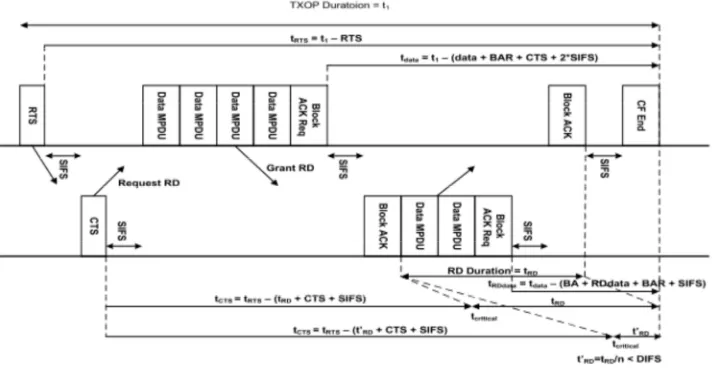
Fig. 8: Data service in RD protocol
packets flow in both directions was suggested. The The RD Protocol Exchange is Summarized as Follows: Initiator sends the RTS which contains NAV duration of
TXOP. According to the receipt of RTS, the responder The RD initiator (the TXOP holder) sends the PPDU checks whether it has any packet to send to the initiator. which includes the RDG and that needs an immediate And when it has, it determines the duration required for response.
the reverse direction data transfer. Under the normal The RD responder will respond with one or more conditions, the CTS from responder must include the PPDUs. The first or only PPDU will include one or duration in the RTS minus, the sum of CTS and SIFS more ACKs or Block ACK frames (piggyback). duration. Regarding the reverse direction, the responder The last or only PPDU exchanged by the RD also subtracts the value of reverse data duration from the responder in the burst will include any packets that received duration in the RTS and sends the CTS with need a straight ACK or Block ACK response. The modified duration to the initiator. The initiator checks the last PPDU will have the RDP/More PPDU subfield. duration in the CTS to insure the equality of the difference
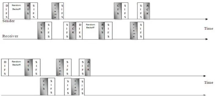
existing between the duration in the RTS and the CTS in Bidirectional Transmission:
one hand and the CTS and SIFS duration. However, when Piggyback Scheme: When the data packets are it is not equal, then the initiator can realise that responder transferred in duplex directions from part A to part B and has packet to exchange. Furthermore, as displayed in the data arrives at B, instead of sending a control frame Fig. 8 below, the initiator can provide use to the responder from B to A, receiver B waits until the network layer at B by the piggybacking data MPDU or BA Request (BAR) sends the next packet to A and the acknowledgment is MPDU, when this duration is less than the remaining attached in the data frame from B to A using the field of
TXOP. acknowledgment in the data frame header. Therefore, the
In [24], the authors identified the value of reverse acknowledgment gets a free ride in the data frame and this direction data flow characteristic of the emerging IEEE technique is known as piggybacking. One of the most 802.11n WLAN standard and studied the benefit of using well-known advantages of piggyback scheme is it in terms of its performance and clarified the way this improving the efficiency, which plays the role in reducing merit springs out. The authors also deduced that RDF the overhead and increasing the system throughput. diminishes the number of contentions by a factor of
1.5 to 2 and thus decreases the number of collisions Overview of Piggyback: When the receiver station has a within WLAN during EDCA phase. Besides, it diminishes frame to the sender station and allows sending the data the MAC overhead associated with contention by frame with ACK to the sender, this process is called a
Fig. 9: The overhead with/without the piggyback scheme
ride in the data frame and takes few bits and this is a In IEEE 802.11 WLAN data frame can increase the distinct ACK. Therefore, each frame requires an ACK channel efficiency in a wireless. But the piggyback will header and data frame (checksum). This means that the decrease the channel efficiency for frame transmission piggyback merely relies on the receiver since the fewer the delay. In Global control information the stations have a frames are sent, the fewer the frames that arrive and this is low transmission rate and in control frames. So the dependent the way the receiver is organized. However, piggyback deals with the problem concerning the low the emergence of the piggyback scheme has posed some physical transmission rate and evaluation of the effect of cases of complexity. For example, the question of how this problem with respect to the average frame long the data link layer is supposed to wait until the transmission delay and the channel utilization. Therefore, packet is transmitted to piggyback the ACK is still a the purpose of proposing the delay-based piggyback posing a complex case. As far as we know, the link layer scheme by the authors was to mitigate the piggyback usually waits for a certain period of time and if this waiting problem [26]. And as revealed by the same authors, the period consumed by the data link layer is longer than the piggyback led to decreasing the channel efficiency while sender timeout period, it is expected that the frame will be increasing the transmission delay for one station with low retransmitted. Therefore, it is assumed that the data link physical transmission rate were present.
layer must wait for fixed time like Ad hoc scheme such as [27] investigated the piggyback scheme when the number of milliseconds. On the other hand, one of the data frame was transmitted in two cases for the station. If benefits of the piggyback is that the piggyback frame the frame was corrupted, so whole the process would re-does not need to rivalry the channel again in a case when start, or the data frame would be received successfully. the receiver has a frame to send to the sender. This is The researcher also showed that the wireless station turn because it does not need to be in the front of the queue on piggyback scheme when the packet is less than but the nearest frame to the destination at the sender. In 1100bytes. Moreover, the throughput is very low because [25] the researcher shows the overhead with/without the overhead is high and the data rate is better than the piggyback mechanism in case when the frame belong to piggyback because the time missed in retransmitting the the receiver is sent to the sender after receiving a frame as “data+Acknowlegment” frames is reduced.
[29] defined the piggyback problem that when the piggyback can be used to improve the bandwidth control frame is piggybacked the channel efficiency is efficiency, but it is possible to increase the delay of decreased and at the same time, the station has a low channel access. The bandwidth efficiency with piggyback physical rate. The researchers also showed that and requests can be saturated more quickly with the increased evaluated the channel utilization with and without the number of SSs than that without piggyback requests. piggyback frame and they proved that utilization of
channel means the ratio of the total frame transmission Related Study (Types of ACKs):
time to the super frame length. So they solved the Cumulative Acknowledgment: This refers to the stance in piggyback problem as the low physical rate by calculating which each acknowledgment confirms correct reception of the delay of the piggyback scheme and proposed the all bytes up to the ACK number.
delay base piggyback scheme and found that the
piggyback was decreasing the channel efficiency while Acknowledgment Only Segment and Piggybacking: increasing the frame transmission delay even in one Based on this type of acknowledgments, the indication of station physical rate. However, when the physical the ACK is figured out through an ACK field in the TCP transmission rate increases. In this method channel header. Therefore, in acknowledging that the bytes have efficiency and the delay efficiency are also increased. been received correctly, the receiver can also create or Therefore, if the piggyback practices well, the channel develop an ACK segment which carries only the header efficiency and the delay transmission will increase. that contains the ACK number. Another way of But the proposed algorithm is expected to decrease acknowledging the correct received bytes is sending the the average frame transmission delay and the channel ACK in data segment and when the ACK travels in this utilization is estimated to be about 24% and 25%, data segment, the process is usually known as respectively if there is one station which has low a piggybacking.
physical transmission rate.
[30] Showed that the piggyback mechanism reduces Delayed Acknowledgment: This feature indicates that the the delay for uplink and downlink packets and the packets TCP receiver has two different options: either it generates loss probability for uplink traffic and downlink traffic for the ACK and receives a segment or it delays / postpones the case of backoff method and piggyback method. For the ACK for a short period of time. In the case of downlink data, packets do not occur for piggyback following the second option which is delaying the ACK, method and the loss packets of downlink data packet for the receiver will be able to acknowledge two segments at the backoff is not small. Moreover, the piggyback method one time and reduces the ACK traffic. However, in case of reduces the energy consumption significantly and there a long time-delay of the ACK can cause a timeout and are no losses of downlink data packets. retransmission at the sender. Therefore, the recommended [31] Investigated QoS data frames and their related span of time during which the receiver delays the ACK usage rules to increase the channel efficiency. A CF-boll should not be more than 500ms.
used to grant the channel to QSTA and piggybacked in
QoS the data frame to increase the channel efficiency. Duplicate ACK: This feature points at the case in which However, the channel efficiency may be decreased by CF- the segment gets lost in traffic and the segment following boll piggyback problem when QSTA associated in QBSS it arrives safely at the receiver. It is possible for the uses the low physical rate. The CF-boll piggyback scheme receiver to receive the data in a sequent series or number varies between 24 and 36Mbps depending on the traffic just beyond the range expected to be received. In such a
load. case, the receiver performs the processes of buffering the
REFERENCES 12. Lee, T.H., Y.W. Kuo, Y.W. Huang and Y.H. Liu, 1. Abichar, Z. and J. Chang, 2013. Group-based medium acknowledgments? In: Vehicular Technology access control for ieee 802.11 n wireless lans. Conference (VTC 2010-Spring), 2010 IEEE 71st. IEEE: 2. Akhmetov, D., 2006. 802.11 n: Performance results of pp: 1-5.
reverse direction data flow. In: Personal, Indoor and 13. Li, T., Q. Ni, D. Malone, D. Leith, Y. Xiao and Mobile Radio Communications, 2006 IEEE 17th T. Turletti, 2009. Aggregation with fragment International Symposium on. IEEE: pp: 1-3. retransmission for very high-speed wlans. 3. Anwar, S., O. Mohamed, S. Shamala and A.H. Nor, IEEE/ACM Transactions on Networking (TON),
Frame aggregation in wireless networks: Techniques 17(2): 591-604.
and issues. IETE Technical Review, pp: 28. 14. Li, T., Q. Ni, T. Turletti and Y. Xiao, 2005. Performance 4. Committee, S., 2005. Wireless lan medium access analysis of the ieee 802.11 e block ack scheme in a control (mac) and physical layer (phy) specifications: noisy channel. In: Broadband Networks, 2005. Amendment 8: Medium access control (mac) quality BroadNets 2005. 2nd International Conference on. of service enhancements. IEEE Computer Society. IEEE: pp: 511-517.
5. Group, I.W., 2006. Ieee p802. 11n/d1. 0 draft 15. Lim, W.S. and Y.J. Suh, 2010. Achieving per-station amendment to standard for information technology- fairness in ieee 802.11 wireless lans. In: World of telecommunications and information exchange Wireless Mobile and Multimedia Networks between systems-local and metropolitan networks- (WoWMoM), 2010 IEEE International Symposium on specific requirements-part 11: Wireless lan medium a. IEEE: pp: 1-9.
access control (mac) and physical layer (phy) 16. Lin, Y. and V.W. Wong, 2006. Wsn01-1: Frame specifications: Enhancements for higher throughput. aggregation and optimal frame size adaptation for ieee Local and Metropolitan Networks, Specific 802.11 n wlans. In: Global Telecommunications Requirements, Part, pp: 11. Conference, 2006. GLOBECOM'06. IEEE. IEEE: pp: 6. Hassan, M. and R. Jain, 2004. High performance 1-6.
tcp/ip networking. Pearson Prentice Hall. 17. Milad, A.A., Z.A.B.M. Noh, A.S. Shibghatullah, S. 7. He, J., K. Yang, K. Guild and H.H. Chen, 2008. Sahib, R. Ahmad and M.A. Algaet, 2013. On bandwidth request mechanism with piggyback Transmission control protocol performance in fixed ieee 802.16 networks. Wireless comparison using piggyback scheme in wlans. Communications, IEEE Transactions on, 7(12): Journal of Computer Science, 9(8): 967.
5238-5243. 18. Mujtaba, S.A., 2005. Tgn sync proposal technical
8. Ketchum, J., S. Nanda, R. Walton, S. Howard, M. specification. IEEE 802.11-04/0889r7.
Wallace, B. Bjerke, I. Medvedev, S. Abraham, A. 19. Ozdemir, M., D. Gu, A.B. McDonald and J. Zhang, Meylan and S. Surineni, 2005. System description and 2006. Enhancing mac performance with a reverse operating principles for high throughput direction protocol for high-capacity wireless lans. In: enhancements to 802.11. QUALCOMM Inc. Vehicular Technology Conference, 2006. VTC-2006 9. Lee, H.J. and J.H. Kim, 2006. A optimal cf-poll Fall. 2006 IEEE 64th. IEEE: pp: 1-5.
piggyback scheme in ieee 802.11 e hcca. In: 20. Park, J.S., T.O. Kim, K.J. Kim and B.D. Choi, 2009. Advanced Communication Technology, 2006. ICACT Performance analysis of ieee 802.15. 4 non-beacon 2006. The 8th International Conference. IEEE: pp: 6. mode where downlink data packets are transmitted by 10. Lee, H.J., J.H. Kim and S.H. Cho, 2007. A delay-based piggyback method. In: Communications Workshops, piggyback scheme in ieee 802.11. In: Wireless 2009. ICC Workshops 2009. IEEE International Communications and Networking Conference, 2007. Conference on. IEEE: pp: 1-6.
WCNC 2007. IEEE. IEEE: pp: 447-451. 21. Pries, R., D. Staehle and D. Marsico, 2007. 11. Lee, H.J., J.H. Kim and S. Cho, 2007. A novel Performance evaluation of piggyback requests in ieee piggyback selection scheme in ieee 802.11 e hcca. In: 802.16. In: Vehicular Technology Conference, 2007. Communications, 2007. ICC'07. IEEE International VTC-2007 Fall. 2007 IEEE 66th. IEEE: pp: 1892-Conference on. IEEE: pp: 4529-4534. 1896.
22. Rasheed, M.M., O. Ghazali and R. Budiarto, 2012. Fast 27. Wang, C.Y. and H.Y. Wei, 2009. Ieee 802.11 n mac detection of stealth and slow scanning worms in enhancement and performance evaluation. Mobile transmission control protocol. Journal of Applied Networks and Applications, 14(6): 760-771.
Sciences, 12: 2156-2163. 28. Xiao, Y., 2004. Packing mechanisms for the 23. Saeed, R.A. and S. Khatun, 2005. Design of microstrip ieee 802.11 n wireless lans. In: Global antenna for wlan. Journal of Applied Sciences, 5(1): Telecommunications Conference, 2004.
47-51. GLOBECOM'04. IEEE. IEEE: pp: 3275-3279.
24. Saif, A., M. Othman, S. Subramaniam and 29. Xiao, Y., 2005. Ieee 802.11 n: Enhancements for higher N.A.W.A. Hamid, 2012. An enhanced a-msdu frame throughput in wireless lans. Wireless aggregation scheme for 802.11 n wireless networks. Communications, IEEE, 12(6): 82-91.
Wireless Personal Communications, 66(4): 683-706. 30. Xiao, Y., 2005. Ieee 802.11 performance enhancement 25. Singh, M. and B. Edwards, 2004. System description via concatenation and piggyback mechanisms. and operating principles for high throughput Wireless Communications, IEEE Transactions on, enhancements to 802.11. IEEE 802.11-04-0886-00-000n, 4(5): 2182-2192.
Aug. 31. Xiao, Y. and J. Rosdahl, 2002. Throughput and delay
26. Skordoulis, D., Q. Ni, H.H. Chen, A.P. Stephens, limits of ieee 802.11. Communications Letters, IEEE, C. Liu and A. Jamalipour, 2008. Ieee 802.11 n mac 6(8): 355-357.
frame aggregation mechanisms for next-generation 32. Xiao, Y. and J. Rosdahl, 2003. Performance analysis high-throughput wlans. Wireless Communications, and enhancement for the current and future ieee
IEEE, 15(1): 40-47. 802.11 mac protocols. ACM SIGMOBILE Mobile