ISSN 1818-4952
© IDOSI Publications, 2013
DOI: 10.5829/idosi.wasj.2013.21.1013
Corresponding Author: Mohd Hadzley Abu Bakar, Faculty of Manufacturing Engineering, Universiti Teknikal Malaysia Melaka (UTeM), Hang Tuah Jaya, 76100, Durian Tunggal, Melaka, Malaysia.
Machining Performance of Ti-6Al-4V Titanium Alloy
Assisted by High Pressure Waterjet
Mohd Hadzley Abu Bakar, Raja Izamshah Raja Abdullah,
1 1
Mohd Amran Md. Ali, Kamaruzaman Jusoff, Sivarao, Hambali Ariff,
1 2 1 1
Nur Izan Syahriah Hussein, Wan Hasrulnizzam Wan Mahmood,
1 1
Abu Abdullah, Mariana Yusoff and Meysam Shamshiri
1 3 4
Faculty of Manufacturing Engineering, Universiti Teknikal Malaysia Melaka (UteM),
1
Hang Tuah Jaya, 76100 Durian Tunggal, Melaka, Malaysia Department of Forest Production, Faculty of Forestry,
2
Universiti Putra Malaysia, 43400 UPM Serdang, Selangor, Malaysia Centre for Languages and Human Development
3
Faculty of Electrical Engineering, Universiti Teknikal Malaysia Melaka (UteM),
4
Hang Tuah Jaya, 76100 Durian Tunggal, Melaka, Malaysia
Abstract: The High Pressure Waterjet Assisted Machining (HPWAM) is a machining process that involves high pressure coolant being delivered at the cutting zone. This paper investigates the performance of conventional and HPWAM when machining Ti-6Al-4V titanium alloy. The evaluations were based on the tool life, wear mechanisms, surface profile and chip formation. The coolant pressures, cutting speed, feed rate and depth of cut were set at 11-20.3 MPa, 110m/min, 0.15 mm/rev and 0.5 mm respectively. The results showed that improved tool life as much as 195% can be achieved when machining Ti-6Al-4V with HPWAM due to better coolant access at the cutting zone. Surfaces generated when machining with HPWAM were generally acceptable with negligible physical damage. Long and continuous chip formations were observed when machining in conventional coolant supply corresponded to the low coolant pressure. Increasing coolant pressure significantly reduces the chip size, resulting in a reduction in the tool-chip contact and improvement in lubrication at the contact interfaces. This paper provides the understanding and correct use of HPWAM especially when machining Ti-6Al-4V alloy.
Key words: High Pressure Waterjet Assisted Machining % Coolant Pressure % Cutting Tool % Titanium Alloy
% Surface Integrity
coolant enables the coolant water wedge to be created at the tool-chip interface. The creation consequently reduces the tool-chip contact length, thereby eliminates the seizure effect between the cutting tool and chip. The tool is less susceptible to thermally-related wear mechanisms caused by the sliding chips because of the tool-chip contact time is shorter [4]. The HPWAM is reportedly capable to increase in productivity up to 700% and 500% when machining Iconel 718 and CK45 hardened
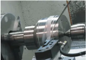
steel respectively as compared to the conventional Fig. 1(a): Machining with conventional coolant supply methods [4, 5].
The Ti-6Al-4V alloy is considered the most widely used titanium alloy in industry and accounted for about 60% of the total titanium production [6]. The alloy generally contains approximately 90% titanium, 6% aluminium, 4% vanadium and minor phases such as Iron, Carbon, Oxygen and Nitrogen [7]. This material generally has excellent mechanical properties, high corrosion resistance, high operating temperature and high
strength-to-weight ratio. The Ti-6Al-4V being used widely Fig. 1(b): High Pressure Waterjet Asissted Machining in aerospace and marine applications such as in rocket (HPWAM)
motor cases, blades, disks and turbines [8].
The Ti-6Al-4V alloy is also known to be among the difficult-to-cut materials due to its mechanical properties and poor thermal conductivity [8]. Machining Ti-6Al-4V alloy normally consumeds an excessive concentration of temperature at the cutting interfaces, which, under severe conditions, which will cause various types of thermal damage on the cutting tool and the machined component
[1-5]. Therefore, machining Ti-6Al-4V alloy is Fig. 2(a): Uncoated carbide inserts recommended to be undertaken under wet conditions to
reduce the excessive cutting temperature and eliminate the possibility of surface deterioration [1-5]. The use of HPWAM is one of the possible alternatives to machine Ti-6Al-4V effectively. The objective of this paper is to investigate the HPWAM performance when machining Ti-6Al-4V titanium alloy. The evaluations are based on the tool life, wear mechanisms, surface profile and chip
formations. The result of HPWAM is compared with the Fig. 2(b): The tool holder machining with conventional coolant to see the
advantage of this hybrid technique in improving The cutting speed, feed rate and depth of cut were kept productivity of machining Ti-6Al-4V alloy. constant at 110 m/min, 0.15 mm/rev and 0.5 mm MATERIALS AND METHODS a commercially available Ti-6Al-4V alloy. The tests were Machining tests were carried out on Colchester Fig. 2(a) with special tool holder designed for high MASTIFF CNC machine in two different coolant pressure application as shown in Figure 2 (b). The environments: conventional coolant supply as illustrated properties of coolant, workpiece material and cutting tool in Figure 1(a) and High Pressure Waterjet Assisted used in this study are illustrated in Tables 1, 2 and 3 Machining (HPWAM) as illustrated in Figure 1(b). respectively.
Table 1: Physical Properties of Ti-6Al-4V Alloy
0.2% Proof Elongation Density Melting Measured hardness Thermal conductivity
Tensile strength (MPa) stress (MPa) (%) (kg/m )3 point (°C) (CI - 99%)* HV at 20°C (W/m.°C)
100
900 to 1160 830 8 4430 1650 Min.= 297 Max. = 410 6.6
* CI: Confidence interval of 99 %, represented by the minimum (Min.) and maximum (Max.) values
Table 2: Properties of Uncoated Carbide 883 Grade Tool insert
Chemical Hardness Density Heat Thermal
ISO Designation Composition (wt %) (Knoop) GPa (kg/m )3 Capacity J/kg.°C conductivity W/m.°C Grain size (µm)
CNMG 120412 – M1 93.8 % WC, 6% Co, 0.2% (Ta, Nb)C 13 (1760 HV) 14950 241 11 1.0
Table 3: General Properties of Coolant
Viscosity of coolant Viscosity of coolant after
Major Compo-sition Concen-tration in oil phase (cSt) mixed with water (cSt) Average Surface Tension (mN/m) pH
Fatty acid 6% 65 1 41.51 9.35
The tool wear is measured during each machining test with tool life criterion in accordance with ISO 8688-2 (maximum flank wear, VBmax of 0.3 mm). The surface finish is measured with a stylus type instrument (Surtronic 10) and the chips were collected after each machining test. The Scanning Electron Microscope (SEM) was then used
in order to analyze the modes of tool wear, surface profile Fig. 3: Comparison of tool life recorded when machining and chip formation after machining. Ti-6Al-4V alloy with various cutting conditions
RESULTS AND DISCUSSION ineffective as cutting lubricants. On penetrating into the Tool Life: Figure 3 shows the comparison of tool molecular size can become lodged under the tight contact performance between machining with conventional and of the sliding boundary between tool-chip contact, which the HPWAM. The overall results from Figure 3 show that is a distance away from the tool edge [10].
machining Ti-6Al-4V alloy with HPWAM had a significant Additionally, the amount of coolant lodged will be effect on tool life. The improvements of up to 195% is wiped out by the moving chip, which creates further recorded when the coolant pressure is increased to 20.3 difficulties for the diffusion of the coolant into the cutting MPa when compared to machining with conventional region [11]. These difficulties combine with the high coolant supply. At the conventional coolant supply, the surface tension of coolant, i.e. 41.51 mN/m, promotes coolant may have failed to effectively penetrate the lower wettability properties due to the high attractive cutting zone, resulting in a lower tool life. This is a general forces between the coolant molecules [12]. These observation as shown in Figure 3 where the best recorded phenomena render this coolant inefficient to provide tool life when machining with conventional coolant adequate cooling and lubrication, resulting in lower tool just reaches 18 min, 63% lower than for HPWAM under performance at a conventional coolant supply.
110 m/min cutting speed. The tool life is increased to 29.7 min as the machining The inability of this coolant to perform at the with high pressure coolant is applied with 11 MPa. conventional coolant supply is reflected in its low This accounts for about 63% improvement relative to pressure as well as its properties, as shown in Table 3. machining with the conventional coolant supply. The tool The oil phase of this coolant has a very high viscosity of life performance is further increased to 54 min when the 65 cSt, as compared to water (1 cSt). The high viscosity of coolant pressure is increased to 20.3 MPa. This result the oil phase of this coolant may imply the presence of shows that high velocity flow of coolant at a high large structural components inside the coolant's molecular pressure has a significant effect in providing the adequate structure [9]. Coolants with a large molecular size normally cooling and lubrication at the tool-chip interface, this have poor interfacial penetration and are relatively leading to a better machining performance.
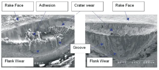
Fig. 4(a): Worn cutting tool after machining Fig. 4(b): HPWAJ under a pressure of 11MPa
It is proven that there is a high resistance to flow sliding action became more pronounced resulting to the without the coolant disintegration, if the coolant used has wider development of flank wear until it is displaced a high viscosity [13]. At the higher pressure of 11 MPa, towards the nose region. During this stage, higher the flow of coolant manages to give impact with sufficient temperature and friction developed in a small area momentum to create a larger gap with spaces for the resulting in more abrasion occurring in a concentrated coolant to penetrate further into the tool-chip and region. This resulted in tremendous wear at the nose tool-workpiece interfaces. This enables closer contact of region, accelerating beyond the 0.3mm rejection criterion the coolant with the tool tip, which exposes the coolant to within a short time [15].
the higher cutting temperature. During penetration of the The crater wear appears on the rake face of the tool coolant into the tool-chip interface, the amount of fatty as shown in Figure 4(a) and Figure 4(b). Crater wear is acid inside the coolant can be physically absorbed into characterized by a wide crater formation at the rake face of the contact interface to form a relatively lower shear a carbide tool where contact with the tool-chip interface strength film [14]. This film, although extremely thin, is takes place. An observation of these crater areas shows capable of reducing friction at the tool chip interface and a thin layer of molten metal attached to the crater face of preventing the re-welding of asperities on the back the cutting tool. The formation of this thin layer is surface of the chip, thus reducing the wear rate of the attributed to the molten film of Ti-6Al-4V alloy that cutting tool. This prevents friction in the areas affected by adherences to the rake face of the cutting tool results in the lubricant film and minimises heat transfer to the adhesive wear occurring in some locations. Adhesion cutting tool, thus prolonging tool life. wear is attributed to the detachment of particles from the Wear Mechanism: Some samples of the tool wear when sliding chip. During machining, individual grains of machining with conventional and HPWAM are shown in carbide structure are detached from the tool surfaces and Figure 4. Almost all the worn surfaces showed similar carried away from the tool-chip interface by the sliding characteristics with the failure modes being dominated by chip. As the machining continues, the high temperatures flank and crater wear. Flank wear occurs when the flank generated provide more substitutional grain detachment face of the cutting tool abrades against the workpiece between at the tool-chip interface, which further weaken material. Inside the flank wear region, an enlarged view of the areas of the cutting tool exposed to the high the flank face for the inserts shows that scratches, temperatures. With tribological sliding between the grooves and ridges appear across most of the observed cutting tool and the chip, severe seizure takes place area Figure 4(a). This suggests that abrasion by carbide causing loss of the material at the tool’s rake face and grains was the dominant wear mechanism During increase in the depth of the crater wear [15].
machining, the greater cutting temperatures and stresses
Material Side Flow
Fig. 5: Surface roughness variation recorded when conventional coolant supply machining Ti-6Al-4V alloy with all cutting
conditions
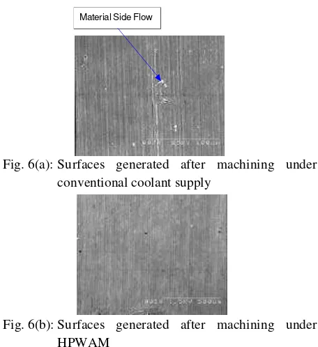
Results from Figure 5 also indicate that machining with all cutting conditions considered had a negligible difference on the surface finish generated. Therefore, it can be established that the surface finish generated with both
machining with conventional and HPWAM is not Fig. 6(b): Surfaces generated after machining under adversely affected by the cutting conditions investigated. HPWAM
The relatively low surface roughness can be
attributed to the fact that the introduction of coolant may ductility of the machined surface. When the cutting tool cool the tool surfaces to prevent or reduce adhesion wear shears the metal, the relative motion between the tool and therefore maintaining the nose radius of the cutting tool workpiece generates surface tearing leaving displaced for a longer period. The sharp edges of the cutting tool marks in the direction opposite of the feed mark trails [17]. will act as the stress concentrators that enables the This severe surface damage would change the surface surface to be machined cleanly, thus resulting in the lower profile and average surface roughness values leading to surface roughness values and better surface finish [16]. the deterioration of the machined surface quality. This Such a low surface roughness reflects the ability of process is also reported to be accelerated by the HPWAM to secure better dimensional accuracy whilst development of nose wear in the tool edge [17].
improving the fatigue strength of the machined
component. Chip Formations: During machining with both
The surfaces generated after machining under conventional and high pressure coolant supply, two conventional coolant supply are shown illustrated in different forms of chip were produced: a long, tubular, Figure 6. It shows that the surfaces generated under all chip-shape when machining under conventional coolant the investigated conditions were not adversely affected flow as shown in Figure 7(a) and a small, segmented, and were free from damage such as cracking, tearing and C-shaped chip when machining with 11 MPa and 20.3 rupture. There is also no evidence of serious surface MPa coolant pressures as illustrated in Figure 7(b) and smears and chatter marks after machining the Ti-6A-4V Figure 7(c). The formation of continuous chips is alloy with various coolant grades. This evidence is attributed to the inability of the applied coolant to reflected from the results for the surface roughness where effectively break the chips [3]. Continuous and snarled low surface roughness is recorded for most of the cutting chips are undesirable because they usually wrap
conditions. themselves around the workpiece or get tangled around
Fig. 7 (a): Chips generated under conventional coolant
supply ACKNOWLEDGEMENTS
Fig. 7(b): Chips generated under HPWAM at 11 Mpa Technology in Finishing Turning of Ti-6Al-4V Alloy
Fig. 7(c): Chips generated under HPWAM at 20.3 MPa 3. Machado, A.R., J. Wallbank, I.R. Pashby and high-momentum jet of pressurised coolant exerts on the Control when Machining Ti-6Al-4V and Inconel 901 deformed chip [3]. In HPWAM, the stable flow of coolant using High Pressure Coolant Supply, Machining tends to lift the chip up after passing through the Science and Technology, 2(1): 1-12.
deformation zone. Coolant volume fills the gap between 4. Ezugwu, E.O. and J. Bonney, 2004. Effect of the chip and the tool rake face, allowing the coolant to High-pressure Coolant Supply when Machining penetrate a smaller area of the chip. At a given supply Nickel-base, Inconel 718, Alloy with Coated Carbide power, a high-pressure coolant stream bends the chips Tools, Journal of Materials Processing Technology, upwards causing the breakage of the chips into smaller pp: 153-154: 1045-1050.
segments. 5. Kramar, D., P. Krajnik and J. Kopac, 2010. Capability
CONCLUSION Hardened Piston Rods. Journal of Materials
This study concludes that machining Ti-6Al-4V 6. Beal, J.D., R. Boyer and D. Sanders, 2006. Forming of Titanium alloy under HPWAM gave better cutting Titanium and Titanium Alloys. (Volume 14B). The performance of up to 195% improvement over machining Boeing Company ASM Handbook.
with conventional coolant supply. The predominant wear 7. Matthew, J.D., 2000. Titanium: A Technical Guide, mechanisms when machining under the cutting conditions (2 ed.). Materials Park, Ohio: ASM International. are abrasive and adhesive wear. Surface roughness values 8. Ezugwu, E.O. and Z.M. Wang, 1997. Titanium recorded when machining Ti-6Al-4V alloy under the Alloys and Their Machinability - A Review, cutting conditions are generally below the 1.6 ìm rejection Journal of Materials Processing Technology, criterion. The HPWAM significantly reduces the chip 68(3): 262-274.
size, resulting in a reduction in the tool-chip contact and improvement in lubrication at the contact interfaces. This paper provides the understanding and correct use of HPWAM especially when machining Ti-6Al-4V alloy. It can be suggested that the future work for this study should be focused more into the machining trials of HPWAM using different types of coolants.
The authors would like to thank Ministry of Higher Education (MOHE), Malaysia and Faculty of Manufacturing Engineering, Universiti Teknikal Malaysia Melaka (UTeM) for their support.
REFERENCES
1. Da, Silva R.B., 2007. High Pressure Cooling with Various Cutting Tools, PhD Thesis, London South Bank University, pp: 299.
2. Mohd Hadzley, A.B., R. Izamshah, A. Siti Sarah and M. Nurul Fatin, 2012. Finite Element Model of Machining with High Pressure Coolant for Ti-6Al-4V alloy, Malaysian University Conference on Engineering and Technology, Perlis, Malaysia, pp: 19-21.
E.O. Ezugwu, 1998. Tool Performance and Chip
of High Pressure Cooling in the Turning of Surface Processing Technology, 210(2): 212-218.
9. Fox, N.J. and G.W. Stachowiak, 2007. Vegetable 14. Shashidhara, Y.M. and S.R. Jayaram, 2010. Vegetable oil-based lubricants- A review of oxidation, Tribology Oils as a Potential Cutting Fluid-An Evolution, International, 40(7): 1035-1046. Tribology International, 43(5-6): 1073-1081. 10. Postkinov, S.N., 1967. Penetrating Ability of Cutting 15. Jawaid, A., C.H. Che-Haron and A. Abdullah, 1999.
of Cutting Fluids, Wear, 10(2): 142-150. Tool Wear Characteristics in Turning of Titanium 11. Williams, J.A. and D. Tabor, 1977. The Role of Alloy Ti-6246, Journal of Materials Processing
Lubricants in Machining, Wear, 43(3): 275-292. Technology, 92(93): 329-334.
12. Kumar, G. and N.K. Prabhu, 2007. Review of 16. Astakhov, V.P., S.V. Shvets and M.O.M. Osma, 1997. Non-reactive and Reactive Wetting of Liquids on Chip Structure Classification Based on Mechanics of Surfaces, Advances in Colloid and Interface Science, its Formation, Journal of Materials Processing
133(2): 61-89. Technology, 71(2): 247-257.
13. Cheng, Y.F., W.S. Sheau and Y.H. Tzeng, 2009. 17. Kishawy, H.A. and M.A. Elbestawi, 1999. Effects of The Effect of Orifice Lead Cutting Edge Distance and Process Parameters on Material Side Flow during Fluid Viscosity on Jet Performance in High-velocity Hard Turning, International Journal of Machine Waterjet Cutting Systems, The International Tools and Manufacture, 39(7): 1017-1030.