IOSR Journal of Mechanical and Civil Engineering (IOSR-JMCE) ISSN: 2278-1684 Volume 3, Issue 2 (Sep-Oct. 2012), PP 20-23 www.iosrjournals.org
www.iosrjournals.org 20 | Page
Modeling of a Jig Sampling and its Application in Disc Cutter
Tools
S. H. Yahaya
1, Haeryip Sihombing
2, M. Y. Yuhazri
3and H. Hasib
41, 2, 3, 4
Faculty of Manufacturing Engineering, University of Technical Malaysia Melaka, 76100 Melaka, Malaysia
Abstract: The operations of preparing the deform sample and round bar mainly consist of the calculation of the bar’s unit weight. The Sampling process is conducted through the two cutting flows such as in line production and disc. The problems are then occurred in the second flow (in disc) in performing the cutting process on a certain length. Modeling of the jig sampling is used to solve this problem and also fully discussed throughout this paper.
Keywords- Bar, Jig Sampling, Mass Interval, Unit Weight
I. INTRODUCTION
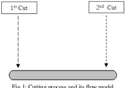
The operations of preparing the deform sample and round bar mainly contain of the calculation of unit weight in the bar. Sampling process has two flows, which are gas cutting in line production and disc cutting. The problem occurred in the second flow where in this flow, the operator needs to cut deform or round bar in certain length [1]. The operators will cut the both sides of bar, and these processes can prevent the wasted time producing, human errors and expenses [2]. This problem can be solved by introducing the sampling of a jig. In addition, the process of sampling is employed in disc cutter table to assist the workers work efficiently. The flow model is shown in Fig. 1.
The procedures are to be taken to gauge the unit weight such as to obtain the sample (bar) from cooling bed, crop both end, weight samples, measure length and calculate the unit weight. Unit weight can be calculated [3] as in (1).
Modeling of a jig sampling and its application in disc cutter tools
www.iosrjournals.org 21 | Page Fig. 2: Technical model applied in disc cutter table
2.2 Function and Assembly Descriptions
The jig is designed to control the dimension of the sample bar in accordance to -x axis [4]. With reference to the instruction booklets, bar’s length should be in 600 mm to ensure that every facet of the sample can be cut to this size, accurately. Moreover, -x axis is used as a marker to the parameters such as position and dimension. The marker is performed by the counter weight and its location at the end of the vise table in automated position (Fig. 3).
Fig. 3: Assembly model during the cutting process
III. METHODOLOGY
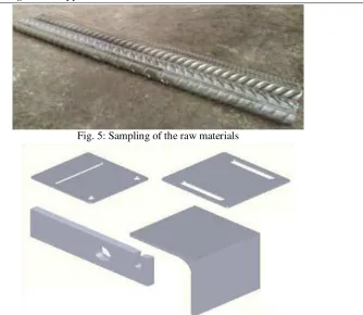
The following process flow diagram will be applied in jig sampling. The detailed process is explored in Fig. 4. In addition, the supporting equipments have been employed to accomplish this sampling such as the welding set, vise, oxy-cutting, disc cutter with drilling and milling machines. The sampling of raw materials is demonstrated in Fig. 5 while the applied designs that are used in this sampling are shown in Fig. 6.
Modeling of a jig sampling and its application in disc cutter tools
www.iosrjournals.org 22 | Page Fig. 5: Sampling of the raw materials
Fig. 6: The supporting designs of the sampling process are completely designed by Solidworks
IV. RESULT AND DISCUSSIONS
The sampling began by calculating unit weight as in (1) if the parameters such as bars' length and weight are known. For example, if bar size equivalents to 20 mm, therefore, the true value of unit weight, S is equal to 0.25 Kgm-1 in the reference to the existing method (normal implementation). For this case, the bars' length and weight of this size are calculated to be 0.6 m and 0.15 Kg.
As a result, the unit weight is 0.25 Kgm-1 using (1) and the above inputs. Notice that, the calculated and true values have the same value. Then, tolerance, ζ is equal to zero. We extend this calculation to create the mass interval, λ of unit weight to find out either the calculated unit weight is accepted (along the interval) or vice verse. This concept is continued by fitting the error to be as ±0.05. The λ is formulated as in (2). Various computations of the unit weights in accordance to the bar size using (1) and (2) are also shown in Table 1. We can see clearly that the calculated values (in fourth column) are in the range of λ (Table 1). The ζ have the small values after comparing with S. Therefore, we can conclude that the calculated values (in fourth column) are the acceptable values. Table 1: Unit weight’s computations in the modeling of a jig sampling
Modeling of a jig sampling and its application in disc cutter tools
www.iosrjournals.org 23 | Page suggest the integrations between sampling and modeling techniques to be applied in engineering fields in order to help and solve the related problems. These techniques are simple and easy to use and handle.
Acknowledgements
This research was supported by Universiti Teknikal Malaysia Melaka. The authors gratefully acknowledge to everybody for their helpful comments.
REFERENCES
[1] S. Kaldor, A. M. Rafael, and D. Messinger, On the CAD of Profiles for Cutters and Helical Flutes - Geometrical Aspects, CIRP Annals - Manufacturing Technology, 37(1), 1988, 53-56.
[2] R. Iankov, Finite element simulation of profile rolling of wire, Journal of Materials Processing Technology, 142(2), 2003, 355-361. [3] T. El Maaddawy, and K. Soudki, A model for prediction of time from corrosion initiation to corrosion cracking, Cement and
Concrete Composites, 29(3), 2007, 168-175.