Melaka, Malaysia [email protected]
Sydney, Australia [email protected]
Abstract—The quasi-Z-source inverter (qZSI) which originated from the Z-source inverter (ZSI) topology provides an alternative for the conventional two stages DC-DC/DC-AC PV based inverter system with less component number, simpler topology and overcomes some of the limitations and problem associated with the conventional inverter topology. In the application of grid-connected PV inverter system, power storage becomes a critical requirement as a backup to fulfill the power demand. In this context, the qZSI topology has the advantage of easy connection with the storage element with a very minimal modification. This paper presents the grid-connected PV inverter system based on the qZSI topology with a storage capability. The main elements required for the system; the MPPT, dc-link and current control, and the energy storage are detailed plus the analysis of the circuit operation. The simulation results demonstrate the system able to work accordingly.
Keywords- quasi-Z source; grid-connected; PV inverter; battery storage
I. INTRODUCTION
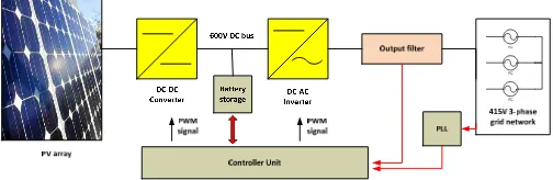
The use of photovoltaic (PV) energy as an alternative to generate electricity has becomes significant in the recent years. A PV inverter is widely used to convert the photovoltaic energy into usable electrical energy as most of the demands are in the AC voltage, either for local loads or supplied into the grid. This in general requires an application of two stages conversion as shown in Fig.1; the DC-DC conversion stage to regulate the output voltage from the PV array to certain required level, and the DC-AC conversion stage to produce the usable sinusoidal AC voltage.
The mentioned conventional PV inverter topology however has several drawbacks such as the two conversion stages which lead to more losses, noise and distortion; complexity in control and additional components that cause the cost to increase. The Z-source inverter (ZSI), as originally proposed by Feng [1] as
Figure 1. PV based grid-connected inverter system
in Fig.2(a) offers a simpler single stage inverter topology with several advantages; far instances a more boosting capability for higher voltage regulation, eliminate the shoot through problem in the overlapped switches and less components that lead to lower cost.
Then several more improvement was made to the topology such as in [2], [3], and [4]. Among them, the quasi-Z source inverter (qZSI) as shown in the above Fig. 2 (b) has an advantage of a lower voltage rating component compared to the original ZSI. In the context of application for the PV inverter, ability to have energy storage is important as a backup for the system in situation where the energy harvested from the PV array cannot fulfill the required demand. Considering the unique topology it has, the qZSI is able to have the storage element connected with a very minimal modification, for example as shown in the following Fig. 2(b).
Several works already studied the about the qZSI topology with battery storage such as in [5] – [7]. The works discuss mainly on how the storage battery is connected and the power flow management at different modes of operation, i.e, when the battery is charged, discharged or disconnected from the system. All the works also proposed the battery to be connected in parallel with the second capacitor on top of the topology as in Fig.2 (b) with additional switch to control the current flow to the battery. The proposed connection is simple without much modification.
The provided circuit analysis to be detailed in the next section shows that voltage across both the capacitors is inter-related to each other and connecting a battery which has its own potential voltage across the terminal in real situation causing a difficulty in controlling the other capacitor which is used to control the dc-link voltage and to achieve the MPPT operation such as in [5] and [6].
(b)
Figure 2. (a) Z-source inverter (b) quasi Z-source inverter topology
In this paper a different storage connection method is proposed which lessen the effect of battery terminal voltage to the control and operation of the MPPT and the dc-link voltage. The analysis of the circuit operation, the MPPT and the current control are also highlighted. Based on the simulation result, it is shown that the grid-connected qZSI able to work accordingly to the requirement. Overall, this paper contributes to another variation in the connection method of battery storage based on the qZSI topology applied in the grid-connected PV inverter system.
II. ANALYSIS OF CIRCUIT OPERATION
There are two states of operation in the conventional voltage source inverter (VSI); the active states when a non-zero voltage exists across the bridges and the non-zero states when either all upper and lower transistors are in ON or OFF condition (Q1Q3Q5/Q4Q6Q2 = 000 or 111) to produce a zero
voltage condition across the bridges. In the qZSI, a shoot through condition (short circuit) is purposely introduced during the zero states. The following Fig. 3 shows the equivalent circuit of the qZSI during the shoot-through and the non-shoot-through states.
When the qZSI is in a shoot through condition for a duration of T0 from switching cycle of T, based on the circuit
diagram of Fig. 3(a), the following equations can be defined.
V
in+
V
c2=
v
L1V
c1=
v
L2v
out=
0
(1) Then when the qZSI is in an active states condition for duration of T1 from switching cycle of T, the followingequations (2) and (3) can be defined.
(a)
(b)
Figure 3. qZSI circuit during (a) shoot-trough state (b) non-shoot-through state
v
L1=
V
in−
V
c1=
V
in−
v
out+
V
c2 ∧(2)
v
L2=
V
c1−
v
out=
−
V
c2∧
(3) From the above (1), (2) and (3), for the whole one switching period of T, assuming the average voltage across the inductor L2, VL2 is zero in steady state, the following
equations can be defined.
(
)
0
1 1 1 0 2 1 1 0
2 =
− ⋅ + ⋅ = − ⋅ + ⋅ =
∧
T v V T V T
T V T V T V
out c c
c c
L (4)
T
0⋅
V
c1=
T
1⋅
V
c2 cv
outT
T
V
∧
⋅
=
11 (5)
Based on equations in (3), (4) and (5), next the following is defined.
out
c
v
T
T
V
∧
⋅
=
02
v
out=
V
c1+
V
c2∧
(6) Same for the average voltage across the L1, VL1 over one
switching period can be defined as follow.
(
)
(
)
(
)
0
2 ^ 1
2 0
1 1
2 0 1
= + − ⋅ + + ⋅ =
− ⋅ + + ⋅ =
T
V v V T V V T
T
V V T V V T V
c out in in
c
c in in
c L
(7)
Based on equations (5), (6) and (7), next the following is defined.
out
V
inT
T
T
v
⋅
−
=
∧
0 1
V
in=
V
c1−
V
c2 (8)T, the following is obtained.
out c
V
inD
D
V
V
⋅
−
−
=
=
2
1
1
1 (11) It can be shown that by varying the shoot through time over one switching cycle, the input voltage can be boosted accordingly. As for the case the input voltage comes from the output of PV arrays (Vin = Vpv), from equation (11), if the
capacitor voltage Vc1 can be controlled to be constant, the
input voltage Vpv increases when the shoot-through time is
decreased, and decreases when the shoot-through time is increased as in equation (12).
1
1
2
1
c
pv
V
D
D
V
⋅
−
−
=
(12)Considering this fact for the case of MPPT implementation, the maximum power point voltage (Vmpp = Vpv) can be tracked
by adjusting the shoot-through duty ratio D. III. SYSTEM DESIGN
In the PV based grid connected inverter system, the multi-point power tracking (MPPT), DC link voltage and current control and the battery storage connection are the main component to be designed and configured. The following sub-sections detail each of the components involved.
A. System Specification
Table I shows the specification used in the design of PV based qZSI system and Fig. 4 shows the overall PV inverter system. The source of the system is the PV array with the maximum power of 5 kW. The voltage of the PV array terminal is boosted by the impedance network of L1, L2, C1
and C2 to produce average 800V across the inverter input. The
inverter then produces the sinusoidal current to be supplied to the grid and the synchronization is made through the phase locked-loop (PLL) block.
B. MPPT
The MPPT method to be used is based on the modified perturbed and observed (P&O) method considering its simple algorithm which is widely used. Based on the equation (12), it is known that while regulating the capacitor voltage Vc1
constantly, the optimal voltage for the PV array Vpv = Vmpp
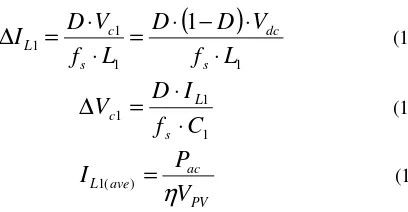
voltage and current ripple. The following equations (13) to (15) are used to determine the appropriate values [8].
(
)
1 1
1 1
1
L
f
V
D
D
L
f
V
D
I
s
dc
s c L
⋅
⋅
−
⋅
=
⋅
⋅
=
∆
(13)
1 1 1
C
f
I
D
V
s L c
⋅
⋅
=
∆
(14)
PV ac ave
L
V
P
I
η
=
) (
1 (15)
where D : shoot-through duty ratio, fs : switching frequency,
Vdc : dc link voltage across the bridges, Pac : AC power to the
grid, : power efficiency, Vpv : output voltage of PV array.
D. Voltage and Current control
The purpose of the voltage control is to have the value across the capacitor and average dc-link voltage across the bridges constant at the required value. The required value of voltage across the bridge Vdc which is equal to Vout in equation
(9) can be defined as follow.
m
max⋅
V
dc≥
2
V
ac(max) (16)where mmax : maximum modulation index; Vac(max) is the
maximum rms voltage of the grid.
TABLE I. PARAMETERS OF DESIGN SPECIFICATION
Parameters Values
1. Maximum power of PV
array 5 kW
2. PV array voltage &
current at Pmax 235.9 V, 21.36 A
3. DC bus voltage 800 V
4. Grid connection 3-phase secondary network 415 Vrms (240 Vrms per phase)
5. Maximum power to grid 5 kVA 6. Switching frequency 10 kHz
7. Standard / reference 1. AS4447 Grid Connection of Energy Systems via Inverters 2. IEEE 1547 Standard for
Figure 4. Block diagram of the overall PV inverter system
Figure 5. Flowchart of modified P&O method for MPPT
As for the current control strategy, a synchronous PI current control in two-phase rotating (d-q) frame is applied [9]. The advantage of this control strategy is the three phase symmetric grid voltage and current that can be transformed into a dc variables and by adopting a PI controller, it is possible to realize a no steady state error adjustment. As shown in Fig. 6, Id and Iq are the d and q component of
dq-transformation of the 3-phase output current to the grid. Considering a unity power factor, the reactive power is assumed to be zero. The Id is compared with the reference
signal Iref from the outer voltage PI controller signal based on
the difference between the actual voltage and the desired voltage of Vc1 which represent the average dc link voltage
across the inverter. The objective of the inner current controller is to create a PWM reference signal which will control the current flow thus regulating the dc link voltage at almost constant value.
Figure 6. A synchronous PI current control
E. Battery storage connection
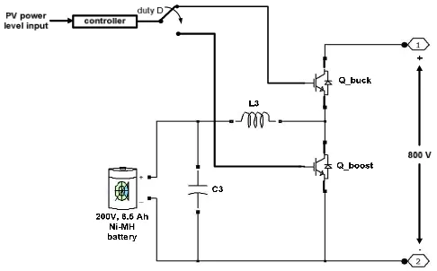
In this work, the battery storage unit is consist of one rechargable Ni-MH battery with nominal voltage of 200V and fully charged voltage of 235V with capacity of 6.5 Ah. As shown in Fig.7 (a) the battery storage unit is connected in parallel to the capacitor controlled at 800V. From Fig.8 a bidirectional dc-dc converter is used for the recharge and discharge of the battery. During the recharge mode 2, the dc-dc converter functions as a buck converter, converting the capacitor voltage of 800V to 200V across the battery. Then during the discharge mode 4, the dc-dc converter functions as a boost converter, converting the battery voltage of 200V to 800V across the capacitor. In both buck and boost operation the switch gate is controlled to regulate the amount of current flowing into and out of the battery. In order to realize a condition of mode 5, a circuit breaker and additional switch is added as shown in Fig. 7 for the circuit to operate as conventional VSI.
The modes of operation of the grid connected PV inverter system with battery storage can be different depends on the requirement during the system installation. In this work the following 4 modes of operation are considered.
just enough to feed the grid (5% to < 75% of maximum power). All the power obtained from the PV array is directly delivered to the grid.
• Mode 4 : power obtained from the PV array is less than 5% of the maximum power. Additional power is discharged from the battery to support feeding the grid.
• Mode 5 : no power is obtained from the PV array due to zero insolation (eg. at night). PV array has to be disconnected and the circuit operates as a conventional voltage source inverter (VSI).
IV. SIMULATION RESULT
The simulation with MATLAB SIMULINK is carried out to evaluate the PV inverter system behaviour based on the mode of operation detailed previously. Table II shows the value of some of the important components based on Fig. 4. Due to limitation of memory, the simulation is conducted for a short period of 4 seconds just enough to show the operability of the designed system.
Fig. 9 shows the power obtained from the PV array based on the preset values of insolation level and temperature of 25°C. It is shown that the MPPT is able to track the maximum power level accordingly at different insolation. The maximum power of 5 kW is obtained during the period of maximum insolation of 1 kW/m2.
(a)
Figure7. Battery storage unit connection across the C1 capacitor with
additional circuit breaker and switch
Figure 8. Battery connection inside the storage unit with bidirectional dc-dc converter
TABLE II. VALUE OF COMPONENTS
Parameters Values
1. L1, L2 33 mH
2. C1, C2 330 uF
3. Cin 1000 uF
4. Lf 10 mH
5. Grid inductance,
resistance 0.2 , 0.1 mH
6. Initial battery charge
capacity 75%
Fig. 10 shows the voltage across capacitor C1 regulated at
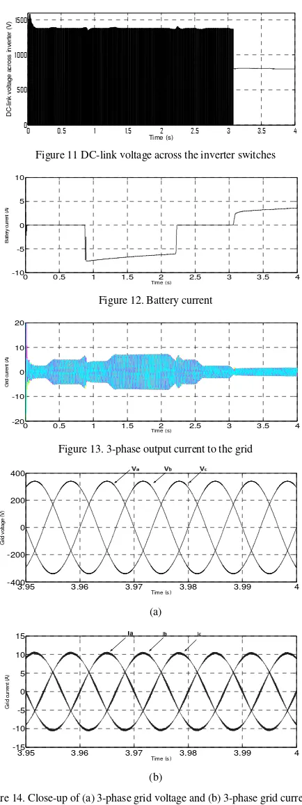
800 V, which confirms the effectiveness of the voltage and current control method used. Fig. 11 shows a dc-link voltage across the inverter switches where it is shown that the circuit change its operation to conventional VSI when the received insolation is zero. In Fig. 12 approximately 5A of current flows to the battery to recharge it during mode 2 operation and 5A of current discharges from the battery when the circuit enters mode 4 & 5. As can be seen in Fig. 13, during zero insolation, the battery discharges supplying current to the grid.
Time (s)
P
o
w
e
r
o
b
ta
in
e
d
f
ro
m
P
V
a
rr
a
y
(
W
)
Figure 9. Power obtained from the PV array
Time (s)
V
o
lt
a
g
e
a
c
ro
s
s
C
1
(
V
)
Fig. 14 (a) & (b) shows the close-up of the grid voltage and current where both are in-phase to achieve good power factor. This is supported by the total active power received at the grid shown in Fig. 15.
Time (s) D C -l in k v o lt a g e a c ro s s i n v e rt e r (V )
Figure 11 DC-link voltage across the inverter switches
0 0.5 1 1.5 2 2.5 3 3.5 4
-10 -5 0 5 10 Time (s) B a tt e ry c u rr e n t (A )
Figure 12. Battery current
0 0.5 1 1.5 2 2.5 3 3.5 4
-20 -10 0 10 20 Time (s) G ri d c u rr e n t (A )
Figure 13. 3-phase output current to the grid
3.95 3.96 3.97 3.98 3.99 4
-400 -200 0 200 400 Time (s) G ri d v o lt a g e ( V ) (a)
3.95 3.96 3.97 3.98 3.99 4
-15 -10 -5 0 5 10 15 Time (s) G ri d c u rr e n t (A ) (b)
Figure 14. Close-up of (a) 3-phase grid voltage and (b) 3-phase grid current
0 0.5 1 1.5 2 2.5 3 3.5 4
0 1000 2000 3000 4000 5000 6000 Time (s) A c ti v e p o w e r re c e iv e d a t g ri d ( W )
Figure 15. Total active power at the grid
V. SUMMARY
The paper presents the design and simulation of the grid- connected PV inverter system based on the qZSI topology with storage capability. Based on the circuit analysis, it is shown that the qZSI can be implemented together with the system to achieve the MPPT, as well as voltage and current control for injecting current to the grid with good power factor, grid synchronization and battery storage. A new method of battery storage connection has been proposed and the simulation results show that the PV inverter system with storage works satisfactorily. Hardware implementation and critical power quality at the grid-connection point will be carried out in future works.
ACKNOWLEDGMENT
The author would like to thank the Universiti Teknikal Malaysia Melaka (UTeM) and Ministry of Higher Education Malaysia for the sponsorship given in conducting this work.
REFERENCES
[1] Peng, F.Z. 2002, "Z-source inverter", Conference Record - IAS Annual Meeting (IEEE Industry Applications Society), pp. 775.
[2] Anderson, J. & Peng, F.Z. 2008, "Four quasi-Z-Source inverters", PESC Record - IEEE Annual Power Electronics Specialists Conference, pp. 2743.
[3] Gajanayake, C.J., Lin, L.F., Beng, G.H., Lam, S.P. & Kian, S.L. 2009, "Extended boost Z-source inverters", 2009 IEEE Energy Conversion Congress and Exposition, ECCE 2009, pp. 3845.
[4] Strzelecki, R., Adamowicz, M., Strzelecka, N. & Bury, W. 2009, "New type T-source inverter", CPE 2009 - 6th International Conference-Workshop - Compatability and Power Electronics, pp. 191.
[5] Cintron-Rivera, J.G., Li, Y., Jiang, S. & Peng, F.Z. 2011, "Quasi-Z-Source inverter with energy storage for Photovoltaic power generation systems", Conference Proceedings - IEEE Applied Power Electronics Conference and Exposition - APEC, pp. 401.
[6] Li, F. et al. 2011, "Quasi-Z source inverter with battery based PV power generation system", 2011 International Conference on Electrical Machines and Systems, ICEMS 2011.
[7] Sun, D., Ge, B. et al. 2011, "Power flow control for quasi-Z source inverter with battery based PV power generation system", IEEE Energy Conversion Congress and Exposition: Energy Conversion Innovation for a Clean Energy Future, ECCE 2011, Proceedings, pp. 1051.
[8] Farhangi, B. & Farhangi, S. 2006, "Comparison of z-source and boost-buck inverter topologies as a single phase transformer-less photovoltaic grid-connected power conditioner", PESC Record - IEEE Annual Power Electronics Specialists Conference.