CUTTER PATH STRATEGY FOR MACHINING
CRANIOFACIAL MEDICAL IMPLANT PEEK COMPOSITE
MOHAMAD RIDWAN BIN RAMLI
B050910096
UNIVERSITI TEKNIKAL MALAYSIA MELAKA
CUTTER PATH STRATEGY FOR MACHINING CRANIOFACIAL
MEDICAL IMPLANT PEEK COMPOSITE
This report submitted in accordance with the requirement of the UniversitiTeknikal Malaysia Melaka (UTeM) for the Bachelor Degree of Manufacturing Engineering
(Manufacturing Process) (Hons.)
by
MOHAMAD RIDWAN BIN RAMLI
B050910096
861020-29-5569
UNIVERSITI TEKNIKAL MALAYSIA MELAKA
BORANG PENGESAHAN STATUS LAPORAN PROJEK SARJANA MUDA
TAJUK: Cutter Path Startegiy For Machining Craniofacial Medical Implant PEEK Composite
SESI PENGAJIAN: 2012/13 Semester 2
Saya MOHAMAD RIDWAN BIN RAMLI
mengakumembenarkanLaporan PSM inidisimpan di PerpustakaanUniversitiTeknikal Malaysia Melaka (UTeM) dengansyarat-syaratkegunaansepertiberikut:
1. Laporan PSM adalah hak milik Universiti Teknikal Malaysia Melaka dan penulis. 2. Perpustakaan Universiti Teknikal Malaysia Melaka dibenarkan membuat salinan
untuk tujuan pengajian sahaja dengan izin penulis.
3. Perpustakaan dibenarkan membuat salinan laporan PSM ini sebagai bahan pertukaran antara institusi pengajian tinggi.
4. **Silatandakan (√)
SULIT
TERHAD
TIDAK TERHAD
(Mengandungi maklumat yang berdarjah keselamatan atau kepentingan Malaysiasebagaimana yang termaktub dalam AKTA RAHSIA RASMI 1972)
(Mengandungi maklumat TERHAD yang telah ditentukan oleh organisasi/badan di mana penyelidikan dijalankan)
AlamatTetap:
B1-06 Jalan SS6/3 Perumahan
Kastam Wilayah Persekutuan Kuala
Lumpur, 47310 Petaling Jaya
Tarikh: _________________________
Disahkan oleh:
Cop Rasmi:
DECLARATION
I hereby, declared this report entitled “Cutter Path Startegiy For Machining Craniofacial Medical Implant PEEK Composite” is the results of my own research
except as cited in the references.
Signature : ...
Author's Name : MOHAMAD RIDWAN BIN RAMLI
APPROVAL
This report is submitted to the Faculty of Manufacturing Engineering of UTeM as a partial fulfillment of the requirements for the degree of Bachelor of Manufacturing Engineering (Manufacturing Process) (Hons.). The member of the supervisory is as follows:
...
i
ABSTRACT
ii
ABSTRAK
iii
DEDICATION
iv
ACKNOWLEDGEMENT
Alhamdulillah, Thanks to the entire Almighty from Allah for giving me all the strength
and good health to complete this report without problems and barriers. This report is
finally completed with much assistance of many people.
I would like to express the deepest appreciation to Universiti Teknikal Melaysia Melaka
for providing such a brilliant facility such as equipment and machine for me to fulfil PSM requirement that’s need to use while the project is carry on .
Besides that, I am heartily thankful to my supervisor, Dr. Raja Izamshah Bin Raja
Abdullah, whose encouragement, guidance and support from the initial to the final level
enabled me to develop an understanding of the research. I am truly grateful for his the
time spent proofreading and correcting my many mistakes, his tolerance of my mistakes,
and his commitment to my future career.
In addition, I would like to thank all manufacturing engineering department lab staff for
giving me an opportunity to work in a good and productive environment. Their
continuous support and guidance whenever problems occurred while I was performing
new task is really an encouragement in making me to perform at my very best. This has partly contributed to the success of my research and the completion of this „Projek Sarjana Muda’.
Last but not least I would like to thank my friends especially those who help to
contribute the idea and solution while the research is carry on. Thank you.
v
2.2 Orthopedic Machining 6
2.2.1 Work Holding 8
2.2.2 Tooling 9
2.2.3 Material and Machining 9
2.2.4 Traceability 10
2.2.5 Fine Selection 10
2.3 Cutter Path In Milling Machining 11
2.4 Strategy for Surface Milling 13
2.4.1 Direction parallel 13
2.4.2 Contour Parallel 14
2.4.2 ZigZag 15
2.5 Machining performance 16
2.5.1 Surface Roughness 16
vi
2.5.3 Machining Time 17
2.6 Consideration in Milling Machining for PEEK Composite 18
2.6.1 Achievable Surface Finish 18
2.6.2 Tolerance 18
2.6.3 Cutting Temperature 19
2.6.4 Material Properties 19
CHAPTER 3: METHODOLOGY 13
3.1 Process Planning (Flow Chart) 13
3.2 Identify Material 14
3.2.1 Material Specification 14
3.3 Software Approach 15
3.3.1 Generate G-Code 15
3.3.2 Simulation 15
3.4 Machining 16
3.4.1 Material Preparation 16
3.4.2 Clamping Position 18
3.5 Result Evaluation 19
3.5.1 Surface Roughness 19
3.5.1.1 Surface Tester Machine 20
3.5.1.2 Surface Tester Machine Calibration 21
3.5.2 Machining Time 21
3.5.3 Dimension Accuracy 21
3.5.3.1 Coordinate Measurement Machine 22
3.5.3.2 CMM calibration 23
3.6 Result Analysis 23
3.7 Summary 23
CHAPTER 4: RESULT AND DISCUSSION
4.1 Machining Parameter 24
4.2 Surface Roughness 25
4.2.1 Surface Roughness Result 26
vii
4.3 Dimension Accuracy 28
4.3.1 Product Point Measurement 29
4.3.2 CAD Drawing Measurement 30
4.3.3 Dimension Accuracy Result 32
4.3.4 Dimension Accuracy Analysis 34
4.4 Machining Time Result and Analysis 35
CHAPTER 5: CONCLUSION AND RECOMMENDATION
5.1 Conclusion 37
5.2 Recommendation 38
REFERENCES 39
APPENDICES
viii
LIST OF TABLES
2.1 Main types of 5-axis strategies 12
3.1 Material specifications for biomedical applications 22
4.1 Cutting parameter selection for roughing 37
4.2 lead and tilt surface result 39
4.3 normal to drive surface 39
4.4 optimized lead 40
4.5 lead and tilt dimension compare to drawing 45
4.6 normal to drive surface dimension compare to CAD drawing 46 4.7 optimized lead dimension compare to CAD drawing 47
ix
LIST OF FIGURES
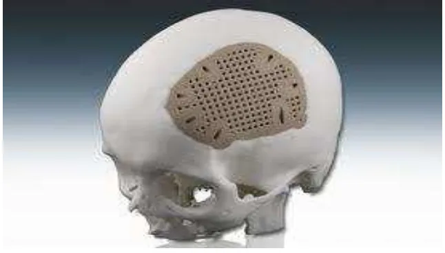
1.1 Example of a PEEK implant fabricated using milling process 1 2.1 Example of stand-alone anterior lumbar fusion cage 5
2.2 Example lumbar interbody fusion cage anterior 6
2.3 Example of Spinal Implant 8
2.4 Degrees of freedom in 5-axis machining 11
2.5 A normal to surface toolpath can usually not directly be machined 13
2.6 Direction Parallel 14
2.7 Contour Parallel 15
3.1 Process Planning (Flow Chart) 21
3.2 CAD Design 23
3.3 Part Operation Setting 24
3.4 Datum Reference Setting 24
3.5 Isoparametric Machining 25
3.6 Tool path strategies selection 26
3.7 Profile and face selection 26
3.8 Tooling setting 27
3.9 Feed rate setting 27
3.10 Macro management 28
3.11 Video simulation using tool path toolbar 28
3.12 simulation 29
3.13 cutting material according to a predetermined size using the bend saw 30
3.14 workpiece after cutting using bend saw 30
3.15 two holes drilled in the bottom surface 31
3.16 workpiece tied on the jig 31
3.17 Jig tied on CNC working table 32
3.18 Portable Surface Roughness Tester Mitutoyo 33
3.19 SurfTest calibrate surface 34
3.20 Coordinate Measuring Machine, WENZEL 3D/ LH 5.6.4 35
4.1 Point area for surface roughness test 38
x
4.3 Product back side view 42
4.4 Product front side view 42
4.5 Product upper side view 43
4.6 CAD back side view 43
4.7 CAD front side view 44
4.8 CAD upper Side View 44
4.9 Result for CMM testing 48
xi
LIST OF ABBREVIATIONS, SYMBOLS & NOMENCLATURE
CNC - Computer Numerical Control CAD - Computer Aided Design
CAM - Computer Aided Manufacturing
1
1.1Background of study
To meet the demands of the growing orthopaedic market and changing demographics of patients, implant design solutions are becoming increasingly sophisticated. Today, device manufactures are leveraging implantable plastics that process highperformance and customized properties, as they allow for greater design freedom and ultimately lead to improved applications. Polyetheretherketones (PEEK) is the most widely used long-tern implatable plastics in medical application. The increasing use of high performance plastics, composite materials and compounds can be seen in the development of a wide range of orthopedic application, including spinal fusion cages and plates,
artificial discs, acetabular cups, femoral stems and arthroscopic bone anchors and interference screws. In addition to meeting these general implant requirements. For this reason, only limited number of suitable biomaterials are available for the development of implantable orthopedic devices, and the emergence of new biomaterials is rare. Because of their biocompability and high performance, implatable-grade plastics have emerged as a leading biomaterial in the
developmentof orthopedic applications. These biomaterials are attractive for both their machenical properties and their associated processing technologies, which enable device manufacturers to tailor their characteristics to meet certain needs. The ability to tailor the characteristics of certain implantable-grade plastics means that device designers can consider factors other than the structural
2 substitution of the natural tissue. Physical characteristics such as the elastic modulus can be modified to recreate bone modulus. Mechanical properties such as the strength, wear resistance and impact performance of polymers and
composites can be comparable to metals and offer additional benefits. Since implantable-grade plastics are not metallic, they do not release metal ions into the body, which can trigger allergic ractions in certain patients. In addition to
reducing or eliminating allergic reactions, these materials also eliminate artifacs during post operative examination by traditional techniques such as X-ray, CT and MRI technology. Non-metallic materials also resist corrosion, leading to a longer implant life span. Polymers are also less dense than metals, have lower thermal conductivity and, in areas close to the translucent skin surface, provide better color aesthetics. In addition, oplymers present the ability to be surface modified with such coatings as hydroxyapatite or titanium, to aid secondary fixation or with chemical species as with bone morphogenic proteins (BMPs). Processing for some plastics can be easily scaled up to meet the increasing demand for product parts. Incorporating plastic technologies (for example, injection molding) means that the economics of production are viable on a larger scale, while complex shapes can be formed as required to aid device fabrication. However, often for prototype designs or shor production runs, it is not
economically viable to manufacture an injection molding tool. Under such circumstances, it is common to employ a machining process on the PEEK polymer materials to form the components.
3
1.2Problem Statement
Often for prototype designs or short production runs, it is not economically viable to manufacture an injection molding tool. Under such circumstances, it is common to machine the PEEK polymer materials to form components. However, because of the excellent physical properties and wear characteristics of these material can poses a challenging machining process.
Machining and finishing operation on polymeric materials are prone to propagating molded-in or residual stresses. Futher stress may be built up within the material by localized heating at the cutting point during machining process.
The best way to avoid adverse affects on the material’s biocompability is to machine dry. However, in many cases coolant is necessary to remove cutting heat that builds in the workpiece (PEEK doesn’t disspite heat the way metals do). Pure water serves as the best coolant because it is likely to affect
material biocompability.
As with all medical components, precautions must be taken to prevent surface contaminant of PEEK workpieces. One precautionary measure is to dedicate the machine tool, fixturing and tools to machining only that material. Some shops also insist their employees use gloves when handling PEEK to keep oils off the part surface.
Most of the machining processes for machining PEEK using a same cutting tool as machining metal. As the use of PEEK for medical implant devices is rising, success or failure in machining such an abrasive material depends largerly on the cutting tools.
Due to the customers’ high quality requirements and the huge price of the materials, particular care and precision are required during machining.
4
1.3 Objective
Both the difficulties and conventional cutting strategies for machining the PEEK materials cause to initiate this research. The objectives of this research are :
1. To investigate the effects of cutter path strategy (Lead and tilt,
Noraml to drive surface and Optimized lead) on machining
performance of PEEK material.
2. To propose the optimal cutter path strategy base on machining
4
2.1 Introduction
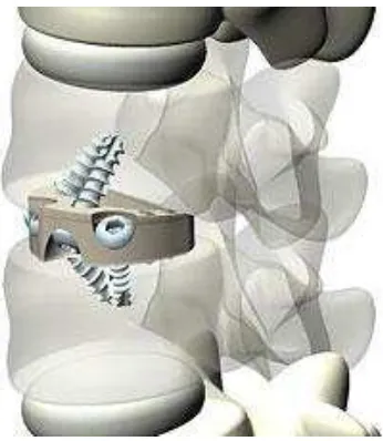
Innovation is the driver of industrial growth and doctors, consultants and surgeons, who are always seeking better treatment for their patients, are driving the orthopaedic implants market. Alternative material such as biocompatible polyetheretherketone has been increasingly employed as orthopaedic structural material such as stand-alone anterior lumbar fusion cage. The benefits of this implant offer include reduced operating time, better bone fusion, less shrinkage and loss of height, and improved spinal alignment. The implant can be inserted between vertebrae where it serves as a substitute for degenerative spinal discs. In first time spinal operations, it can simply be inserted into place and the grip-like tread on its surface and screws hold it in place.
5 Figure 2.1 Example of stand-alone anterior lumbar fusion cage
The Young’s Modulus of PEEK is similar to that of cortical bone, therefore, it offers more elasticity that metal. It can absorb energy, handle the normal weight of the body and minimise stress on adjacent levels. The material is also radiolucent
(transparent to X-rays) and thereby allows an improved view of the fusion mass that is taking place. However, to be able to offer X-ray (computer tomography or
6
2.2 Orthopaedics machining
Fabrication of orthopaedic implants required a combination of multidiscipline fields especially machining. In the case of machining, the ability to interact with the concept for new or modified implants is essential.
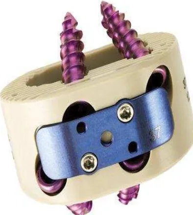
Figure 2.2 Example lumbar interbody fusion cage anterior
7 heated up at 10 deg C per hour until an equilibrium temperature of 250 deg C is reached. Then the components are allowed to cool at 10 deg C per hour until reaching below 140 deg C, and subsequently allowed to cool down to room temperature. In addition, the tight quality control and short lead time’s order of medical component make it more challenging. The production equipment used in the manufacturing process of orthopaedic implants involves computer numerical controlled (CNC) multi-axis machine tools that are able to produce high quality complex components in a consistent way from raw plastic and titanium material billets. Novel work holding techniques have been developed for two axis and three axis CNC machine tools to address the following issues:
The need to keep wastage of high cost materials to an absolute minimum
The complexity of the shapes being machined
The ability to handle components with unsual material characteristics
The need to maintain high accuracy at all times
Specialist applications that required standard machine tool technology to be adapted


