UNIVERSITI TEKNIKAL MALAYSIA MELAKA
ANALYZE THE EFFECT OF DEPTH OF CUT TOWARDS SURFACE ROUGHNESS IN MILLING
This report submitted in accordance with the requirements of the Universiti Teknikal Malaysia Melaka (UTeM) for the Bachelor Degree of Manufacturing Engineering
(Manufacturing Process) with Honours.
By
KASWADY BIN HUSMAN
DECLARATION
I hereby, declared this report entitled “Analyze the effect of depth of cut towards surface roughness in milling” is the results of my own research except as cited in the
references.
Signature : ………
Author’s Name : ………
APPROVAL
This report submitted to the Faculty of Manufacturing Engineering of UteM as a partial fulfillment of the requirements for the degree of Bachelor of Manufacturing Engineering (Manufacturing Process) with Honours. The member of the supervisory committee is as follow:
………. Project Supervisor
ABSTRACT
ABSTRAK
DEDICATION
Dedicated to my father, Husman Bin Hj. Abd. Karim and my mother, Rahmah Tan Bte
Abdullah.
ACKNOWLEDGEMENT
Many people have contributed to my learning experience at Universiti Teknikal Malaysia Melaka. I would like to thank my thesis advisor MR. SHAHIR and other lecturers, for her or his insight, thought provoking questions and guidance for my thesis.
I also would like to thank all the technicians in Phase B for the contribution for this thesis. They have spent valuable time to guide me to gather some information for this thesis. I also would like to thank the panels who have contributed directly or indirectly in this thesis.
LIST OF FIGURES
2.1 Up milling (Ronald and Denis, 2006) 7
2.2 Down milling (Ronald and Denis, 2006) 8
2.3 Milling entry angles (Ronald and Denis, 2006) 9
2.4 Variation in mean segment spacing as a function of cutting speed
(Davies, 2002) 15
2.5 A 23 two-level, full factorial design; factors X1, X2, X3 (Diniz, 2002) 23
3.1 Flowchart for methodology 28
3.2 Provided Mild Steel Dimension 29
3.3 Face mill cutting tool 36
3.4 Roughness Tester SJ-301 41
3.5 Dimension of Tester SJ-301 42
3.6 Standard terminology and symbols to describe surface finish. 42
3.7 Typical surface profiles produced by various machining and surface
finishing processes. 43
4.1 Machining process 48
4.2 Surface roughness test 49
4.3 Normal Probability Plot of the Effects (Aluminium 6061) 52
4.4 Pareto charts of Effect (Aluminium 6061) 54
4.5 Cube Plot (Data means) for Ra (Aluminium 6061) 55
4.6 Interaction Plot (Data means) for Ra (Aluminium 6061) 57
4.7 Main Effect Plot (data means) for Ra (Aluminium 6061) 59
4.8 Normal Probability plot of the Effects (mild steel 1030) 60
4.9 Pareto charts of Effect (mild steel 1030) 62
4.10 Cube Plot (Data means) for Ra (mild steel 1030) 63
4.11 Interaction Plot (Data means) for Ra (mild steel 1030) 65
LIST OF TABLES
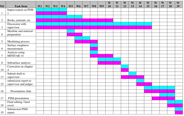
1.1 Gantt chart for PSM1 6
1.2 Gantt chart for PSM2 7
2.1 General application for cutting condition (Ronald and Denis, 2006) 16
2.2 Milling cutting speed for various material (Ronald and Denis, 2006) 17
2.3a High speed steel and carbide tool cutting parameters for various
SAE steel for aluminium workpiece (Arthur R Meyes, 2001) 18
2.3b Effects of cutting parameter on the surfaces finish on the surface machined.
(Mohammed et al., 2007) 19
2.4 A 23 two-level, full factorial design table showing runs in ‘Standard Order’
(Jiju, 2003) 24
3.1 DOE Matrix 31
3.2 Factorial Design for three parameter 32
3.3 MiniTab Worksheet 32
3.4 Cutting parameters for experiments 33
3.4 Data sheet design for surface roughness test for mild steel 1030 33
3.5 Data sheet design for surface roughness test for aluminium 6061 34
3.6 Data sheet design for surface roughness test for aluminium 6061 34
3.7 Gantt chart for PSM1 45
3.8 Gantt chart for PSM2 46
4.1 Mild steel 1030 Ra value for 8 samples 50
LIST OF ABBREVIATIONS, SYMBOLS, SPECIALIZED
NOMENCLATURE
PSI - Per square inch ft2 - feet square in2 - square inches
RPM - revolution per minute HSS - high speed steel CBN - cubic boron nitride
TABLE OF CONTENT
2.2 Milling Parameters 12
2.5.2 Benefits of DOE 23
2.5.3 Importance of DOE 24
2.5.4 Models of DOE 24
2.5.5 Full Fractional Design 26
2.5.6 Methodology for DOE 27
3.2 Material Selection 31
3.3 Design of Experiments (DOE) Analysis 31
3.3.1 MiniTab Software (release 14) 33
3.3.2 DOE Matrix 33
3.3.3 Factors 34
3.3.4 Data Sheet Design 35
3.4 Machining Process 37
3.4.1 Conventional Milling Machine Setup 38
3.4.2 Cutting Tool Type 38
3.4.3 Cutting Tool Material 39
3.4.4 Factor Affecting Choice of Tooling 39
3.4.5 Squaring 40
3.4.6 Proper machining 40
3.4.7 Identification of Process Parameters 41
3.5 Surface Roughness 42
3.5.1 Surface Roughness Analysis 42
3.5.2 Surface Roughness Equipment 43
3.5.4 Preparation of Standard Accessories 46
4. RESULT AND DISCUSSION 47
4.1 Introduction 47
4.1.1 Machining Process 48
4.1.2 Surface roughness test 49
4.2 Arranges of data 50
4.3 Analysis for Aluminium 6061 52
4.3.1 Identify the important effect 52
4.3.2 Identify the absolute value of the effects 54
4.3.3 Analyze response means 55
4.3.4 Identify the interaction for each pair of factors 56
4.3.5 Analyze the main effect 59
4.4 Analysis for Mild Steel 1030 60
4.4.1 Identify the important effect 60
4.4.2 Identify the absolute value of the effects 62
4.4.3 Analyze response means 63
4.4.4 Identify the interaction for each pair of factors 65
CHAPTER 1
INTRODUCTION
1.1
Background Analysis
Milling is the indicated process when needed to make all the other parts that cannot be made on the lathe. The demand of low tolerances and better quality products have forced manufacturing industry to continuously progress in quality control and machining technologies. Wang and Chang (2004) classified one of the fundamental metal cutting processes is end milling which is very often utilized for pocket milling in die and mould making.
Yang and Chen (2001) specified surface roughness is used as the critical quality indicator for the machined surfaces and has influence on several properties such as wear resistance, fatigue strength, coefficient of friction, lubrication, and wear rate and corrosion resistance of the machined parts. For this purpose, a number of experiments with four flute high-speed steel end mills were carried out on an aluminium material. Based on the data obtained a model was trained and tested, the system was proved capable of predicting the surface roughness with accuracy.
However, surface roughness is also affected by the cutter path strategies. For minimizing the surface roughness, the proper selection of cutter path strategies is very important. Different cutter paths in pocket milling operations can be used with end mills. Therefore, it is essential to investigate the effects of cutter path strategies in pocket milling. The aim of this study is, first, to investigate optimum cutting characteristics of DIN 1.2738 mould steel, which is one of the most commonly used plastic mould steel that noted by Thomas et al. (2000).
Hence the proper estimation of surface roughness has been the focus of study for several years. The surface roughness describes the geometry of the surface to be machined and combined with surface texture. The formation of surface roughness told by Benardos and Vosniakos (2003) that mechanism is very complicated and mainly depends on machining process.
Existing high-speed machining technology for rough milling is found on an unnecessary compromise. In order to increase two of the primary machining parameters spindle speed and federate two other primary parameters depth-of-cut and step over are reduced. While the machine certainly moves faster, material removal rates fall far short of what they could be. This is entirely due to the fact that all tool path algorithms since the inception of numerical control is fundamentally flawed, and the specialized high-speed milling algorithms that have emerged over the past decade contain the exact same flaws by Bernados and Vosniakos (2003).
machined products have been reported. These studies show that cutting conditions, the material properties of tool and work piece, as well as cutting process parameters (including cutting speed, depth of cut, feed rate, and tool geometry) significantly influence the surface finish of machined parts.
The obvious difference between turning and milling processes is that, in turning the main power is used to rotate an essentially cylindrical work piece with feed motions applied to the tool. But, in milling the main power rotates a cutting tool with the prismatic work piece undergoing feed motions. Milling cutting tools have many cutting edges and are more complicated than turning tools and each edge cuts only intermittently. The cost of the tools makes it prudent to remove metal more slowly and vibrations set up by the intermittent tool contacts reinforce this. The longer cutting times make, the non-productive time less significant noted by Thomas et al. (2000).
1.2 Problem Statement
1.3 Objectives
The objectives of this analysis are:
To analyze the effect of depth of cut on mild steel and aluminium To identify the suitable depth of cut to get fine surface roughness.
To study the effect of machining parameters on feed rate, depth of cut and cutting speed
1.4 Scope of Project
The scope of this study was limited to only 2 types of material. Those were mild steel 1030 and aluminium 6061. Design of experiments (DOE) methodologies used where full fractional designs will be used based on the 3 main factors. Normal probability, Pareto chart, cube plot, interaction plot, main effect plot and other tools will be constructed by using MiniTab software which will be applied for this study. The machining process was done using conventional milling machine and to get the result of surface roughness precisely where it used the apparatus in metrology lab. The method used for milling was climb milling where face mill cutting tool with 6 insert used. Face mill was preferred because that type of cutting was easy to find at the lab. There were two value of depth of cut used for each material in gaining the good result.
1.5 Report Outline
Chapter 2 presents the literature review on surface roughness in milling with DOE concepts and what is the correlation about surface roughness and depth of cut in milling process.
Chapter 3 describes the DOE concepts and description of the methodology used in this analysis.
Chapter 4 will display the result and data collection from machining process and the experiment done. In this chapter, all collected data will be analyzed stage by stage.
1.6 Gantt Chart
Table 1.1: Gantt chart for PSM1
CHAPTER 2
LITERATURE REVIEW
2.1 Milling Features
Milling is a machining process for generating machined surfaces by removing a predetermined amount of material progressively from the work piece. The milling process employs relative motion between the work piece and the rotating cutting tool to generate the required surfaces. In some applications, the work piece is stationary, and the cutting tool moves, whereas in others, the cutting tool and the work piece are moved in relation to each other and to the machine. A characteristic feature of the milling process is that each tooth of the cutting tool takes a portion of the stock in the form of small, individual chips.
Figure 2.1: Up milling (Ronald and Denis, 2006).
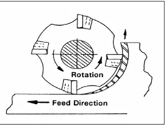
Figure 2.2: Down milling (Ronald and Denis, 2006).
Ronald and Denis (2006) noted that climb milling or down milling is now the preferred method of milling with advanced cutting tool materials such as carbides, cermets and CBN as in Figure 2.2. The insert enters the cut with some chip load and proceeds to produce a chip that thins as it progresses toward the end of the cut. This allows the heat generated in the cutting process to dissipate into the chip. The cutting tool will rotate anticlockwise and the work piece will come from right side. The cutting tool will climb the work piece along the machining process. The user will be able to avoid the chips by standing in front of the machine and at the right side.