DUAL BAND MICROSTRIP FILTER
WAN MOHD AZLAN BIN WAN MUSTAPHA
i
DUAL BAND MICROSTRIP FILTER
WAN MOHD AZLAN BIN WAN MUSTAPHA
This Report Is Submitted In Partial Fulfilment of Requirement for the Bachelor Degree of Electronic Engineering (Wireless Communication) With Honours
Fakulti Kejuruteraan Elektronik dan Kejuruteraan Komputer Universiti Teknikal Malaysia Melaka
v
vi
ACKNOWLEDGEMENT
vii
ABSTRACT
This project proposed a novel dual-band microstrip parallel-coupled SIR-BPF based on the traditional single-band coupled theory. The scope of this project presented analyze, simulation, fabricate, and measurement for parallel-coupled SIR-BPF design. Parallel-Coupled SIR-BPF is one of the popular methods to design dual-band microstrip filter because of the simplicity and compactness. The filter is designed at center frequencies of 1.3 GHz and 2.8 GHz bandwidth 25 MHz and 55 MHz. this frequency is presenting for wireless video transmitter application and Worldwide Interoperability for
Microwave Access (WiMAX). There are several step to design this filter that including
by determine filter specification, order of filter, bandpass filter prototype elements, bandpass transformation, physical dimensions calculations (width, spacing, length), and wavelength guide. The simulation of the dual-band microstrip filter will be done using Advance Design System 2008 software. The fabrication process will do on FR4 substrate by using etching process. Improvement technique will be introduced to get better response for scattering parameter (S11 and S21). Simulation results of this dual
band filter shows that the values of S21 are -0.004 dB for low frequency and -0.006 dB
viii
ABSTRAK
ix
CONTENTS
CHAPTER TITLE PAGE
PROJECT TITLE
PSM STATUS VERIFICATION FORM DECLARATION
SUPERVISOR VERIFICATION FORM DEDICATION
ACKNOWLEDGEMENT ABSTRACT
ABSTRAK CONTENT
LIST OF TABLES LIST OF FIGURES
LIST OF ABBREVIATIONS
i ii iii iv v vi vii viii ix xii xiii xv
I INTRODUCTION 1
1.1 PROJECT BACKGROUND 1
1.2 PROBLEMS STATEMENTS 4
1.3 OBJECTIVES 4
1.4 SCOPE OF PROJECT 4
x
II LITERATURE REVIEW 6
2.1 FILTER 6
2.1.1 Types Of Filter 7
2.2 BANDPASS FILTER 9
2.2.1 Parallel Coupled Line Filter 9
2.3 FREQUENCY RESPONSE OF FILTERS 11
2.3.1 Maximally Flat Or Butterworth Prototype 11
2.3.2 Chebyshev Response 12
2.3.3 Bessel 13
2.3.4 Elliptic Filter 13
2.4 MICROSTRIP 14
2.4.1 Overview Of Microstrip 15
2.4.2 The Advantages And Disadvantages Of Microstrip 15
2.5 DUAL BAND MICROSTRIP FILTER 16
2.5.1 Twin-Filter Method 16
2.5.2 Notch-Adding Method 16
2.5.3 Stepped Impedance Resonators (Sirs) 17
2.5.4 Modified Sirs 18
2.6 FEED STRUCTURE 19
2.6.1 Tapped-Line Structure 19
2.6.2 Coupled-Line Structure 21
2.7 SCATTERING PARAMETERS 22
2.7.1 Scattering Parameters For A Two Port Network 22
III METHODOLOGY 27
xi
3.2 SPECIFICATION OF DESIGN 30
3.2.1 Filter Structure 31
3.3 DESIGN AND SIMULATION 36
3.4 FILTER ANALYSIS 37
3.5 FABRICATE THE FILTER DESIGN AND TESTING 37
IV RESULT AND ANALYSIS 40
V
4.1 PARALLEL-COUPLED SIR-BPF PROTOTYPE 4.2 SIMULATION RESULTS
4.2.1 Before Analyze Results (Values From Calculation)
4.2.2 After Analyze Results 4.3 MEASUREMENT RESULTS 4.4 COMPARISON
CONCLUSION AND RECOMMENDATION
5.1 CONCLUSION
5.2 RECOMMENDATION
41 42 42 43 51 54 56 56 57
REFERENCES 73
xii
LIST OF TABLE
NUMBER TITLE PAGE
3.1 Specifications and associated design parameters of the dual-band
microstrip filter
30
3.2 3.3 4.1 4.2 4.3 4.4 4.5
FR4 substrate properties
Dimension of parallel-coupled SIR-BPF Center frequency: 1.3 GHz (low frequency) Center frequency: 2.8 GHz (high frequency) Center frequency: 1.3 GHz (low frequency) Center frequency: 2.8 GHz (high frequency)
Comparison between simulation results and measurement results
xiii
LIST OF FIGURE
NUMBER
2.1
TITLE
Basic filter response
PAGE
8
2.2 General layout of parallel coupled filter 9
2.3 Equivalent circuit of a parallel coupled line filter 10
2.4 Frequency responses of various filters 11
2.5 Chebyshev lowpass filter 12
2.6 Elliptic Function Response 13
2.7 Microstrip transmission line 14
2.8 Coupling Path 18
2.9 Proposed filter structure 19
2.10 Geometry of a tapped-line feeding 20
2.11 2.12
Filter design with Tapped Line Feeding Coupled-line feeding
20 21
2.13 Two port network 22
2.14 Two port network with root power variables 24
2.15 Two port network parameters 25
xiv 3.2 3.3 3.4 3.5 3.6 3.7 3.8 4.1 4.2 4.3 4.4 4.5 4.6 4.7 4.8 4.9 4.10
Geometry of a sir
Dimensions of parallel-coupled SIR-BPF Parallel-coupled SIR-BPF layout
Parallel-coupled SIR-BPF schematic Flowchart of the fabrication process
PNA-X Network Analyzer (Agilent technologies)
Fabricated dual band microstrip filter by using parallel-coupled SIR-BPF method
Front view of parallel-coupled SIR-BPF
(a) Frequency response for S21 using calculation dimensions (b) Frequency response for S11 using calculation dimensions (a) Frequency response for S21
(b) Frequency response for S11
(a) Dual-band frequency response (S21) (b) Dual-band frequency response (S11) (a) Simulation result of S21 before change l1 (b) Simulation result of S11 before change l1 (a) Simulation result of S21 after reducing l1 (b) Simulation result of S11 after reducing l1 (a) Simulation result of S21 after optimization (b) Simulation result of S11 after optimization
Measurement results for centre frequencies using PNA-X Network Analyzer (Agilent technologies)
Measurement results for bandwidth using PNA-X Network Analyzer (Agilent technologies)
(a) Measurement result for S21 (b) Measurement result for S11
xv
LIST OF ABBREVIATIONS
BPF - Bandpass Filter
SIR - Step Impedance Resonator
S-PARAMETER - Scattering Parameter
ADS - Advance Design System
mm - millimeter
GHz - Giga Hertz
MHz - Mega Hertz
CHAPTER I
INTRODUCTION
1.1 Project Background
dual-2 band function [1]. The first approach requires a switching circuit, increasing insertion loss and power consumption, whereas the second approach needs dual-band components such as dual-band filters.
The microstrip filter is popular in dual-band filters design because it has a planar
structure, and is easy to connect with other devices. Dual-band microstrip filter design can be classified into four types.
The first method can be called twin-filter method. This type of dual-band microstrip filter is obtained by combining two individual single-band filters via a common input/output port [2–5]. This type of dual-band filter is easy to realize, because signals of the two bands pass through different resonators, allowing the two individual single-band filters to be designed independently.
3
The third method, which is often favored for its compactness, is to employ stepped impedance resonators (SIRs) [16]. For convenience, this approach may be called the SIR method. The electrical lengths and impedance ratio are used to control the fundamental and spurious resonance frequencies to meet the central frequencies of the two bands. Therefore a single set of resonators can introduce dual-band responses. In addition to the central frequency, important specifications of a filter include the type of frequency response, bandwidth and passband ripple. These characteristics are determined by the external quality factors and the coupling coefficients when using traditional coupled filter theory. Thus, the key point to developing a SIR dual-band filter is finding appropriate physical parameters to satisfy the required external quality factors and coupling coefficients at both bands simultaneously [17–22]. Since two physical parameters are necessary to obtain every desired external quality factor or coupling coefficient, two-dimensional searching or trial and error is often used. Obtaining the required values of physical control parameters is time consuming. Besides, it does not guarantee suitable values that meet the specifications.
4
1.2 Problems Statements
A low cost of manufacturing and design in microwave subsystem is the most highlighted issues today. That’s why the proposed filter design used Parallel-Coupled SIR-BPF method because notch-filter method generally required large size for the great quantity of resonators which means the cost in order to produce the filter is higher than using the proposed method. Parallel-Coupled SIR-BPF method is easy to realize, because signals of the two bands pass through different resonators, allowing the two individual single-band filters to be designed independently. SIRs method is more compact and required fewer resonators than other methods. Furthermore, the problem of the demand for high performance, high efficiency, low loss and excellent reproducibility microwave always high will be overcome by use the coupled lines which generate the transmission zero.
1.3 Objectives
The objective of this project is to design a dual band microstrip filter using Parallel-Coupled SIR-BPF method and FR4 as substrate. Furthermore, this filter is target to operate at 1.3 GHz (Wireless Video Transmitter) and 2.8 GHz (WiMAX).
1.4 Scope Of Project
The scopes of this project are:
Design and Fabricate the dual band filter by using Parallel-Coupled SIR-BPF
5
Analyze the performance of the filter from s parameter (S11 and S21) by using
Advance Design System (ADS) software.
Do parametric analysis is performed on the structure to determine the optimum
dimensions to obtain the desired frequency response.
Finally, assure the filter to be operates at 1.3 GHz and 2.8 GHz.
1.5 Thesis Outline
CHAPTER II
LITERATURE REVIEW
This chapter discuss about the fundamental of the dual band filter and the reasons for the chosen of the filter design method.
2.1 Filter
7 applications for both military and commercial markets. Several major developmental categories in filter technology are included performance improvement, development of CAD tools, full wave analysis, new structures and configurations, and advanced materials and associated technologies. Advanced materials/technologies such as high-temperature superconductor substrates, micromachining, multilayer monolithic, low temperature co-fired ceramic, and liquid-crystal polymer are commonly used in the development of advance filters. Some recent applications of filters include dual-band communications, such as wireless local area networks and ultra wideband communication and imaging [24].
Low Pass filters can be designed from the classical lumped element low-pass prototype circuits and may either be fabricated in lumped element form or transformed into equivalent transmission line networks. Band-pass filters require precise transmission characteristics that allow a desired band of signals to pass through the two-port network. Thus, between a transmitter and the transmitting antenna, a band filter may be used to attenuate unwanted signals and harmonic components that may cause interference to other users of the electromagnetic spectrum. Conversely, between an antenna and a receiver, a band pass filter will reject out-of-band signals that may cause interference within the receiver, especially if they are at a high signal level in comparison with the desired signals.
2.1.1 Types Of Filter
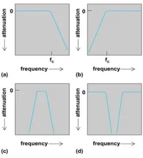
Filters may be classified in a number of ways. An example of one such classification is reflective versus dissipative. In a reflective filter, signal rejection is achieved by reflecting the incident power, while in a dissipative filter; the rejected signal is dissipated internally in the filter. In practice, reflecting filter is used in most applications. The most conventional description of a filter is by its frequency characteristic such as lowpass, bandpass, bandstop, or highpass. Typical frequency
8 displays zero insertion loss, constant group delay over the desired pass band, and
infinite rejection elsewhere. However, in practice, filters deviate from these
[image:24.612.185.474.176.496.2]characteristics and the parameters in the introduction above are a good measure of performance [25].
Figure 2.1 Basic filter response (a) Lowpass, (b) Highpass,