TORQUE HYSTERESIS CONTROLLER FOR BRUSHLESS DC MOTOR
DRIVES
Ahmad Faiz Noor Azam , Mustafa Manap, Auzani Jidin, Norhazilina Bahari, Hatta Jopri, Abdul Rahim bin Abdullah
Department Of Power Electronics Drives, Faculty of Electrical Engineering, Universiti Teknikal Malaysia Melaka (UTeM) Hang Tuah Jaya, 76100 Durian Tunggal, Malacca, Malaysia
Abstract—The presence of the commutator and brushes in a dc machine enforce severe limitations on its voltage and current ratings, means that the output power capability of a dc machine is restricted. The mechanical commutator in a dc machine limits its high speed capabilities. Both the brushes and commutator of a dc machine require regular maintenance. In addition, dc machines are prone to sparking and cannot be normally used in explosive atmosphere. The dust produced by brush wear, makes the dc machine undesirable for use in certain industries like the semiconductor or food industries. Thus, to overcome this problem BLDC machine is proposed due to its advantages over the conventional dc machine. The torque hysteresis controller is presented as the technique chosen to control the phase current and torque of the BLDC machine. This method used to replace the voltage control in BLDC machine. Voltage control is conventional methods used but have a very high current overshoot, by using torque hysteresis controller it will provide current protection which is the value of current and torque will stay within certain limits around with reference value.
Keywords-components; Brushless DC motor; hall effect; torque hysteresis controller
I. INTRODUCTION
Conventional dc motors are highly efficient and their characteristics make it reliable for use in many applications. However, the only drawback is that it uses commutator and brushes that require frequent maintenance and cannot be performed at dirty and explosive environment and at very high speed operating conditions [1]. When the functions of commutator and brushes were replaced by solid-state switches, maintenance-free motor were developed. These types of motors are now known as brushless dc motors. Brushless dc (BLDC) motors are in fact a type of permanent magnet synchronous motors. It is driven by dc voltage and the current commutation is done by solid state switches. BLDC motor implements the basic operating principles of DC motor operation but with a difference by placing the permanent magnet in the rotor and coils in the stator. The coil windings are electrically separate from each other which allow it to be turn on and off in a sequence
that creates a rotating magnetic field. The rotor position needs to be determined so that excitation of the stator field always leads the permanent magnet field to produce torque. The commutation instants are determined by the rotor position and the position of the rotor is detected either by position sensors or by sensorless techniques. The signals from Hall Effect sensors that usually used in BLDC motor need to decode to determine the shaft and energize the appropriate stator windings.
BLDC motors are available in many different power ratings, which vary from very small motor as used in hard disk drives to large motor used in electric vehicles. BLDC motor attracts much interest due to its high efficiency, high power factor, high power density, compactness, high torque, simple control and lower maintenance. The power circuit components that are required to convert from alternating current to direct current provide the basis for variable-speed drive, making BLDC motors well-suited for applications that require speed control over a wide operating range. The permanent magnets used in BLDC motor helps to keep the inertia low. The BLDC motor generates less heat because there is no current flow in the rotor thus allowing efficient heat dissipation from the BLDC motor’s wound stator to the outer metallic housing.
The simulation of a torque hysteresis controller for BLDC motor drive system is developed using ‘Matlab/Simulink’. The simulation circuit includes all realistic components of the drive system. The concept of torque hysteresis controller is basically similar to hysteresis current controller because the torque is proportional to the current. A comparative study associated with hysteresis and PWM techniques in current controllers has been made. By comparing these techniques, hysteresis current controller is chosen considering its easy implementation, quick response, maximum current limit and insensitive to load parameter variations.
II. CONSTRUCTIONOFBLDCMOTOR
17 Dec 2012
same frequency, hence eliminating the slip which is normally seen in induction machine. BLDC motor has two primary pats which is rotor (rotating part), stator (stationary part) and permanent magnet of the rotor. There are two basic rotor designs which is inner rotor and the other one is outer rotor.
For the inner rotor design, the stator winding surround the rotor and are fixed at motor housing. The advantages of the design are the ability to dissipate heat thus directly impacts its ability to generate torque and its lower inertia. For the outer rotor design, the winding are located in the core of the motor. The rotor magnets surround the stator windings and acts as an insulator, reducing the rate of heat dissipation from the motor. This design operates at lower duty cycles or at lower rated current. The advantage of this design is relatively low cogging torque. The winding slots are built into the stator and changing magnetic field is provided by the current polarity changes in the slot windings. The change of current polarity must be in accordance to the rotor magnetic field, which requires the position of the rotor. Hall effect sensors are fixed on the stator to provide this information. Solid state switches are used for current commutation which eliminates the need of brushes.
There are two types of back-emf that a BLCD motor can generate which are trapezoidal and sinusoidal waveforms.[2] The back-emf is determined by the manner in which windings are placed in the stator, either concentrated or distributed windings. Concentrated windings produce a trapezoidal back-emf while distributed windings result in a sinusoidal back-emf.
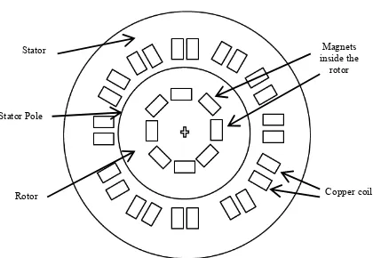
For the permanent magnet rotor, there are also two designs which are practiced. The first design place the permanent magnet onto the surface of the rotor, see figure 1. By placing the magnet onto the rotor reduces the manufacturing time but during high speed condition there is possibilities that the magnet might fly off the rotor. For the other design the magnets are inserted beneath the surface of the rotor, see Figure 2. This practice requires additional machining of the rotor to create the slots for the magnets which in the end increased the manufacturing time and cost. However, the advantage is that the motor can be operated at very high speed conditions without the danger of magnet failure.
Figure 1.BLDC motor cross section for surface mounted PM’s
Figure 2.BLDC motor cross section for innermounted PM’s
The three phase BLDC motor is operated in a two-phases-on fashion which is mean the two phases that produce the highest torque are energized while the third phase is off, see Figure 3. The two phases are energized depends on the rotor position. The signals from the position sensors produce a three digit number that changes every 60 degree (electrical degrees). Current commutation is done by a six-step inverter.
Figure 3.BLDC motor cross section and phase energizing sequence.
The power electronic converter is necessary to operate the BLDC machine. The converter is three phases DC to AC converter and it consists of six solid state semiconductor switches. Mosfets and IGBT are the most common types of switches used. In lower power application, mosfets are preferred over IGBT. The power electronic inverter must be capable of applying positive, negative and zero voltage across the motor phase terminals. Each drive phase consists of one motor terminal driven high, one motor terminal driven low, and one motor terminal floating [2].
Magnets inside the
rotor
Copper coil Stator
Stator Pole
Rotor
Stator
Stator Pole
Rotor
ap el Magnets on the rotor
Figure 4.Three-Phase DC to AC inverter. III. MODELLINGOFBLDCMACHINES
Mathematical modeling of a BLDC motor can be derived similar to DC machines where there are two equivalent circuits, i.e electrical and mechanical equations. Figure 5 shows the basic blocks of BLDC motor that contains three phase stator circuit and mechanical part. The main difference compare to DC machines is the construction of the machine where it has three phase windings at the stator (with n number of poles) and the rotor equipped with permanent magnet which is positioned at the center of the motor by the bearing. The rotor is not electrically connected to the stator thus preventing arcing phenomena which cause carbon to be produce hence making insulation failure.
Figure 5.Three phase Brushless DC machine equivalent circuit and mechanical model.
For simplification, the electrical model is expressed for one phase of stator winding, e.g. phase k(k=a,bor c) as given by (1).
ݒሺݐሻ ൌ ݅୩ ୩ௗௗ௧ೖሺݐሻ ݁ሺt) (1)
where,
vkn(t)• = instantaneous of k-phase voltage
ik(t) = instantaneous of k-phase current
ek(t) = instantaneous of k-phase back-emf voltage
Rk =k-phase resistance
Lk =k-phase inductance
On the other hand, the mechanical model of BLDC machine actually represents the production of torque as given by (2).
ܶሺݐሻ ൌ ݀߱ሺݐሻ݀ݐ ߱ሺݐሻ ܶሺݐሻ (2)
where,
ω(t)• = rotor angular velocity
B• = viscous friction
J = moment of inertia
TL = load torque
It should be noted that the production of torque is the summation of the torque produced for each phase;
ܶሺݐሻ ൌ ܶǡሺݐሻ
ୀǡୟ୬ୢ
(3)
The productions of torque and back-emf voltage for each phase are calculated as;
ܶǡሺݐሻ ൌ ݅ሺݐሻǤ ்݇ǡሺߐሻ (4)
݁ሺݐሻ ൌ ݇௩ǡሺߐሻǤ ߱(t) (5)
where, the torque factor kT,k(ϴ) can be assumed equivalent to the back-emf voltage factor kV,k(ϴ). The angular velocity (ωe) is multiplication of rotor angular
velocity and number of poles of the machine, i.e. ω x
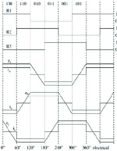
number of poles. For trapezoidal operated in BLDC motor, the kT,k(ϴ)and kV,k(ϴ)are not constant as opposed to the constant field operated in brushes DC motor. Given the rotor position (ϴ), these factors can be simply obtained using piece-wise normalized trapezoidal function as illustrated in Fig. 5.
From Fig. 5, it can be noticed that each phase winding is conducted in sequence for 1200per one cycle of period to carry either positive or negative constant current. The conduction of each phase winding is determined by the rotor position where the position can be known from hall effect sensors that provides three digitized output. The generation of three digitized outputs (i.e. H1,H2and H3) from the sensor according to the rotor position can be also described in Fig. 5.
17 Dec 2012 motor speed, the motor is turned off if the speed reaches a certain level above the reference speed and turned back on when the speed falls below a certain level below the reference speed. Nevertheless, due to lack of coordination among individual hysteresis controller of three phase, very high switching frequency at lower modulation index may happen[3].
The drawbacks of the hysteresis band control technique are the high and uncontrolled switching frequencies when a narrow hysteresis band is used and large ripples when the hysteresis band is wider [4]. The uncertain switching frequency make filtering of acoustic and electromagnetic noise become difficult [5]. The switching method used here is the soft chopping method which is only the upper switch is turned on and off while the lower switch is left on. This method produces less torque ripple and less switching losses than the hard chopping method. Only torque control and speed control is implemented here. The reason is that if position control were to be implemented in the same way as the torque and the position control, it would only be possible by constantly reversing the rotor speed so that the rotor angle would stay within the hysteresis band.
It is desirable to provide current limitation and fast torque dynamic control for many electric drive applications. A simple method that can offer these requirements is the use of torque hysteresis controller (THC) technique. Figure 6 shows the structure of torque hysteresis controller for BLDC motor
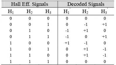
The control of torque can be established by controlling the three-phase current at its reference such that it will satisfy the equations (3) and (4). As shown by Fig. 6, the motor currents need to be controlled satisfying to their currents are based on the torque demand (i.e. Iref= Te,ref x G1) and decoded signals (H1’, H2’ and H3’) which are derived from the Hall Effect signals (H1, H2and H3) as given in Table 1.
TABLE 1 Derivation of Decoded Signals based on Hall Effect Signals hysteresis comparator, which is responsible to produce appropriate switching status to be fed into the inverter, either to increase or decrease the phase current such that its error (or current ripple) is restricted within the hysteresis band (HB). In such a way, the reference current for each phase will have the same pattern waveform with the respective decoded signals. .
Figure 7.Structure of Torque Hysteresis Controller (THC) drive for BLDC motor.
V. EXPERIMENTAL RESULTS
The brushless DC motor drive system has been realized and tested in laboratory. The experimental setup consists of hysteresis current control, accurate speed and position information, a secure three phase DC/AC inverter, digital signal processor and an appropriately size BLDC machine and load. The control and motor parameters values used for this experiment are shown in Table 2.
TABLE 2 Control and Motor Parameters Values Control System
Flux linkage established by magnets 0.175 V.s
Torque constant 1.4 Nm/A
Moment of inertia 0.04 Kg.m2
Friction factor 0.005 Nms
Pole pairs 4
Figure 8. Motor currents are controlled such that it follows their references which were generated based on the hall effect signals
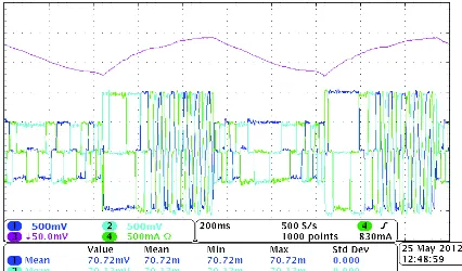
Figure 9 shows the speed and current output waveforms of the motor. It can be observed as the speed decreases (during motor braking) the frequency of the current waveforms decreases and as the speed increase (during motor acceleration) the frequency of the current waveforms increases. Another phenomenon that can be observed is the phase sequence of the current. If the speed of the motor is above 0, the phases of the current are as follows, (cyan, blue and green) while during negative speed, the phases of the current are as follows (green, blue and cyan)
Figure 9.Experimental results showing output waveforms of speed and currents.
VI. CONCLUSIONS
This paper has presented the modelling and experimental result of torque hysteresis controller for BLDC motor. Torque hysteresis controller has been applied to a BLDC drive and the results shows that the current ripple stays within the hysteresis band as defined by the controller.
ACKNOWLEDGMENT
The authors would like to thank the Universiti Teknikal Malaysia Melaka (UTeM) for providing the grant for this research.
REFERENCES
[1] Lefley, P., L. Petkovska, and G. Cvetkovski. Optimization of the design parameters of an asymmetric brushless DC motor for cogging torque minimization in Power Electronics and Applications (EPE 2011), Proceeding of the 2011-14th European Conference on 2011.
[2] Hendershot, J.R and T. Miller. Design of Brushless Permanent-Magnet Motors. Oxford: Magna Physics Publications & Oxford Science Publication, 1994.
[3] Ching-Tsai, P. and C. Ting-Yu, An improved hysteresis current controller for reducing switching frequency. Power Electronics, IEEE Transactions on, 1994. 9(1): p. 97-104.
[4] KS Low M.F Rahman and K.W Lim. Approaches to the Control of Torque and Current in Brushless Dc Drive,2002. [5] Texas Instruments Incorporated. DSP Solutions for BLDC
Motors,1997.
[6] Mayer, J.S. and O. Wasynczuk, Analysis and modelling of a single-phase brushless DC motor drive system. Energy Conversion, IEEE Transactions on, 1989. 4(3): p. 473-479. [7] P.C Sen. Principles of Electric Machine and Power Electronics,
John Wiley,1997. .
[8] Hart, Daniel W. Introduction of Power Electronic, Prentice hall,2002.
[9] El-Shakawi, A Mohamed. Fundamental of Motor Drives, Books/Cole Publishing Company,2000.