Smart
System
for
Aircraft
Passenger
Neck
Support
CHEEFAI
TAN
• Under the sponsorship of the Ministry of Higher Education, Malaysia
• Under the sponsorship of Universiti Teknikal Malaysia Melaka (UTeM),
Malaysia
• Under the funding by the European Commission DG H.3 Research,
Aeronautics Unit under the 6th Framework Programme SEAT, under
contract Number: AST5‐CT‐2006‐030958
A catalogue record is available from the Eindhoven University of Technology
Library
ISBN: 978‐90‐386‐2392‐4
NUR: 964
©
CheeFai Tan, 2010
All rights reserved. No part of this publication may be reproduced or transmitted
in any form or by any means, electronic or mechanical, including photocopying,
recording or any information storage or retrieval system, without permission from
the author.
Smart
System
for
Aircraft
Passenger
Neck
Support
PROEFONTWERP
ter verkrijging van de graad van doctor aan de
Technische Universiteit Eindhoven, op gezag van de
rector magnificus, prof.dr.ir. C.J. van Duijn, voor een
commissie aangewezen door het College voor
Promoties in het openbaar te verdedigen
op dinsdag 14 december 2010 om 16.00 uur
door
CheeFai Tan
geboren te Kuala Lumpur, Maleisië
prof.dr. G.W.M. Rauterberg
en
prof.dr. R. Nakatsu
Copromotor:
dr. W. Chen
Specially dedicated to my beloved parents and family in Malaysia, my lovely wife
(SiawThien ONG) and my son (ShengRay TAN) for the love and support given.
This study was supported by:
• Ministry of Higher Education, Malaysia
• Universiti Teknikal Malaysia Melaka, Malaysia (UTeM)
• the European Commission DG H.3 Research, Aeronautics Unit under the
6th Framework Programme SEAT, under contract Number: AST5‐CT‐2006‐
030958
I owe my gratitude to all people who have made this thesis possible and because
of whom my PhD study has been one that I will cherish forever.
Firstly, I would like to thank my main supervisor, Professor Dr. Matthias
Rauterberg for giving me an invaluable opportunity to work on this challenging
project over the past four years. It has been a great pleasure to work with and
learn from such an extraordinary professor. I would also like to thank my second
supervisor, Professor Dr. Ryohei Nakatsu and my daily supervisor, Dr. Wei Chen
for their generous help and constant support during my PhD study. Their valuable
advices helped to keep my research on track. Thanks are due to Professor Dr. Ir.
Hermie Hermans, Professor Dr. Ir. Loe Feijs and Dr. Jos van Haaren for agreeing to
serve on my doctoral committee and for sparing their invaluable time reviewing
my manuscript and for their comments. The expertise from each of them
provided me with a unique perspective.
My colleagues: Ellen, Hao, Frank, Jun, Emilia, Rene, Peter, Christoph, Geert van de
Boomen, Geert van Langereis, Sibracht, Chet, Sjriek, Omar, Richard Foolen, Julma
Braat, Leon, Sietse and others at Department of Industrial Design have enriched
my PhD life in many ways as well. My thanks also go to my friends Qiang Zeng,
SyeLoong, LeeChin, Asim, Carin, Desmond and others for their support of my work.
I like to thank Marinka de Groot from BGZ Wegvervoer, Netherlands for her
assistance on Dutch truck driver body discomfort survey and Mr. Fan for the
construction work of aircraft cabin simulator. Special thanks to Ellen, Geert van
HG 2.44.
I would like to specially thank for the scholarship that I have received from UTeM
and Ministry of Higher Education, Malaysia. I appreciated Professor Dr. Md. Razali
bin Ayob, Dean of Faculty of Mechanical Engineering, Universiti Teknikal Malaysia
Melaka and Professor Dr. Md. Radzai bin Said for their support of my PhD study. I
also appreciated Professor Datuk Dr. Ahmad Yusoff bin Hassan, Vice Chancellor of
UTeM and Professor Dato’ Dr. Mohamad Kadim bin Suadi, Deputy Vice Chancellor
(Research and Innovation) of UTeM, for their motivation during the visit to
Eindhoven University of Technology in year 2009.
Last but not least, I wish to thank my beloved parents, sisters and brother in
Malaysia, my dearest wife, SiawThien and son, ShengRay. It is their love,
encouragement and support that made my PhD successful.
CheeFai Tan
October 2010, Eindhoven
Acknowledgement vi
Contents viii
List of Figures xi
List of Tables xiii
Acronyms xv
1 INTRODUCTION 1
1.1 Overview. . . 2
1.1.1 Seating Comfort and Discomfort during Air Travel. . . 2
1.1.2 Study on Seating Comfort and Discomfort. . . 3
1.2 Research Objective. . . 5
1.3 Organization of the Thesis. . . 5
1.4 Contribution of the Thesis. . . 6
2 STATE OF THE ART 11 2.1 Introduction. . . 12
2.2 Background. . . 13
2.2.1 Seating Comfort and Discomfort. . . 13
2.2.2 Aircraft Passenger Seat. . . 15
2.2.3 Objectifying and Subjectifying of Seat (Dis)Comfort. . . 18
2.2.4 Summary and Conclusions. . . 27
2.3 Questionnaire on Seating Comfort and Discomfort. . . 27
2.3.1 Introduction. . . 27
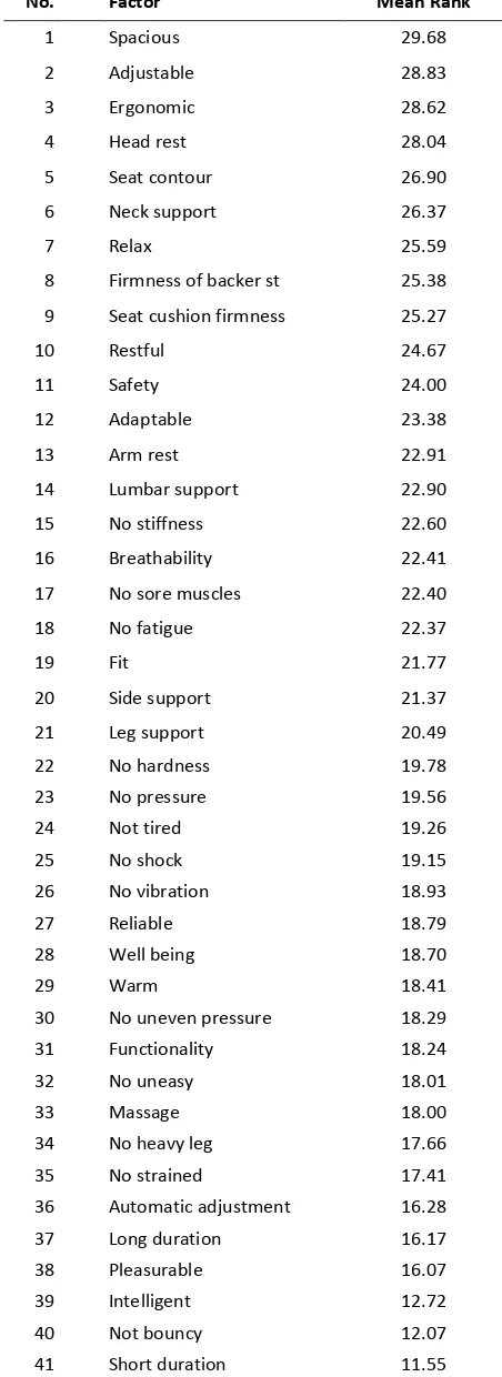
2.3.2 Identifying Factors of Seating Comfort. . . 28
2.3.3 Survey on Body Discomfort for Truck Driver during Travel. . . 33
2.3.4 Survey of Body Discomfort for Economy Class Aircraft Passenger. . . 40
2.3.5 Survey of Relationship between Seat Location and Sitting Posture. . . 50
2.3.6 Summary and Conclusions. . . 54
2.4 Overall Conclusions. . . 55
3 DEVELOPMENT OF A SMART NECK SUPPORT SYSTEM 57 3.1 Introduction. . . 58
3.2 Existing Neck Support during Travel. . . 59
3.2.1 Travel Type Neck Support. . . 59
3.2.2 Long Distance Commercial Vehicle Passenger Seat with Neck Support. . . 60
3.3 A Smart Neck Support System. . . 64
3.3.1 The Architecture of a Smart Neck Support System. . . 65
3.3.2 System Design. . . 66
3.3.3 Mechanical Modeling of Airbag. . . 73
3.4 The Total Design of a Smart Neck Support System. . . 75
3.5 Prototype. . . 83
3.5.1 Hardware. . . 84
3.5.2 Software. . . 86
3.6 Recommendation for Future Work. . . 87
3.7 Summary. . . 88
4 DESIGN OF AN AIRCRAFT CABIN SIMULATOR 89 4.1 Introduction. . . 90
4.2 Related Work. . . 91
4.2.1 The Current Application of Aircraft Cabin Simulator. . . 91
4.3 Design Methodology of Aircraft Cabin Simulator. . . 95
4.3.1 Design Process. . . 95
4.3.2 Preliminary Design. . . 97
4.3.3 Conceptual Design. . . 98
4.4 Concept Selection. . . 108
4.4.1 Concept Generation. . . 108
4.4.2 Concept Evaluation and Selection. . . 109
4.5 Final Design and Implementation. . . 110
4.5.1 Motion Platform. . . 116
4.6 Cost Evaluation. . . 118
4.7 Validation of Aircraft Cabin Simulator. . . 119
4.7.1 Methods. . . 119
4.7.2 Results. . . 124
4.7.3 Discussion and Conclusions. . . 125
4.8 Recommendation for Future Work. . . 126
4.9 Summary. . . 126
5 EVALUATION OF A SMART NECK SUPPORT SYSTEM 129 5.1 Introduction. . . 130
5.2 Neck Muscle and Electromyography Measurement. . . 130
5.3 Calibration Experiment. . . 132
5.3.1 Hypotheses. . . 132
5.3.2 Methods. . . 134
5.3.3 Results. . . 142
5.3.4 Discussion and Conclusions. . . 152
5.4 Validation Experiment. . . 153
5.4.1 Research Question. . . 153
5.4.2 Methods. . . 154
5.4.3 Results. . . 160
5.4.4 Discussion and Conclusions. . . 164
5.5 Summary. . . 165
6 CONCLUSION 167 6.1 Overview. . . 168
6.5 Overall Conclusions. . . 172
BIBLIOGRAPHY 175
APPENDICES 191
A.1 Questionnaire on Seating Comfort Factors. . . 192
A.2 The Means and Standard Deviation of Comfort Factors. . . 194
A.3 Truck Driver’s Seat Uncomfortable Survey. . . 195
A.4 The Mean Ranks, Means and Standard Deviation for Each Truck Driver Body Part After One Hour and After Five Hours of Travel. . . . .
200
A.5 Economy Class Aircraft Seat Survey (Woman). . . 201
A.6 Economy Class Aircraft Seat Survey (Man). . . 206
A.7 The Mean Ranks, Means and Standard Deviation for Economy Class Aircraft Passenger Body Part After One Hour and After Five Hours of Travel. . . .
211
A.8 Economy Class Aircraft Seat Survey (Before Experiment). . . 212
A.9 Economy Class Aircraft Seat Survey (After Experiment). . . 214
LIST OF PUBLICATIONS 217
SUMMARY 221
CURRICULUM VITAE 225
2.1 Hypothetical model of discomfort and comfort (Diagram reprinted from Zhang and Helander, 2006). . . .
15 2.2 Air cushion system of Swiss Air first class and business class seat (Photograph reprinted
from Swiss Air, 2010). . . . 16
2.3 The Cozy Suite (Photograph reprinted from Thompson Solutions, 2010). . . 17
2.4 The Comfort Line 3610 economy class seat (Photograph reprinted from RECARO, 2009). . . . . 17 2.5 The Skycouch (Photograph reprinted from Dailymail, 2010). . . . 18
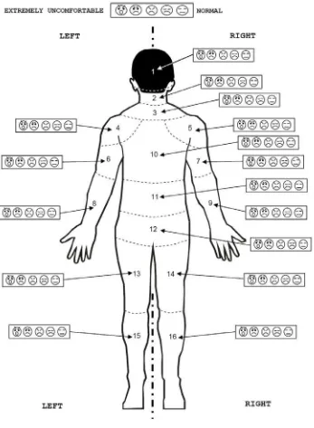
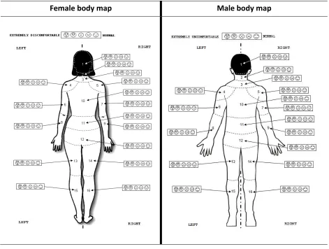
2.6 The body mapping for comfort and discomfort rating (Photograph reprinted from Kyung et al., 2008). . . . 26 2.7 Evaluation of seat comfort based on seat mapping (Photograph reprinted from Inagaki et al., 2000). . . . 26 2.8 Body map and scales for body discomfort evaluation. . . 36
2.9 The sitting location of observer and observed subjects. . . 51
3.1 The luxury coach passenger seat with neck support (Photograph reprinted from Five Star Tours, 2010) . . . . 61 3.2 The German train ICE passenger seat with neck support. . . 61
3.3 The French train Thalys passenger seat with neck support (Photograph reprinted from Raileurope, 2010). . . . 62 3.4 The Eurostar passenger seat with neck support (Photograph reprinted from Bembridge, 2007). . . . 62 3.5 The Cathay Pacific Airlines economy class aircraft seat with built‐in neck support (Photograph reprinted from Cathay Pacific, 2010). . . . 63 3.6 The Qantas Airline economy class aircraft seat with neck support (Photograph reprinted from Travelhouseuk’s Travel Blog, 2010). . . . 63 3.7 Feedback loop for smart neck support system. . . 64
3.8 The simplified architecture of a smart neck support system. . . 65
3.9 State transition of SnS2. . . 66
3.10 Schematic of ‘Standby State’. . . 67
3.11 Schematic of ‘Passenger Presence State’. . . 68
3.12 Schematic of ‘Right Support State’. . . 68
3.13 The schematic of example initial position and supported position for right airbag. . . 69
3.14 Schematic of ‘Left Support State’. . . 69
3.15 The schematic of example initial position and supported position for left airbag. . . 70
3.16 Flowchart for the neck support state transitions when the passenger is touching the airbag. . . 72
3.17 The schematic of the forces that act on the single airbag. . . 74
3.18 The design process of SnS2. . . 76
3.19 The 3D isometric view of SnS2 prototype. . . 81
3.20 The exploded view of SnS2 prototype. . . 81
3.21 The first SnS2 functional prototype. . . 82
3.22 The installation of the final SnS2 functional prototype to the economy class seat in the aircraft cabin simulator. . . . 82 3.23 Three SNS2 prototypes embedded in the economy class aircraft seat. . . 83
3.24 Block diagram of information flow. . . 84
3.25 The pneumatic control unit. . . 85
3.26 The pneumatic system for the airbag. . . 86
4.3 Schematic of aircraft cabin environment (Figure reprinted from Weber et al., 2004). . . 93
4.4 Emergency trainer of Austrian Airlines (left) and test rig at BRE (right) (Photographs reprinted from Mellert et al., 2008). . . . 94 4.5 The cabin mock‐up (Photograph reprinted from Zhang et al., 2009). . . 94
4.6 The mockup of the Boeing 767‐300 aircraft cabin (Photograph reprinted from Wang et al., 2008). . . . 95 4.7 The architecture of the aircraft cabin simulator design process. . . 96
4.8 The objective tree of the aircraft cabin simulator. . . 99
4.9 The wall with extended aircraft cabin view. . . 101
4.10 The concept two. . . 108
4.11 The overall setup of the aircraft cabin simulator in the simulation lab. . . 111
4.12 The final design of cabin light from top view (not to scale). . . 111
4.13 Business class section. . . 112
4.14 Economy class section. . . 113
4.15 Galley. . . 114
4.16 Lavatory. . . 114
4.17 External view of the aircraft cabin simulator at projection side. . . 115
4.18 Overall internal view of the aircraft cabin simulator. . . 115
4.19 The schematic of the motion platform. . . 116
4.20 The schematic of the motion platform system. . . 117
4.21 The video recording inside the aircraft cabin simulator. . . 122
4.22 Procedure of the flight simulation. . . 123
4.23 The floor plan for emergency evacuation and the location of safety equipment. . . 124
5.1 The SCM muscle (Photograph reprinted from Wikipedia, 2010a). . . 131
5.2 The headset (Aart et al., 2007; Aart et al.,2008). . . 135
5.3 A participant attached with EMG electrodes, wearing the headset with laser beam, sitting inside the head angle measurement apparatus and leaning against SnS2 prototype. . . . 136 5.4 MP150 Biopac systems with electrodes and cables. . . 137
5.5 The schematic of defined angles for the head rotation angle apparatus in top view. . . 138
5.6 The SCM muscle with EMG electrodes. . . 139
5.7 A participant inside the head rotation angle measurement apparatus (45 degree condition). . . 140
5.8 The box plots of normalized EMG value for both test conditions split by head rotation angles for each of participant seperately. . . . 145 5.9 The box plot of normalized EMG value split by time intervals and neck support conditions for head rotation angle R30°. . . . 147 5.10 The box plot of normalized EMG value split by head rotation angles for both neck support conditions. . . . 150 5.11 The box plot of normalized EMG value over SCM muscle for both rotation directions split by neck support conditions. . . . 151 5.12 The installation of three SnS2 prototypes in the aircraft cabin simulator for validation experiment with the treatment group. . . . 155 5.13 The experimental setup of participants for the treatment group in the aircraft cabin simulator. . . . 158 5.14 The box plot of comfort factors for the control group and the treatment group. . . 162 5.15 The box plot of normalized EMG value for the participants in relation to both neck conditions
(before support with SnS2 and after supported with SnS2
). . . . 163
2.1 Overview of different objective measurement methods for seat comfort and discomfort. . . 19
2.2 Various pressure measurement techniques. . . 20
2.3 Objective measurement techniques for posture analysis. . . 21
2.4 The objective measurement methods for vibration analysis. . . 22
2.5 The objective measurement methods for temperature and humidity. . . 22
2.6 CAE measurement methods for seat development. . . 23
2.7 Various objective measurement methods for physiological analysis. . . 24
2.8 The mean ranks for comfort factors. . . . 31
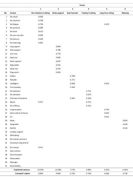
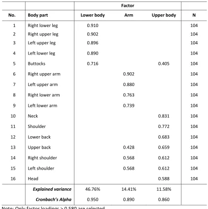
2.9 Factor loading of the comfort factors. . . 32
2.10 The five point Likert scale. . . 35
2.11 Demographic details for truck driver. . . 37
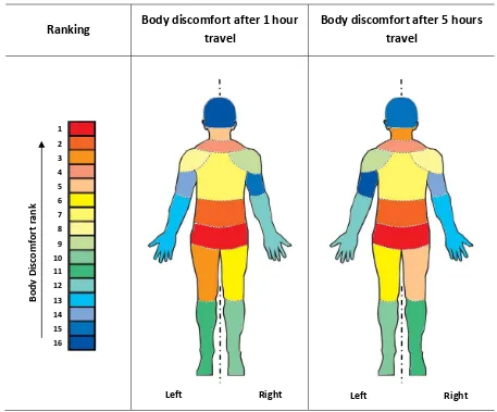
2.12 Body discomfort ranking of truck drivers after one hour and after five hours of travel. . . 39
2.13 Body map and scales for body discomfort evaluation. . . 42
2.14 Demographic details for 104 aircraft passengers who participated in the study. . . 43
2.15 Results of factor analysis of body part discomfort after one hour travel. . . 45
2.16 Results of factor analysis of body part discomfort after five hours travel. . . 47
2.17 Body discomfort ranking of aircraft passengers after one hour and after five hours of travel. . . 48
2.18 The coding of sitting posture for observation purpose. . . 52
3.1 The description of the product requirement for SnS2. . . 77
3.2 The morphology chart for SnS2 airbag prototype. . . 78
3.3 Weighted objective evaluation of SnS2 prototype concepts. . . 80
4.1 The requirements for the aircraft cabin simulator. . . 97
4.2 Morphological chart of the economy class section. . . 100
4.3 Morphological chart of the business class section. . . 102
4.4 Morphological chart of the galley section. . . 103
4.5 Morphological chart of the lavatory section. . . 104
4.6 Morphological chart of the projection section. . . 106
4.7 Morphological chart of the motion platform. . . 107
4.8 Evaluation of the overall simulator concept using the weighted objective method. . . 110
4.9 The specification of the airbag. . . 116
4.10 The comparison between different options regarding hardware, functionality and cost. . . 118
4.11 Means (M) and standard deviations (SD) of presence questionnaire. . . 125
5.1 Demographic profile of participants. . . 134
5.2 Descriptive statistics of questionnaire result. . . 143
5.3 The test for within‐subjects effects for neck support condition (with support and without support). . . . 144 5.4 The normalized SCM EMG value related to neck support condition. . . 144
5.5 The test for within‐subjects effects between SCM EMG value and time interval. . . 146
5.6 The normalized EMG value over time interval. . . 147
5.7 The test for within‐subjects effects between SCM EMG value and head rotation angles. . . 149
5.8 The normalized SCM EMG value in different head rotation angles related to both neck support conditions. . . . 149 5.9 The test for within‐subjects effects between SCM muscles. . . 151
5.10 The normalized SCM EMG value for both rotation directions related to neck support conditions. . . . 151 5.11 Demographic details of participants. . . 154
5.12 The questionnaire scores for the two groups (control and treatment). . . 160
AC Alternating Current
Ag Silver Metal
AgCl Silver Chloride
ANOVA Analysis of Variance
BMI Body Mass Index
CAD Computer‐Aided Design
CAE Computer‐Aided Engineering
CCTV Closed Circuit Television
CE Concurrent Engineering
DC Direct Current
ECG Electrocardiography
EEG Electroencephalography
EMG Electromyography
ICSP In‐Circuit Serial Programming
LA Left Airbag
M Mean
MR Mean Rank
MVC Maximal Voluntary Contraction
N Number of Data Points
PCA Principal Component Analysis
PDS Product Design Specification
RA Right Airbag
SCM Sternocleidomastoid
SD Standard Deviation
SEAT Smart tEchnologies for Stress free Air Travel
SnS2 Smart Neck Support System
SVGA Super Video Graphics Array
TD Total Design
UART Universal Asynchronous Receiver/Transmitter
USB Universal Serial Bus
CHAPTER
1
INTRODUCTION
1.1 OVERVIEW
Travel by air is becoming a common activity to people due to the low cost flight
and accessibility for individuals of all ages. With the growing number of aircraft
passenger, it is important to provide a comfortable flight. The passenger may
experience different levels of psychological stress during the air travel process,
such as unfamiliarity with the airport departure process, food served during flight,
different environment conditions in the aircraft cabin, seat position, flight
duration, and seat design. Besides, the changes of time zone during air travel may
cause jet lag and affect the passenger’s health. Airline companies are already
trying to improve the comfort of the aircraft passenger (Brundrett, 2001). But the
latest aircraft such as Airbus A380 is now flying non‐stop for 15 hours and long
haul air travel is not a natural human activity. Many people experience different
levels of physiological and psychological discomfort during air travel. Discomfort
during air travel may endanger the aircraft passenger’s health
(Kalogeropoulos, 1998; Brundrett, 2001; World Health Organization, 2007).
1.1.1 Seating Comfort and Discomfort during Air Travel
Comfort is an important requirement of today’s aircraft passenger. Hertzberg
(1972) describes comfort as ‘the absence of discomfort or the state of no
awareness of a feeling’. The term ‘seat comfort’ is defined as the short‐term
effect of a seat to the human body (Kolich, 2008). Comfort is a subjective feeling
that relates to physiological and psychological aspects of humans (Shen and
Parsons, 1997). The subjective comfort feeling of aircraft passengers is affected by
the aircraft features and the cabin environment. During air travel, the aircraft
passenger’s seat is an important feature to provide comfortable seating
conditions to the passenger. The aircraft seat also is a place where the passenger
spends most of his/her time during air travel. The airline industry is a highly
competitive industry in which the airline companies always try to maximize their
profit by maximizing the number of seats (Quigley et al., 2001). The increase of
seat numbers causes a reduction of seating space for passengers, especially in
economy class seats (Hinninghofen and Enck, 2006). Brundrett (2001) describes
degree of the seat, close seat pitch and insufficient leg room. In some cases, the
close seat pitch causes the aircraft passenger to experience discomfort in
different body parts, for example leg numbness, deep vein thrombosis, neck pain,
shoulder pain and back pain (Brundrett, 2001; Dumur et al., 2004).
Quigley et al. (2001) found that aircraft passengers complained about discomfort
at lower back, buttocks and neck during air travel. They also found that the
comfort of the aircraft passenger is affected by flight duration. During long haul
flight, the aircraft passenger feels discomfort and is unable to have a good sleep.
Alexander (2005) found that some economy class aircraft passengers only sleep
for about three hours during overnight air travel. The seating discomfort can
affect the aircraft passenger during air travel. Therefore, we are interested in the
primary question related to aircraft passenger seating discomfort as follows:
• How can we contribute to reduce economy class aircraft passenger seating
discomfort during air travel?
1.1.2 Study on Seating Comfort and Discomfort
From the literature review about seating comfort and discomfort, we found that
the research was mainly related to ground vehicle seats and office seats. The
research on ground vehicles such as cars and trucks can be found in various
research areas e.g. seat pressure study (Boileau and Rakheja, 1990;
Gyi et al., 1998), seat comfort modeling (Kolich, 2008; Runkle, 1994), posture
study (Kolich, 2008), seat vibration study (van Niekerk et al., 2003), ergonomic
study (Alem and Strawn, 2003; Chang et al., 1996), and seat thermal study (Fung,
1995; Cengiz and Barbalik, 1996). The research on office seats can be found in the
work by De Looze (2003), Zhang (2000) and Helander and Zhang (1997). There are
a few publications related to aircraft seat research, for example, seat design
(Nadadur and Parkinsin, 2009; Teo, 1999), thermal comfort (Bartels, 2003),
cushion design (Petit et al., 1999), and pilot seat design (Lusted et al., 1994;
Goossens et al., 2000). There is also information related to aircraft passenger
seats in published patents, for example, aircraft passenger seat
(Schonenberg and Konig, 2002; Papaopannou et al., 1997), cushion
The small amount of public accessible research on aircraft passenger seating
comfort and discomfort may be due to the competitiveness and confidentiality of
the airline industry.
In the current development of aircraft seat, InNova (Sutter and Acuna, 2003) has
created a seat design called ‘the bubble’. ‘The bubble’ design increases the
passenger’s perception of space by moving the hand luggage compartment to
underneath the seat. On the other hand, B/E Aerospace developed a moving seat
called ‘ICON seating’ (Elliott, 2006). The movable seat surface enables the
passenger to change into back sleep and side sleep. Besides, side support wings
on the seat bottom can be adjusted to provide leg support in a side sleep posture.
The advantage of ICON seating is that it enables the passengers to control their
comfort condition and to provide personal space. Lantal Textiles (2006) has
developed a pneumatic cushions comfort system for an aircraft seat in which the
conventional foams are replaced by an air chamber. The aircraft passengers can
adjust the air chamber pressure manually based on their preferences. The
following questions related to the study of aircraft passenger seating comfort and
discomfort need to be answered:
• Will a smart neck support system be able to reduce the economy class
aircraft passenger’s neck discomfort during air travel?
• How can we contribute to the development of a smart system reducing the
economy class aircraft passenger’s seating discomfort during air travel?
In this thesis, we answer these questions and investigate how to contribute to
reduce neck discomfort for economy class aircraft passenger during air travel.
1.2 RESEARCH OBJECTIVE
The research presented in this thesis has the following three objectives:
• To discover the body back discomfort of economy class aircraft passenger.
Subjective methods such as questionnaires will be used to survey body back
discomfort. The results from the study should be able to provide input and
requirements for the development of a smart system.
• To develop a smart neck support system (SnS2) to reduce neck discomfort
for economy class aircraft passengers during air travel.
The designed smart neck support system (SnS2) is expected to reduce neck
discomfort of economy class aircraft passengers in an adaptive manner. The
system should be validated through subjective and objective
measurements.
• To evaluate the design in an aircraft cabin simulator.
An aircraft cabin simulator should be used for the validation of the
developed smart neck support system (SnS2). The simulator should be
capable to simulate the economy class section environment.
1.3 ORGANIZATION OF THE THESIS
This thesis consists of six chapters.
Chapter 1: Introduction provides an overview of the thesis, scope and motivation
of the research question. It is followed by research objectives and the outline of
the thesis.
Chapter 2: State of the Art describes the literature research study on recent
development of the vehicle seat design which is available in current literature and
products. Subsequently, questionnaires on seating comfort and discomfort are
aircraft seat, body back discomfort among truck drivers and economy class
aircraft passengers during travel, as well as the relationship between seat location
and sitting posture.
Chapter 3: Development of a Smart Neck Support System is to reduce the
sternocleidomastoid neck muscle stress for aircraft passenger during air travel.
The development process of a smart neck support system (SnS2) is described.
Chapter 4: Design of an Aircraft Cabin Simulator is to validate the developed
smart neck support system for economy class aircraft passenger seat in the
aircraft economy class cabin‐like environment. An aircraft cabin simulator is a
testbed that is designed and built to conduct the validation experiment for a
smart neck support system. The development of an aircraft cabin simulator is
discussed in this chapter.
Chapter 5: Evaluation of a Smart Neck Support System is conducted with two
experiments, namely a calibration experiment and a validation experiment. The
calibration experiment is designed to measure the sternocleidomastoid muscle
stress of participants in relation to head rotation angle, time and neck support
conditions. The validation experiment is designed to validate a smart neck
support system (SnS2) in an aircraft cabin simulator. The details of both
experiments are described in this chapter.
Chapter 6: Conclusion summarizes the main results of this thesis.
1.4 CONTRIBUTION OF THE THESIS
We consider the problem of how to develop a smart system to reduce the seating
discomfort of the aircraft passenger during air travel. The following contributions
are made in this thesis.
Chapter 2
• We study the state of the art on seating comfort and discomfort (e.g. office
chair, car, truck and aircraft).
• We describe the objective and subjective methods to measure the seating
comfort and discomfort.
• We determine the comfort factors related to the economy class aircraft
passenger seat.
• We define the body back discomfort level for Dutch truck driver after one
hour and after five hours of travel.
• We define the body back discomfort level for economy class aircraft
passenger after one hour and after five hours of travel.
• We identify the relationship between seat location and sitting posture for
economy class aircraft passengers.
The key results of Chapter 2 have been published in:
Tan, C.F., Delbressine, F. and Rauterberg, M. 2007. Vehicle Seat Design: State of
the Art and Recent Development. Proceedings of 3rd World Engineering Congress
2007 (WEC2007), Penang, Malaysia, pp. 51‐61.
Tan, C.F., Delbressine, F., Chen, W. and Rauterberg, M. 2008. Subjective and
objective measurement for comfortable truck driver seat. 9th International
Symposium on Advanced Vehicle Control (AVEC2008), Kobe, Japan, pp. 851‐856.
Tan, C.F., Chen, W. and Rauterberg, M. 2009. Self‐reported seat discomfort
amongst economy class aircraft passenger in the Netherlands. World Congress on
Bioengineering 2009 (WACBE2009), Hong Kong Polytechnic University, Hong
Kong, China, pp. 211.
Tan, C.F. Chen, W. and Rauterberg, M. 2010. Seat discomfort of Dutch truck
driver: a survey study and analysis. SAE World Congress, Detroit, Michigan, paper
Chapter 3
• We propose a framework for a smart neck support system (SnS2) to reduce
the sternocleidomastoid muscle stress adaptively in an automatic manner.
• We develop a smart neck support system (SnS2).
The key results of Chapter 3 have been published in:
Tan, C.F., Chen, W., Kimman, F. and Rauterberg, M. 2009. Sleeping posture
analysis of economy class aircraft seat. World Congress on Engineering 2009,
London, UK, pp. 532‐535.
Tan, C.F. Chen, W. and Rauterberg, M. 2009. Development of adaptive aircraft
passenger seat system for comfort improvement. Proceedings of International
Conference for Technical Postgraduates, Kuala Lumpur, Malaysia, paper no. CC02‐
05.
Tan, C.F. Chen, W., Hao Liu and Rauterberg, M. 2009. Adaptive framework and
user preference modeling for economy class aircraft passenger seat. 2009 Third
UKSim European Symposium on Computer Modeling and Simulation, Greece,
Athens, pp. 66‐69.
Chapter 4
• We develop an aircraft cabin simulator to validate the developed smart
neck support system (SnS2).
The key results of Chapter 4 have been published in:
Tan, C.F. Chen, W. and Rauterberg, M. 2009. Interactive aircraft cabin testbed for
stress‐free air travel system experiment: an innovative concurrent design
approach. International Conference on Advances in Mechanical Engineering
ICAME 2009, Shah Alam, Malaysia, p. 137.
Tan, C.F. Chen, W. and Rauterberg, M. 2009.Design of aircraft cabin testbed for
stress free air travel experiment. 5th International Conference on Planning and
Design, Tainan City, Taiwan, p. 157.
Tan, C.F. Chen, W. and Rauterberg, M. 2009. Creative thinking of design and
redesign on SEAT aircraft cabin testbed: a case study. 14th International
Conference on Thinking, Kuala Lumpur, Malaysia, pp. 122‐131.
Tan, C.F. Chen, W. and Rauterberg, M. 2010. Total design of low cost aircraft cabin
simulator. Design 2010, Cavtat, Croatia, pp. 1721‐1728.
Chapter 5
• We design a head angle measurement apparatus to define the head
rotation angle.
• We define the relationship between sternocleidomastoid
electromyography value with head rotation angle, time,
sternocleidomastoid muscle and neck support conditions.
• We validate a smart neck support system (SnS2) in our aircraft cabin
simulator.
The key results of Chapter 5 have been published in:
Tan, C.F., Chen, W. and Rauterberg, M. 2010. The Relationship of head rotation
angle and SCM EMG value for the development of AnS2. World Congress on
Engineering (WCE2010), London, U.K., pp. 2082‐2085.
Tan, C.F. Chen, W. and Rauterberg, M. 2010. An approach to study the sitting
position and neck discomfort of economy class aircraft passenger during air travel.
International Conference on Applied Human Factors and Ergonomics (AHFE2010),
Miami, Florida, USA, Chapter 40, pp. 376‐382.
Tan, C.F., Chen, W. and Rauterberg, M. 2010. Experimental design for
on Methods and Techniques in Behavioral research (Measuring Behavior 2010),
Eindhoven, the Netherlands, pp. 44‐47.
CHAPTER
2
STATE
OF
THE
ART
2.1 INTRODUCTION
This chapter1 describes the state of the art related to the issues of seating comfort
and discomfort, current aircraft seat, measurement methods and survey on
seating comfort and discomfort. The state of the art was acquired through
literature review of research in the field of seating comfort. The involvement of
the author in the development of the aircraft cabin simulator for European
Project SEAT (Smart tEchnologies for Stress free Air Travel) motivated the author
to focus on the aircraft related product research. The section begins with the
seating comfort and discomfort and its relationship with air travel. Next, the
current aircraft seats are described. Subsequently, objective and subjective
measurements are discussed to assess comfort and discomfort. It is followed by
four surveys studying the seating comfort and discomfort.
1
This chapter is partially based on the following articles:
Tan, C.F., Delbressine, F. and Rauterberg, M. 2007. Vehicle Seat Design: State of the Art and
Recent Development. Proceedings of 3rd World Engineering Congress 2007 (WEC2007), Penang,
Malaysia, pp. 51‐61.
Tan, C.F., Delbressine, F., Chen, W. and Rauterberg, M. 2008. Subjective and objective
measurement for comfortable truck driver seat. 9th International Symposium on Advanced
Vehicle Control (AVEC2008), Kobe, Japan, pp. 851‐856.
Tan, C.F., Chen, W. and Rauterberg, M. 2009. Self‐reported seat discomfort amongst economy
class aircraft passenger in the Netherlands. World Congress on Bioengineering 2009
(WACBE2009), Hong Kong Polytechnic University, Hong Kong, China, pp. 211.
Tan, C.F. Chen, W. and Rauterberg, M. 2010. Seat discomfort of Dutch truck driver: a survey
2.2 BACKGROUND
This section describes the study in relation to issues of seating comfort and
discomfort, vehicle seat, and different measurement methods to quantify seating
comfort and discomfort. The background study was acquired through literature
review of research in the field of seating comfort. The section begins with the
seating comfort and discomfort and its relationship with vehicle seat e.g. car,
truck and office. Next, the current aircraft seat is described. Subsequently,
objective and subjective measurements are discussed to assess comfort and
discomfort.
2.2.1 Seating Comfort and Discomfort
The Cambridge Advanced Learner’s dictionary (2008) defined comfort as ‘a
pleasant feeling of being relaxed and free from pain’. Seat comfort is determined
subjectively because the user justifies the seat comfort based on his/her
subjective experience in using the seat (Runkle, 1994). Helander (2003) stressed
that a good ergonomic design of the seat is a precondition for seat comfort. De
Looze et al. (2003) described comfort as affected by different factors such as
physical, physiological and psychological factors. Helander and Zhang (1997)
noted that there is a difference between seating comfort and discomfort in office
chairs. They described how comfort is related to emotional aspects like feeling
safe and luxury. Discomfort is more related to physical aspects like feeling
pressure and muscle pain.
The Theoretical Model of Comfort and Discomfort
There is no widely agreeable definition of comfort and discomfort in sitting
(De Looze et al., 2003). Comfort, as described by Shen and Vertiz (1997), is
defined as ‘lack of discomfort’. One of the definitions of comfort by
Dumur et al. (2004) is ‘the pleasant and satisfying feeling of being physically or
mentally free from pain and suffering, or something that provides this feeling’.
According to the ‘European Union Legislation for Drivers and Promote’
(Euroactiv, 2007), the weekly driving time for truck drivers shall not exceed 56
hours. Commercial trucks are designed to transport heavy loads over long
distances. The long hours of sitting during driving can cause risks of buttocks and
body back discomfort (Floyd and Roberts, 1958). The study by Adler et al. (2006)
showed that the driver’s posture is not static and changes over time. The study
also showed that drivers change their postures to avoid mechanical load and
ischemia of tissue. Discomfort feeling, as described by Helander and Zhang (1997),
is mainly affected by biomechanical factors and fatigue.
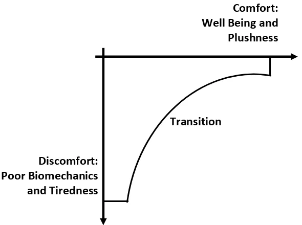
Zhang and Helander (1996) presented a model that illustrates the interaction of
comfort and discomfort as shown in Figure 2.1. The model shows the transition of
comfort and discomfort. When the person performs a task for a longer period
while sitting, the discomfort factor will increase. In contrast, when the person
feels well being during sitting, the comfort factor will increase.
Kolich (2008) described that seat designers are required to satisfy different
cultural background and perception of seat comfort for different people. Kolich
(2008) described that in general Western Europeans prefer firmer seats than
North Americans. Posture as described by Kolich (2008) is the most important
factor for individual seating comfort. Demographics and anthropometry also
contribute to the individual factors. The seat factors include stiffness, geometry,
contour, breathability and styling. For the social factors, the seat comfort may be
affected by vehicle nameplate as well as the car selling price. Lastly, the car
factors are influenced by seat height/eye position, pedal position, head/knee
room and transmission type. Runkle (1994) described the Lear’s seat comfort
benchmarking methodology which incorporates and integrates four tools into a
single comprehensive seat comfort analysis, such as market research studies,
benchmarking studies, body pressure distribution analyses and human factors
studies of anthropometric data. The results concluded that good aesthetics,
well‐design and comfort are more important than physical parameters in seat
design.
Figure 2.1 Hypothetical models of discomfort and comfort.
(Diagram reprinted from Zhang and Helander, 2006)
2.2.2 Aircraft Passenger Seat
The aviation industry is a highly competitive industry. In the past, the aviation
industry focused on the business class and premiere class sections that enable the
higher profit margin than the economy class section. Nowadays, the profit
margins of the aviation industry have been undercut by the low cost airlines. The
booming business relationship between Asia and Europe strongly encourages
business long haul air travel between regions. To secure the market share, the
airline companies offer attractive service and hardware to ensure a comfortable
air travel for aircraft passengers. The aircraft seat manufacturers also play an
important role to design and manufacture aircraft seat for comfortable air travel.
Current Aircraft Passenger Seat
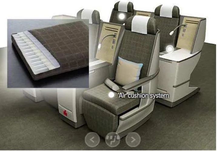
A Swiss company designed an air chamber to replace the conventional foam of
aircraft seat. The company claimed that the air chamber cushion is able to adapt
to the seating positions of aircraft passenger (Lantal Textiles, 2010a). Since year
2009, all business class and first class seats of the SWISS airline for long‐haul fleet
Transition
Discomfort: Poor Biomechanics
and Tiredness
Comfort: Well Being and
[image:31.612.163.458.67.287.2]were installed with the air cushion system (Figure 2.2). Four seat companies,
namely B/E Aerospace, Contour, ZIM Flugsitz and Recaro, implemented Lantal’s
air cushion system in their aircraft seats (Lantal Textiles, 2010b). The Lantal’s
pneumatic comfort system is a passive control system, where passenger needs to
adjust the hardness of the air chamber manually.
Figure 2.2 Air cushion system of Swiss Air first class and business class seat.
(Photograph reprinted from Swiss Air, 2010)
Thompson Solutions developed a new economy seat, the Cozy Suite (Figure 2.3).
The purpose of this seat is to help aircraft passengers to sleep. The seat has a
contoured shoulder area and wider knee space between seats
(James and Kington, 2008). The new seat design claims to increase 14% of
economy class passenger seats in Boeing B767‐400. The Cozy Suite focuses on
legroom, armrests, airline revenues, seat quantity, ease of egress, personal space
and dedicated sleeping area (Thompson Aero Seating, 2009).
[image:32.612.128.486.194.443.2]
Figure 2.3 The Cozy Suite.
(Photograph reprinted from Thompson Solutions, 2010)
B/E Aerospace exhibited its economy class ‘Spectrum’ passenger seat. The seat
platform is 10% lighter in weight and provides over 14% additional space. The
developed seat includes a sculpted Crytalflex back support system and meets the
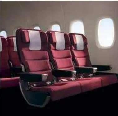
2009 Head Injury Criteria requirements. RECARO Aircraft Seating presented a new
version of its single‐beam Comfort Line 3610 economy class seat (Figure 2.4).
The seat increases the legroom even at a relatively short seat pitch. The seat has
comfort features including kinematics that improve the seating angle, a flexible
headrest, a foot net and ultra‐thin lightweight aluminum backrest with comfort
netting (James and Kington, 2008).
Figure 2.4 The Comfort Line 3610 economy class seat (Photograph reprinted from
[image:33.612.210.400.505.692.2]Air New Zealand introduced the ‘Skycouch’ (Figure 2.5), a lie‐flat economy class
and premium economy class seat in year 2010. The ‘Skycouch’ is a lie‐flat seat
which consist a row of three seats. The seat can be changed to a kid playground
or a flat surface for passengers to relax and sleep (Air New Zealand, 2010).
Figure 2.5 The Skycouch (Photograph reprinted from Dailymail, 2010).
2.2.3 Objectifying and Subjectifying of Seat (Dis)Comfort
Relationship of Objective Measurements to Seating Comfort and Discomfort
The improvement on driving comfort is the main consideration in the vehicle’s
seat design for vehicle manufacturers. Comfort measurement is difficult to
quantify and influence by factors such as user subjectivity, occupant
anthropometry, seat geometry and amount of time spent sitting
(Thakurta et al., 1995). Various researches have been conducted to predict seat
comfort objectively. The objective methods such as pressure study, vibration
study and muscle stress study can be used for seat comfort measurement. The
objective measurement results are compared with subjective measurement data
for better seat comfort prediction (Nawayseh and Griffin, 2005). Research by
Boggs (2004) has shown that some of the main factors that affect seating comfort
are seat‐interface pressure distribution, whole‐body vibration and pressure
A vast majority of objective measures are used for evaluating comfort and
discomfort. From the literature search, the objective measurement methods
(Table 2.1) used for seat are for example pressure distribution, posture,
computer‐aided engineering (CAE), temperature and humidity, vibration, and
physiological e.g. electromyography (EMG), adrenaline etc.
Table 2.1 Overview of different objective measurement methods for seat comfort
and discomfort.
No. Objective Measurement
Method References
1. Computer‐aided engineering
(CAE)
Verver et al., 2004; Hix et al., 2000; Marler et al.,
2007
2. Physiological Inagaki et al., 2000; Uehishi et al., 2002;
Zhang et al., 2006; Lim et al., 2006
3. Posture Bustrom et al., 2006; Scarlett et al., 2007;
Kolich et al., 2006; Schust et al., 2006
4. Pressure distribution
Nawayseh and Griffin, 2005; Andreoni et al.,
2002; Gyi et al., 1997; Lee et al., 1998;
Yun et al., 1992
5. Temperature and humidity Mehta and Tewari, 2000
6. Vibration Choi and Han, 2003; Wereley and Choi, 2005;
Ofori‐Boetang, 2003
Pressure Measurements: From the literature search e.g. ScienceDirect, pressure
measurement is the most common objective method used by researchers to
measure seat comfort. Several researchers have measured the pressure at the
human‐seat interface using electronic sensors (capacitive, resistive, strain gauge),
pneumatic and electro‐pneumatic. However, the visco‐elastic behavior at the
interface is completely altered by the sensors used (Nawayseh and Griffin, 2005).
Andreoni et al. (2002) used a pressure mat to gather cushion and backrest
pressure data during static conditions and real driving activity. Gyi et al. (1997)
discomfort in various car seat designs and provided early design information for
designers and manufacturers. Lee et al. (1998) recruited 100 subjects and 16 seats
to find the correlation between pressure data and comfort. They described that
the correlation is not high enough to be the basis for any design decision. Yun et
al. (1992) studied the correlation between pressure distribution and local
discomfort of car seats. The study found that the pressure distribution at the low
back and buttocks area was statistically correlated to local discomfort in car seats.
There are various objective measures (Table 2.2) used for evaluating comfort.
They were created based on the comparison of different seat designs with similar
types of seat cushions that are widely used in vehicles. Further studies should be
performed using alternative methods of evaluation to effectively evaluate the
interaction between the seat cushion and the human body.
Table 2.2 Various pressure measurement techniques.
No. Pressure Measurement Technique References
1. Force transducer Bush and Hubbard, 2000
2. Optic fibers device Brazier et al., 2002
3. Pliance system (Pressure
distribution) Dhingra et al., 2003
4. Pressure mat
Zenk, 2006; Uenishi et al., 2002;
Inagaki et al., 2000; Park and Kim, 1997;
Thakurta et al., 1995
5. Pressure sensors Zenk et al., 2007
6. SAE AM50 Buttocks Form Montmayeur et al., 2007
7. Seat deformation measuring device Inagaki et al., 2000
8. Talley pressure monitor system Shen and Parsons, 1997
9. Xsensor pressure imaging system Parakkat et al., 2006
Posture Analysis: Driver posture is one of the important issues to be considered
in the vehicle design process (Wu and Chen, 2004; Kolich et al., 2006;
Schust et al., 2006). Posture analysis evaluates individual's sitting posture
mechanically and digitally. Various objective measurement methods as shown in
Table 2.3 are used for posture measurement.
Table 2.3 Objective measurement techniques for posture analysis.
No. Posture Measurement Method References
1. 3D coordinate measuring machine Kyung et al., 2008
2. 3D laser scanning Choi et al., 2007
3. Body movement Adler et al., 2006
4. Cameras Hanson et al., 2006
5. Driving posture monitoring system Park et al., 2000
6. Motion measurement system Bush and Hubbard, 2000
7. Optoelectronic system Andreoni et al., 2002
8. Posture analysis Brazier et al., 2002; Gunston et al., 2004
9. Transient and steady‐state method Seigler and Ahmadian, 2003
Vibration Measurements: The main vibration experienced by the human body in
the car is through the seat (Choi and Han, 2003). The human body is affected by
whole‐body vibrations e.g. vertical vibrations through the buttocks and body back
via vehicle seat (Wereley and Choi, 2005). The instruments (Table 2.4) used are
vertical vibration simulator, angular rate sensor, accelerometer and whole body
vehicular vibration measurement.
Table 2.4 The objective measurement methods for vibration analysis.
No. Vibration Measurement Method References
1. Accelerometer Fard et al., 2003
2. Angular rate sensor Fard et al., 2003
3. Vertical vibration simulator Rakheja et al., 2006
4. Whole body vehicular vibration
simulator Choi and Han, 2003; Wang et al., 2006
Temperature and Humidity Measurements: Thermal comfort is one of the
important factors of seat design and ergonomics evaluation. Mehta and Tewari
(2000) described that thermal comfort is influenced by different variables in
vehicle environment and the evaluation process is complex. There are four
temperature and humidity measurements (Table 2.5) found in the literature
research, such as air speed, air temperature, humidity and mean radiant
temperature.
Table 2.5 The objective measurement methods for temperature and humidity.
No. Temperature and Humidity
Measurement Method References
1. Air speed sensor Brooks and Parsons, 1999; Olesen and Brager, 2004
2. Air temperature sensor Brooks and Parsons, 1999
3. Humidity sensor Brooks and Parsons, 1999
4. Mean radiant temperature Brooks and Parsons, 1999
5. Skin temperature sensor Cengiz and Babalik, 2007
Computer‐aided Engineering: Due to the advancement of the computer system,
computer‐aided engineering (CAE) is used to support scientists and engineers in
tasks such as simulation, analysis, design, manufacture, planning, diagnosis and
repair. The seat with human can be simulated for design evaluation in the early
stages of the seat design process. Verver et al. (2004) used the finite element
method to evaluate the static pressure distribution of human buttocks.
Hix et al. (2000) developed engineering methods and expertise in the area of
truck seat modeling to capture the effects of seat dynamics on ride quality.
Various objective measurement methods of CAE as shown in Table 2.6 are used to
measure the seated person’s comfort such as finite element method
(Choi et al., 2007), virtual reality (Marler et al., 2007), simulation method
(Kolich and White, 2004; Seitz et al., 2005; Verver et al., 2005) and artificial
intelligence technique e.g. artificial neural network (Kolich et al., 2004).
Table 2.6 CAE measurement methods for seat development
No. CAE Measurement Method References
1. AnyBody modeling system Rasmussen et al., 2007
2. Artificial intelligence Gundogdu, 2007; Lee, 2008; Kolich et al., 2004
3. MADYMO Verver et al., 2004
4. MATHEMATICA Seitz et al., 2005
5. PAM comfort simulation tool Montmayeur et al., 2007; Choi et al., 2007
6. RAMSIS Seitz et al., 2005
7. Virtual human Marler et al., 2005; Marler et al., 2007
Physiological Measurements: The physiology of human such as brain, muscle,
heart, skin and spine can be used to measure the seated person’s comfort or
discomfort level objectively. Various physiological measurement methods
(Table 2.7) can be used for example electromyography (EMG) signals is used to
measure the myoelectrical activity of muscles (Inagaki et al., 2000;
stress level (Uenishi et al., 2002); electroencephalography (EEG) is used to
measure the human brain activity (Zhang et al., 2006), and oxygen saturation
(Parakkat et al., 2006) is used to check the human discomfort. Lim et al. (2006)
used a method of electrocardiography (ECG) measurement without direct contact
with the skin while subjects sat on a chair wearing normal clothes.
Table 2.7 Various objective measurement methods for physiological analysis.
No. Physiological Measurement Method References
1. Adrenaline Uenishi et al., 2002
2. Body temperature Nilsson, 2006
3. Computed axial tomography scan Choi et al., 2007
4. Electroencephalography (EEG) Zhang et al., 2006
5. Electromyography (EMG) Inagaki et al., 2000; Lee et al., 1995; Mehta
and Tewari, 2000; Parakkat et al., 2006
6. Ergometer Mehta and Tewari, 2000
7. Metabolic rate Fountain et al., 1994
8. Oxygen saturation Mehta and Tewari, 2000; Parakkat et al., 2006
9. Physiological climate simulator Solaz et al., 2005
10. Skin moisture Tsutsumi et al., 2007
11. Spinal loading Lee et al., 1995; Wilker et al., 2001
Relationship of Subjective Measurements to Seating Comfort and Discomfort
The car manufacturers used subjective measurement methods to identify the seat
comfort due to the lack of concrete analytical metrics. The car manufacturers
used questionnaire methods to quantify the subjective evaluation of seat comfort
(Ahmadian et al., 2002). The questionnaires developed by Yagiz (2004) evaluated
the defined seat section for discomfort feelings. The questionnaires used a 10
point Likert scale to quantify the discomfort feelings of participants subjectively
and the result was transformed into design requirements. The result from a well
designed questionnaire is able to formulate the seating comfort and discomfort
Local Discomfort Rating: Local discomfort rating is used to measure the
discomfort of subjects while sitting. According to Kolich (2008), many researchers
have adopted Hertzberg (1972) definition because in the current environment, it
is more straightforward to quantify discomfort than to measure comfort. The
local discomfort rating scale can be rated on a different Likert scale, such as 1 to
10 or ‐10 to 10. Shen and Parsons (1997) used the category partitioning scale
(CP50) for rating seated pressure intensity and perceived discomfort. In the study
of Mehta and Tewari (2000), a 10 point scale local discomfort is used to measure
the tractor seat comfort. The work is to project the most appropriate method of
assessment and selection of tractor seats from engineering and biomechanical
view point. Eklund and Corlett (1987) used local discomfort with a visual analogue
scale to study the correlation between trunk and back discomfort.
Local Comfort Rating: Kyung et al. (2008) used subjective rating schemes to study
the most effective way in designing and evaluating car seat. A total of 27
participants completed short‐term driving sessions in six different seats, two
vehicle classes and two driving venues. Overall ratings were obtained from the
experiment, as well as the subjective data about comfort and discomfort of the
whole body and local body parts. For the aircraft seat, Parakkat et al. (2006)
investigated the long duration effects of sitting in the ejection seat cushion.
Subjective comfort survey data and cognitive performance data were used in the
investigation. Zhang et al. (2007) studied the thermal sensations, overall thermal
acceptability and thermal comfort on visual analogue scales. A 7‐point scale
thermal comfort for each of the body sections is used in the study of
Zhang et al. (2007).
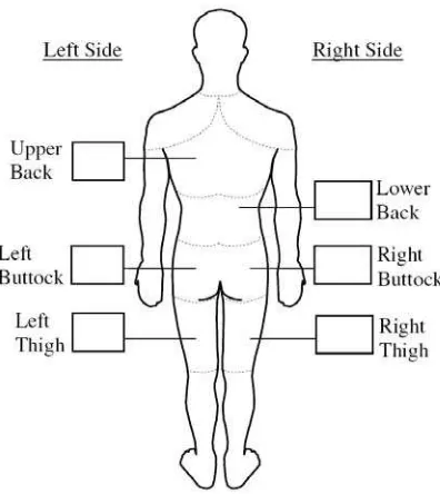
Body Mapping: In the body mapping method, the discomfort rating is focused to
a body part. The discomfort feeling scale is used to rate the body part. Kyung et al.
(2008) used a visual body mapping analogue scale as shown in Figure 2.6 to
obtain overall ratings of comfort and discomfort for different body parts. For the
work by Zenk et al. (2007), the body parts of seated participants were rated on