STUDY ON THE REVERSE ENGINEERING (RE) MEASUREMENT TECHNOLOGY
NORASFADZILA BINTI ABU HASSAN
STUDY ON THE REVERSE ENGINEERING (RE) MEASUREMENT TECHNOLOGY
NORASFADZILA ABU HASSAN
This report is submitted to the Faculty of Mechanical Engineering in partial fulfillment of requirements for the degree of
Bachelor Engineering Mechanical Engineering (Design & Innovation)
Faculty of Mechanical Engineering Universiti Teknikal Malaysia Melaka
ii
DECLARATION
“I hereby declare that the work in this report is my own except for summaries and quotations which have been duly acknowledged.”
Signature: ...
Author: Norasfadzila binti Abu Hassan
iii
Specially dedicated to:
My beloved father, Abu Hassan bin Lakim; mother, Zainah binti Kassim; siblings, lecturers and all my friends for their eternal support, encouragement and inspiration
iv
ACKNOWLEDGEMENT
Alhamdulillah, thank you to Allah S.W.T because of His blessing, I finally complete and finish my PSM successfully.
During the process to complete my project objective, I do a lot of research, either by using internet, reading past year thesis, reference books or journals. With the guidance and support from peoples around me, I finally complete the project due to the time given. Here, I want to give credit to those who helped me to achieve what I had achieved in my final year project.
First and foremost I would like to thanks to supervisor, Mr. Mohd Nazim bin Abdul Rahman for his guidance, critics, advices and motivation. He is a dedicated and diligent supervisor that would go all his way to help me with my problems.
Special thanks to Mr. Mohd Fadly bin Razikin, Mr. Mattew, and Mr. Baktiar bin Jarkasi from SIRIM Berhad, who kindly shared knowledge, guidance, support and assistance in my final year project.
I also want to thanks to my beloved parents because without them, I will not be able to do well in my final year project. They did give me a lot of support, both from money and moral support to help me continue for what I had started on.
v
ABSTRACT
vi
ABSTRAK
vii
viii
CHAPTER TITLE PAGES
2.2 Coordinate Measuring Machine (CMM) 8 2.2.1 Point of Origin and Measuring Range 11
2.2.2 Coordinates 12
2.2.3 Taking Measurements with the Coordinate
System 12
2.2.4 Software 13
2.3 Three-D Imaging Sensor 13
2.3.1 Overview of 3D Imaging Techniques 15
2.3.2 ATOS Digitizing 17
2.4.2 Tritop Coordinate Measurement System 26 2.4.3 Tritop System Configuration 28
2.3.10 Tritop Software 29
CHAPTER 3 METHODOLOGY 31
3.1 Methodology 31
3.1.1 Coordinate Measuring Machine (CMM) 34
ix
CHAPTER TITLE PAGES
CHAPTER 4 RESULT AND DISCUSSION 50
4.1 Result 50
4.1.1 CMM 51
4.1.2 ATOS 52
4.1.3 Tritop 54
4.1.4 Design Accuracy 55
4.1.5 Time Consumption 57
4.1.6 3-D View Colour Deviation
(CAD Comparison) 58
4.2 Discussion 60
CHAPTER 5 CONCLUSION AND RECOMMENDATION 62
5.1 Conclusion 62
5.2 Recommendation 63
REFERENCES 64
BIBLIOGRAPHY 67
x
2.6 ATOS scanning process (fringe pattern) 19
2.7 ATOS scanner 20
2.8 TRITOP measuring system: Photogrammetric camera with
Accessory 26
2.9 TRITOPCMM consumables: Self-adhesive and magnetic
markers 27
2.10 Display of bundle adjustment of three camera position 27
xi
NO. TITLE PAGES
3.10 Tritop results 49
4.1 Coordinate Measurement Machine measurement data 51
4.2 Graphics of element 52
4.3 ATOS scanning result 53
4.4 Calibrating images 54
4.5 Entities determination 55
4.6 Difference of measurement graph 57
xii
LIST OF TABLE
NO. TITLE PAGES
2.1 Classification of 3D imaging techniques 16
2.2 ATOS system configuration 21
2.3 TRITOP system configuration 28
3.1 List of the part 42
3.2 ATOS digitizing procedures 44
3.3 Material that used in ATOS scanner 46
4.1 Dimensional comparison 56
xiii
LIST OF APPENDIXES
NO. TITLE PAGES
A Measurement Setup 68
1
CHAPTER 1
INTRODUCTION
1.1 PROJECT BACKGROUND
2
1.2 PROBLEM STATEMENT
Much research work in the domain of coordinate metrology over the past few years has dealt with how to increase still further the accuracy of coordinate measurement by improvements in equipment and software. The emergence and development of non touch (3D scanner and photogrammetry) technology has recently opened the door to many new applications in the automotive and aeronautic industries. The latest ground-breaking innovation in the inspection and quality control world is the capability to replicate a series of measurements, traditionally obtained by various tools such as physical gages and CMMs, using a 3D digitizer and high-density point cloud inspection software.
3
1.3 PROJECT OBJECTIVES
The main objective of this project is to study the accuracy level in various reverse engineering technology. The accuracy and differences based on the touch method and non-touch method can be determined by using the Coordinate Measuring Machine, ATOS 3D digitizer and Tritop.
1.4 SCOPE OF PROJECT
The scope of this project will be the guidelines throughout this project to ensure the project is conducted within it‟s intend objectives. At the end of the project, it should be eventually achieved. The scopes are:
Literature study on the measuring machine (ATOS, Tritop and CMM). Analyze the accuracy and differences based on the touch method and
non-touch method.
4
CHAPTER 2
LITERATURE REVIEW
Conducting the literature review is done prior to undertaking the project. This will critically provide as much information as needed on the technologies available and methodologies used by other research counterparts around the world on the topic. This chapter provides the summary of the literature reviews on topics related to the reverse engineering measurement technologies.
2.1 AN OVERVIEW OF REVERSE ENGINEERING
The term "reverse engineering" includes any activity that determine how the product works, or to learn the ideas and technology that were originally used to develop the product. Reverse engineering is a way to redesign a product to reconstruct a new product which has similar functions and to improve the ability of the original product (Zainal Ab A. 1994). Reverse engineering can be use to study the design process, or as an initial step in the redesign process, in order to do any of the following:
• Observe and assess the mechanisms that make the device work • Dissect and study the inner workings of a mechanical device
5
Before deciding to do reverse engineering to a component, be sure to have sufficient information on the existing technical data of the component. For example, the process of reverse engineering can be use if the replacement parts of the component are required and the associated technical data is either lost, destroyed, non-existent, proprietary, or incomplete.
Reverse engineering initiates the redesign process, wherein a product is observed, disassembled, analyzed, tested, "experienced," and documented in terms of its functionality, form, physical principles, manufacturability, and ability to be assembled.
2.1.1 Applications Using Reverse Engineering
The intent of the reverse engineering process is to fully understand and represent the current instantiation of a product.
Here are just a few examples of how reverse engineering is making its presence felt in today‟s manufacturing environment. In the automotive world, Japanese manufacturers are using reverse engineering to shorten the process of developing a full-scale car design from three months to three days. Racing teams are using new digital processes to capture, recreate, and test engine and body parts that are critical to a car's on-track performance.
6
2.1.2 Measurement in Reverse Engineering
As computer-aided design (CAD) has become more popular, reverse engineering has become a viable method to create a 3D virtual model of an existing physical part for use in 3D CAD, CAM, CAE and other software. The reverse-engineering process involves measuring an object and then reconstructing it as a 3D model.
In general, measurement systems comprise of contact and non-contact methods (Cho, M. W. et al. 1995). The contact methods vary from simple measurement using tape to the sophisticated Coordinate Measuring Machine (CMM). These two methods are commonly used in mechanical engineering. Measurement using tape is conventional and subject to errors. The efficiency is low. Though CMM is totally automated and its measurement accuracy is 0.02mm, CMM requires a stable platform and the object‟s size is limited.
7
2.1.3 Why Use Reverse Engineering?
Even though reverse engineering services could appear to be a really fascinating thought, it canister be pretty challenging to work out how these services canister become useable for business outside of corporate espionage. Although it is surely legal that reverse engineering often canister be used by corporations to get an edge over each other in the R&D of new wares, this is definitely not the only usage it has: reverse engineering is pertinent to many designs ranging from redoing old technology to exploring the
b) The original manufacturer of a product no longer produces the product, e.g., the original product has become obsolete.
c) The original product design documentation has been lost or never existed.
d) Creating data to refurbish or manufacture a part for which there are no CAD data, or for which the data have become obsolete or lost.
e) Inspection and/or Quality Control–Comparing a fabricated part to its CAD description or to a standard item.
f) Some bad features of a product need to be eliminated e.g., excessive wear might indicate where a product should be improved.
g) Strengthening the good features of a product based on long-term usage. h) Analyzing the good and bad features of competitors‟ products.
i) Exploring new avenues to improve product performance and features.
j) Creating 3-D data from a model or sculpture for animation in games and movies. k) Creating 3-D data from an individual, model or sculpture to create, scale, or
reproduce artwork.
8
m) Fitting clothing or footwear to individuals and determining the anthropometry of a population.
n) Generating data to create dental or surgical prosthetics, tissue engineered body parts, or for surgical planning.
o) Documentation and reproduction of crime scenes.
2.2 COORDINATE MEASURING MACHINE (CMM)
A coordinate measuring machine is a device for measuring the physical geometrical characteristics of an object. This machine may be manually controlled by an operator or it may be computer controlled. It is often preferred above other length measuring tools because of its versatility, ease of use, and its uncertainty which is nevertheless a few micrometres only.
Generally CMM is designed to move a probe that measures and determines the coordinate of an object. CMM is not object dependent and can be widely used on any type of object. CMM can be fully automated and the output could easily be linked to a CAD system.
Typical precision of a coordinate measuring machine is measured in Microns, or Micrometres, which is 1/1,000,000 of a metre. A probe system, attached to the CMM, can be moved in a well known way in a certain measuring volume. It can be actuated either manually or by servo motors. Servo controlled axes give better reproducing probing, and therefore higher accuracy, and possibilities for automation. The probe, under computer control, touches a sequence of points in the surface of a physical object to be measured, and the CMM produces a stream of x, y, z coordinates of the contact points.
9
the probe might be broken when touching and retracting the difficult parts. The same attentions are also needed when using the displacement measuring probe; the possibility of breaking the probe is high while scanning the difficult surface. Mostly, the technician who is responsible for handling the CMM is an expert in the machine and the measuring probe only. Usually the technician must have little knowledge of the computer system and the computer software, which are attached to the CMM.
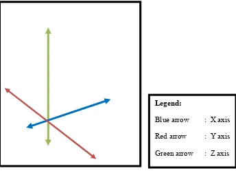
Figure 2.1: Coordinate in CMM
10
Figure 2.2: Main Component of CMM
Coordinate-measuring machines include three main components:
1) The main structure which include three axes of motion 2) Probing system
3) Data collection and Reduction system typically includes a machine controller, desktop computer and application software
The use of a CMM has been widely accepted for dimensional inspection of objects with complex surfaces. There exist several terms of automated inspection systems for complex surfaces using CMM. For example, (Ziemian, C. W., et al. 1997) refer to it as automated inspection planning; (Kim and Kim Kim, et al. 1996) refer to it as CAD-directed measuring strategy; (Ip, W. L.R. et al. 1996). refer to the system as the surface coordinate measurement method; (Skalski et al. 1998) call it the scanning measurement technique; (Hsieh et al.1993), just refer to it as reverse engineering that uses CMM; (Huang, X., et al. 1998) refer to it as CAD-model based inspection; (Yau,