antennas.
Index Terms—Array antennas, bismuth titanate, low-loss antenna, WiMAX.
I. INTRODUCTION
Ceramic antennas (CAs) have become attractive due to their partic-ular advantages for some applications, including zero conductor loss and low profile [1]–[8]. Various CA approaches have been described in the literature [1]–[12]. CAs with various shapes has been designed using a microstrip patch connected through a microstrip feeder [1]. An array of 323 CAs was designed with a size of 60 mm240 mm and that operated at 5.8 GHz. Results of 60-MHz bandwidth and 10-dB gain were reported [1]. Ref [3] presented a fractal rectangular CA for WiMAX application with a permittivity"0 = 20. The design dimen-sions were20 mm 2 12 mm 2 13 mm, and the ground plane size was 50 mm250 mm. The gain and directivity were 5.998 dB and 6.009 dB, respectively. Analysis of magnetic and electric properties on a 10-cm diameter disc with an antenna high miniaturization factor of 7–10 was reported in [4]. The need for miniaturization most probably is more im-portant for lower frequency bands at which the wavelengths are longer. However, this communication proved that high-frequency antenna de-signs also can achieve miniaturization but with a limited miniaturiza-tion factor due to the original small size.
Among all microwave transmission lines, the BiT ceramic feature offers extremely low losses up to a very high dielectric constant. For this reason, such devices have been utilized intensively as radiation patches and in the special feed system of planar arrays. Owing to these characteristics, the array elements will show high radiation efficiency, higher gain, and allow the production of miniaturized antennas.
In this study, we proposed a novel CA with a new branching struc-ture that uses ceramic material. This CA was designed with a rectan-gular cross-sectional area, termed as “rectanrectan-gular CA,” and was excited with a ceramic material that exhibited a permittivity value of 21. The study of the ReBiT array antenna was designed for a target resonant
Manuscript received December 28, 2011; revised March 23, 2012; accepted June 25, 2012. Date of publication August 03, 2012; date of current version November 29, 2012.
F. H. Wee and F. Ghani are with the School of Computer and Communica-tion Engineering, Universiti Malaysia Perlis, Perlis, Malaysia (e-mail: [email protected]; [email protected]).
F. Malek is with the School of Electrical Systems Engineering, Universiti Malaysia Perlis, Perlis, Malaysia (e-mail: [email protected]).
A. U. Al-Amani are with the School of Materials and Mineral Resources En-gineering (e-mail: [email protected]; [email protected]).
Color versions of one or more of the figures in this communication are avail-able online at http://ieeexplore.ieee.org.
Digital Object Identifier 10.1109/TAP.2012.2211557
Fig. 1. XRD pattern of the BiT powder at different calcination temperatures for 3 h: (a) 900 C, (b) 1000 C, and (c) 1100 C.
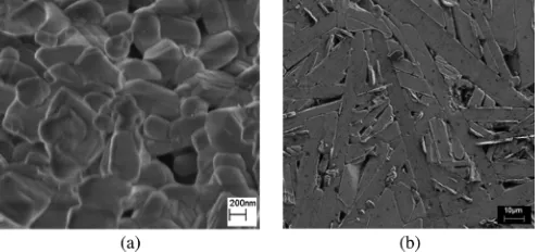
Fig. 2. FESEM image of BiT: (a) calcined powder at 750 Cfor 3 h and (b) sintered bulk ceramic at 1100 Cfor 3 h.
frequency at 2.30 GHz and to achieve an antenna return loss of less than010 dB to accommodate high radiation efficiency as well as the miniaturized antenna.
II. ANALYSIS OFBULKBISMUTHTITANATE(BIT) A. Sample Preparation
In this study, the raw materials used were bismuth pentahydrate and titanium (IV) isopropoxide. Both raw materials were dissolved sepa-rately into a mixture of 2-methaoxyethanol with acetylacetone, forming a Ti solution and a Bi solution. Both solutions were mixed and heated at 80Cto form a sticky gel and combusted to produce combusted powder. The calcination process was conducted at high temperature and pressure, i.e., 750Cand 100 MPa, respectively, to form a green body. Sintering was conducted at 1100Cfor densification purposes.
B. Characterization
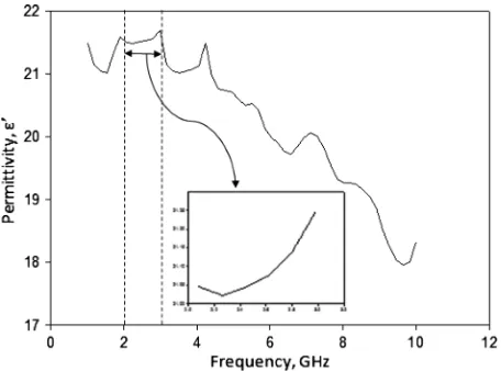
Fig. 3. Permittivity of BiT ceramic at 1 to 10 GHz.
TABLE I
PERMITTIVITY OFBIT ATFREQUENCIESFROM2TO3 GHz
We also investigated a new aspect of the development and utiliza-tion of the Agilent 85070B High Temperature Dielectric Probe Kit in measuring the permittivity of the BiT ceramic material. The frequency dependence of permittivity for BiT ceramic is shown in Fig. 3. As can be seen, the parameter has a strong dependence on frequency, with the permittivity decreasing as frequency increases; however, for the fre-quency range of 2 to 3 GHz, the average permittivity and loss tangent are 21 and 0.07 respectively, as shown in Table I. Tests of BiT exhib-ited low losses, with loss tangent values typically in the order of 0.05 with a tendency toward higher losses up to 0.08 at higher frequencies. The low-loss tangent values were obtained because BiT is free of con-ducting material, so it has no current flowing on its surface.
Measurement of the radiation pattern was performed in an anechoic chamber, as shown in Fig. 4. The anechoic chamber was used to max-imize the effectiveness and efficiency of the measurement space by reducing electromagnetic reflection and improving the quality of the measurements.
The antenna under test (AUT) was rotated through 360 degrees in the theta and phi axes so that E-field and H-field radiation patterns could be measured. The AUT was connected to the transmitting antenna stand in this measurement setup, and the receiving antenna was a circular po-larization antenna that allowed the signal from the AUT to be measured from all angles. To measure the gain of antennas, the received power PAUTof the AUT is measured. In this measurement, the receiving an-tennas must be matched to their loads (the receiver). The calculation of the gain of the AUT in dB uses the Friis transmission equation. The measurement leads to the following system of equations:
GAUT (dB)+ G0(dB)
= 20log10 4R + 10log10 PAUTP
o (1)
Fig. 4. Measurement of radiation patterns conducted in a microwave anechoic chamber.
GGS(dB)+ G0(dB)
= 20log10 4R + 10log10 PPGS
o (2)
whereGAUT (dB)is the gain of the AUT antenna;GGS(dB)is the gain of the gain standard; andG0(dB)is the gain of the transmitting antenna. From (1) and (2), we derived the expression for the gain of the test antenna as follows:
GAUT (dB)= GGS(dB)+ 10log10 PPAUT
GS (3)
If the AUT antenna is circularly or elliptically polarized, two orthog-onal, linearly-polarized gain standards must be used in order to obtain the partial gains corresponding to each linearly-polarized component. The total gain of the test antenna is
GAUT (dB)= 10log10(GAUT v+ GAUT h) (4)
whereGAUT is the dimensionless gain of the AUT antenna measured with the vertically-polarized gain standard, andGAUThis the dimen-sionless gain of the AUT antenna measured with the horizontally-po-larized gain standard.
To record the measurement data and radiation patterns, Passive Mea-surement software (PMS), integrated with the anechoic chamber, was used. Measurement data were collected at specific points in order to de-termine the radiation pattern. The PNA calculated the antenna gain, di-rectivity and efficiency as well as conducting 2-D and 3-D test. The test results for each angle and the displayed radiation pattern were plotted.
III. ANTENNACONFIGURATION ANDDESIGN
Fig. 6. Electric field of ceramic atHEM .
Fig. 7. (a) Electric field pattern (left) and magnetic field pattern (right) of
HEM . (b) Field propagation behavior when a port is placed parallel to the strongest field.
size of the patch is reduced to about0:20. To further reduce the size, array elements of BiT materials were introduced. Depending on the number of BiT elements added to the patch antenna, a size reduction of about 28% can be achieved. As an actual demonstration, a recently developed proposed antenna using an"0value of 21 and two-, four-and six-elements of BiT achieved a patch of25 2 22 2 1:6 mmat a frequency of 2.30 GHz (Fig. 9). Because the antenna is small structure from an electrical perspective, the antenna provided nearly complete spherical coverage as shown in the measured patterns in Fig. 10.
The proposed antennas have two layers, which are shown in Fig. 5. The first layer is a transmission line, which is shown in Fig. 5(a). Its optimal dimensions are presented in Fig. 7. The transmission line uses
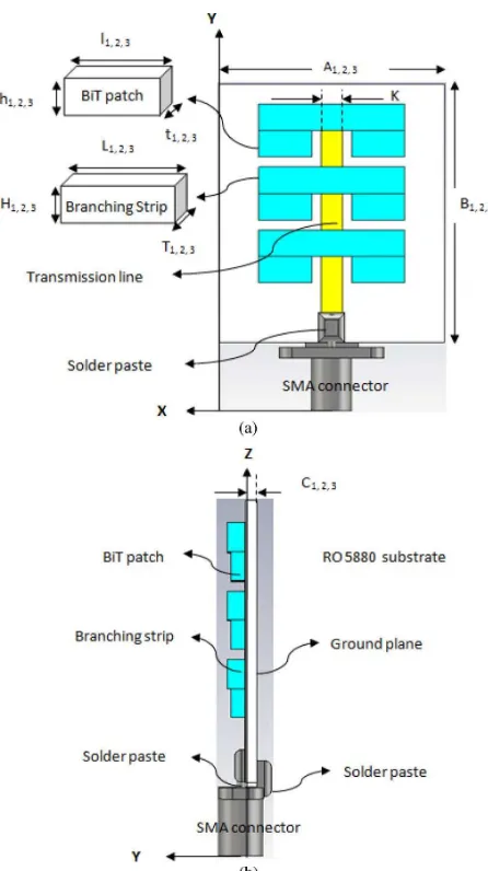
Fig. 8. Geometry layout of proposed ReBiT array antenna (a) front view (b) side view.
copper, which is a conducting material, in order to function as a feeding channel.
For the second layer of this investigation, the effectiveness of BiT was determined as power division and radiating element. The nov-elty of this design is the BiT ceramics that have high permittivity. The proper sizes, positions, and shapes were added to the second layer of the antenna, as shown in Fig. 5(b). The typical mode of operation in shielded environment isTE01, while in an open space, the typical mode isHEM11which the ceramic material acts as a radiator. Fig. 6 shows the electric field of the ceramic material in theHEM11mode.
The electric field is strong at the top and bottom surfaces of the ce-ramic, and this field propagation behavior indicates that a port can be placed parallel to the strongest field, i.e., along the y-axis of the res-onator, in order to couple to this mode effectively. This technique was utilized in the design of the ReBiT. In order to excite theHEM11mode, a port can be inserted close to the perimeter of the resonator, as shown in Fig. 7.
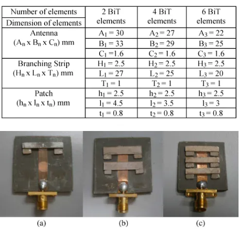
TABLE II
REBITSIZE FORTWO, FOUR,ANDSIXELEMENTS OFBIT
Fig. 9. Photograph of fabricated ReBiT array antennas (a) two-, (b) four-, and (c) six-BiT ceramic elements.
RT/Duroid 5880, commercial microwave substrate from Rogers Cor-poration (www.rogerscorp.com) with a permittivity of 2.20, where the BiT branching strips and patches exhibit permittivity of 21. The width of the transmission line was optimized atK = 4:6 mmin order to achieve input impedance matching of 50.
There are typically more losses associated with corporate feeds than series feeds due to radiation from the discontinuities and the longer lengths of the lines. Hence, this novel series linear array of ReBiT elements has the potential to reduce the high loss effect by utilizing non-conducting material that made of ceramic. This is due to the use of conventional conducting material will caused high loss thus, affect the antenna radiation performance.
From Table II, the size of the six-BiT element antenna can be ob-served as the smallest compared to both two- and four-BiT elements of ReBiT array antennas. In this case, the number of elements and the wavelength of the ceramic array antenna,g, can be approximated using:
g= pn"0
r (5)
wheregis the guided wavelength in CA,0is the free-space wave-length,"ris the dielectric constant of the ceramic, andndenotes the number of ceramic elements. Thus, a small size of ceramic is obtained with high-number of ceramic elements. This condition happens due to the present of the large area electromagnetic wave in the ceramic.
In addition to the modeling design, prototypes of the ReBiT array antennas with the optimized parameters were fabricated and measured, as shown in Fig. 9. This was done in order to ensure good agreement among their performances.
IV. RESULTS ANDDISCUSSION
Fig. 9 shows a graph of the return loss of the six elements of the ReBiT array antenna converted into log magnitude in dB.
Fig. 10. Simulated and measured return losses of the ReBiT array antennas.
Fig. 11. 2-D radiation pattern (a) E-plane (b) H-plane.
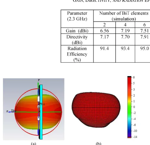
The simulation and measurement results show that the lowest return loss is027 dB with an operating bandwidth of 350 MHz. Overall, good agreement was found between the simulated and measured results, al-though there was a slight discrepancy between them that is believed to be due to the environmental effect and mechanical tolerance, which were neglected in our simulations. The gains and radiation efficiencies of the two-, four-, and six-BiT element ReBiT array antennas at 2.3 GHz are summarized in Table III.
The gain of the two-BiT element was 6.56 dB. This value increased up to a maximum of 7.51 dB for a six-BiT element, which was 1 dB higher than that of the two-BiT element. The reason for such a small change in the gain was that the surface area of the BiT was very small. Hence, interaction between the antenna and the BiT ceramic was mini-mized. However, the conventional dipole antenna also was simulated and its gain and directivity were measured for comparison with the BiT-array antenna. The conventional antenna achieved about 3.48 dBi and 4.83 dBi in gain and directivity respectively with 71.9% radiation efficiency as compared to 95% for BiT array antenna.
The simulated and measured radiation patterns in 2-D and 3-D views are shown in Figs. 11, 12, and 13 respectively. Both the E-field and H-field patterns incurred a slight change in shaped which in addition to errors in the manufacturing process were due to the imprecision of the dimensions of the BiT elements. The radiation pattern of the con-ventional dipole antenna exhibited omni-directional as BiT array an-tennas. For both BiT and conventional dipole antenna in Fig. 12 and 13 respectively, there were no top and bottom lobes at the rear end of the radiation pattern while the main directivity was directed at the vertical plane, which formed an omni-directional signal level in the H-plane.
Fig. 12. Radiation pattern of ReBiT in 3-D view (a) simulated (b) measured.
Fig. 13. Radiation pattern of conventional dipole antenna in 3-D view (a) sim-ulated (b) measured.
However, there is conduction loss occur only in the transmission line. Thus, the power output of the antenna is almost the same as the power input. The efficiency of the aperture is defined as:
n = AAeff
p (6)
whereis the aperture efficiency,Apis the physical size of the aper-ture, andAe is the effective aperture. The maximum equivalent area of an arbitrary antenna is related to its gain by:
Aeff = 2
4G (7)
whereApis the physical area of the BiT array antenna.
V. CONCLUSIONS
In this communication, the application of BiT in an array antenna was conducted successfully. The antenna exhibited acceptable band-widths, reflectivity, and radiation characteristics for WiMAX
applica-should be investigated in order to determine the improvement in per-formance that can be achieved in terms of bandwidth in particular and optimization of the radiation pattern in general.
REFERENCES
[1] M. F. Ain, Y. M. Qasaymeh, Z. A. Ahmad, M. A. Zakariya, M. A. Othman, A. A. Sulaiman, A. Othman, S. D. Hutagalung, and M. Z. Abdullah, “A novel 5.8-GHz array dielectric resonator antenna,”Progr. Electromagn. Res. C, vol. 15, pp. 201–210, 2010.
[2] M. F. Ain, S. I. S. Hassan, J. S. Mandeep, M. B. Othman, B. M. Nawang, S. Sreekantan, S. Hutagalung, and Z. A. Ahmad, “2.5-GHz dielectric resonator antenna,”Progr. Electromagn. Res., vol. PIER 76, pp. 201–210, 2007.
[3] R. K. Gangwar, S. P. Singh, and D. Kumar, “A modified fractal rect-angular curve dielectric resonator antenna for WiMAX application,”
Progr. Electromagn. Res. C, vol. 12, pp. 37–51, 2010.
[4] R. V. Petrov, A. S. Tatarenko, S. Pandey, G. Srinivasan, J. V. Mantese, and R. Azadegan, “Miniature antenna based on magnetoelectric com-posites,”Electron. Lett., vol. 44, no. 8, Apr. 10, 2008.
[5] J. Li, “An omnidirectional microstrip antenna for WiMAX applica-tions,”IEEE Antennas Wireless Propag. Lett., vol. 10, 2011. [6] S. Prabhu, J. S. Mandeep, and S. Jovanovic, “Microstrip bandpass filter
at S-band using capacitive coupled resonator,”Progr. Electromagn. Res., vol. PIER 76, pp. 223–228, 2007.
[7] R. K. Mongia, A. Ittipiboon, and M. Cuhaci, “Measurement of radia-tion efficiency of dielectric resonator antennas,”IEEE Microw. Guided Wave Lett., vol. 4, pp. 80–82, Mar. 1994.
[8] A. A. Kishk, X. Zhang, A. W. Glisson, and D. Kajfez, “Numerical analysis of stacked dielectric resonator antenna excited by a coaxial probe for wideband applications,”IEEE Trans. Antennas Propag., vol. 51, pp. 1996–2006, Aug. 2003.
[9] A. A. Kishk, “Wide-band truncated tetrahedron dielectric resonator an-tenna excited by coaxial probe,”IEEE Trans. Antennas Propag., vol. 51, pp. 2913–2917, Oct. 2003.
[10] M. T. Lee, K. M. Luk, K. W. Leung, and M. K. Leung, “Small dielec-tric resonator antenna,”IEEE Trans. Antennas Propag., vol. 50, pp. 1485–1487, Oct. 2002.
[11] S. Sreekantan, A. F. M. Noor, Z. A. Ahmad, R. Othman, and A. West, “Structural and electrical characteristics of crystalline barium titanate synthesized by low temperature aqueous method,”J. Mater. Process. Technol., vol. 195, no. 1–3, pp. 171–177, 2008.