Hindawi Publishing Corporation Advances in Acoustics and Vibration Volume 2009, Article ID 574604,3pages doi:10.1155/2009/574604
Review Article
Analytical Expression for Sound Transmission Loss Calculation:
An Improvement to the Existing Method after Singh and Katra
Iwan Yahya
The Iwany Acoustics & Applied Physics Research Group (iARG), Physics Department, Faculty of Mathematics and Natural Sciences, Sebelas Maret University, Jl. Ir. Sutami 36A Kentingan, Solo 57126, Indonesia
Correspondence should be addressed to Iwan Yahya,[email protected]
Received 12 September 2009; Accepted 23 October 2009 Recommended by Fidel E. Hernandez Montero
An analytical expression for measuring of sound transmission loss (TL) has been developed by using two microphones, an impedance tube and an impulse sound source as a proposed improvement to the existing procedure after Singh and Katra (1978). The calculation procedure is based on the autospectrum of short-time signals captured by the two microphones placed on two opposite positions from test sample while the sound source is on its surface. No spectral decomposition is required and the TL is calculated directly from the autospectrums of captured signals.
Copyright © 2009 Iwan Yahya. This is an open access article distributed under the Creative Commons Attribution License, which permits unrestricted use, distribution, and reproduction in any medium, provided the original work is properly cited.
1. Introduction
Understanding of acoustic parameter and/or properties of material is very important in many applications. Nowadays it is ranging from tissue analysis for medical purposes to elastic properties analysis of material such as attenuation and TL in engineering applications. Researchers have developed methods and measurement techniques for these purposes. Such measurements simply categorized into two main groups: first, the standing waves method by using impedance tube with single microphone and single tone sound source; this method is inefficient due to its time consuming [1,
2]; second, the spectral decomposition-based measurement, including a two-microphone impedance tube [3–5] and its four microphones improvement for TL measurement purposes [6–8]; the second group uses random noise instead of single tone sound source which is more efficient compared to the first group.
Another method for TL calculation is presented in this paper. The proposed method is an improvement to the previous one by Singh and Katra [9] and has been derived with two basic assumptions. (i) An impulse sound source is generated right on the sample surface while the two microphones are placed at two different opposite positions inside the tube. The microphone distance to the sample
surface should be longer compared to the tube diameter to ensure that the propagating wave is plane wave. (ii) Tube is sufficiently long, so there are no reflected waves from the both ends; for special purposes the utilization of anechoic termination is needed.
2. Existing TL Measurement Method by
Singh and Katra
In 1978, Singh and Katra introduced a procedure for mea-suring muffler characteristics based on impulse techniques as depicted inFigure 1.
2 Advances in Acoustics and Vibration
Sound source
Mic. number 1
Muffler
Mic. number 2
Figure1: Setup for measuring muffler characteristics developed by Singh and Katra.
Sound source Test sample
Mic.
number 1 number 2Mic.
x1 x=0 d x2
Figure2: Proposed setup configuration for the new TL
measure-ment.
The TL is then giving by
TL=10 log
S12
S22
S12
S22
∗
, (1)
where S12 is cross power spectrum of signals captured by the microphones andS22 is autopower spectrum of signal captured by microphone number two. The asterisk (∗) indicates complex conjugates ofS12andS22ratios.
3. Proposed Direct Calculation Procedure
It happens that reflected waves are also captured by micro-phone number one, so TL in (1) was not obtained directly from incident and transmitted waves power spectrum.
To do this direct calculation, the modified configuration is depicted inFigure 2.
Short-time impulse sound is radiated from a source located directly on the left surface of the test sample. Time window is set in same manner as in Singh and Katra’s method. Sound pressure values captured by the two microphones are given by
p1(x)=S11=p0eαx1,
p2(x)=S22=pde−α(x2−d), (2)
whereα = jk is the complex propagation constant of the waves in air inside the tube,
S11and
S22are autospectrum of the short-time captured signal by microphones number one and number two, respectively, and p0 and pd are the sound pressure levels of the signals atx=0 andx=d, and in this case theejωtterms were eliminated from the equations for simplification purpose.
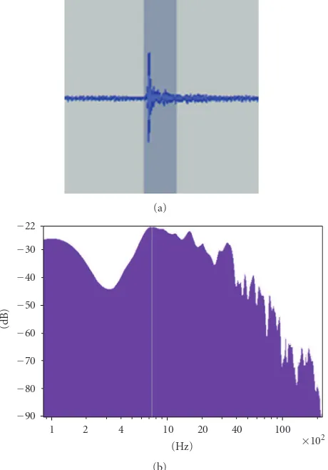
An illustration of the short-time captured signal and its spectrum is depicted inFigure 3. Both microphones capture the signal in a same size window. Autospectrum of these captured signals is then used for TL calculation purposes.
(a)
−90 −80 −70 −60 −50 −40 −30 −22
(dB)
1 2 4 10 20 40 100
(Hz) ×102
(b)
Figure3: Illustration of first arrival truncation process.
From (2), one could write the expression for the sound pressure level on both surfaces of the test sample, forx=0 andx=d, as follows:
p0(x)=S11e−αx1, (3)
pd(x)=
S22eα(x2−d). (4)
Letx2−d= −x1, then (4) becomes
pd(x)=S22e−αx1. (5)
Expression for the sound pressure level in the test sample is given by
ps(x)=p0e−αsx, 0≤x≤d, (6)
Advances in Acoustics and Vibration 3
TL is then calculated by comparing the intensity of the incident waves and transmission waves using the following relation: respectively,ρis the density of the air, andcis sound velocity. AiandAoare cross sections of both sides of the tube.
By using the relation in (3), then (8) changes to
Taking the boundary condition forx=dand using (5) and (6) givept=ps(d)=p0e−αsd=S22e−αx1. Equation (9)
could be rewritten as
Wt=S22e −2αx1
ρc Ao. (11)
Since both sides of the tube have an equal cross-section, Ai = Ao, substitution of (10) and (11) into (7) gives the expression for sound transmission loss as
TL=10 logS11 S22
. (12)
Substituting (3) and (5) into (6) forx=0 andx=d, we get the expression forαsas follows:
αs= −1
Since this method requires only calculation of autospec-trum of both truncated signals from the microphones, (12) and (13) show the effectiveness of the proposed method which is more simple in analysis compared to the previous calculation method by Singh and Katra, or even with the four-microphone technique.
Properly fitted anechoic termination is highly recom-mended to ensure that no parts of reflected waves are captured by the microphones. But this is not such a critical problem by the advance on surface microphone technology: by using a pair of surface microphones, a similar result could be obtained by placing the microphones properly on both surfaces of the test sample. An impulse sound source generated signal from the end of the tube or even the source placed on the sample surface, and TL could be derived directly from (6) with
The proposed method is more efficient and faster com-pared to the existing procedure, even promising a better performance by the advance of new surface microphone technology. The ability of giving similar result to previous techniques is the advantage of the current proposed method.
Acknowledgments
The author would like to thank his family for their support and patience, and also his colleagues and students at the Physics Department.
References
[1] P. Dickens, J. Smith, and J. Wolfe, “Improved precision in measurements of acoustic impedance spectra using resonance free calibration loads and controlled error distribution,”Journal of the Acoustical Society of America, vol. 121, no. 3, pp. 1471– 1481, 2007.
[2] S. Sugie, J. Yoshimura, and H. Ogawa, “Absorption characteris-tics of fibrous material covered with perforated facing and film,”
Acoustical Science & Technology, vol. 27, no. 2, pp. 87–96, 2006. [3] R. Lanoye, G. Vermeir, W. Lauriks, R. Kruse, and V. Mellert, “Measuring the free field acoustic impedance and absorption coefficient of sound absorbing materials with a combined particle velocity-pressure sensor,” Journal of the Acoustical Society of America, vol. 119, no. 5, pp. 2826–2831, 2006. [4] A. F. Seybert, “Two-sensor methods for the measurement of
sound intensity and acoustic properties in ducts,” Journal of the Acoustical Society of America, vol. 83, no. 6, pp. 2233–2239, 1988.
[5] “Standard test method for impedance and absorption of acoustical materials using a tube, two microphones, and a digital analysis system,” American Standard ASTM E 1050-98, 2003.
[6] Z. Tao and A. F. Seybert, “A review of current techniques for measuring muffler transmission loss,” inProceedings of the SAE Noise and Vibration Conference, 2003.
[7] A. R. Barnard and M. D. Rao, “Measurement of sound transmission loss using modified four microphones impedance tube,” inProceedings of the ASME Noise Control and Acoustics Division (Noise-Con ’04), Baltimore, Md, USA, July 2004. [8] O. Olivieri and J. S. Bolton, “Measurement of transmission