Observer based output feedback tuning for underwater remotely operated vehicle
based on linear quadratic performance
Mohd Shahrieel Mohd Aras, Shahrum Shah Abdullah, Muhammad Nizam Kamarudin, Ahmad Fadzli Nizam Abdul Rahman, Fadilah Abd Azis, and Hazriq Izzuan Jaafar
Citation: AIP Conference Proceedings 1660, 070051 (2015); doi: 10.1063/1.4915769 View online: http://dx.doi.org/10.1063/1.4915769
View Table of Contents: http://scitation.aip.org/content/aip/proceeding/aipcp/1660?ver=pdfcov Published by the AIP Publishing
Articles you may be interested in
Linear drift error for cornerstone autonomous underwater vehicle J. Acoust. Soc. Am. 130, 2527 (2011); 10.1121/1.3655088
Model Reduction by Balanced Truncation of Linear Systems with a Quadratic Output AIP Conf. Proc. 1281, 2033 (2010); 10.1063/1.3498345
Dynamic Output Feedback For Nonlinear Systems Using Linear Technique AIP Conf. Proc. 1107, 216 (2009); 10.1063/1.3106476
Exploiting autonomous underwater vehicle mobility for enhanced sonar performance J. Acoust. Soc. Am. 115, 2615 (2004); 10.1121/1.4784799
Connection between the existence of bisolitons for quadratic nonlinearities and a factorization of the associate linear operator
J. Math. Phys. 24, 2042 (1983); 10.1063/1.525945
Observer Based Output Feedback Tuning for Underwater
Remotely Operated Vehicle Based on Linear Quadratic
Performance
Mohd Shahrieel Mohd Aras
a, Shahrum Shah Abdullah
b, Muhammad
Nizam Kamarudin
c, Ahmad Fadzli Nizam Abdul Rahman
d,
Fadilah Abd Azis
aand Hazriq Izzuan Jaafar
ca
Department of Mechatronics, Faculty of Electrical Engineering, Universiti Teknikal Malaysia Melaka, Hang Tuah Jaya, 76100 Durian Tunggal, Melaka, Malaysia
b
Department of Electric and Electronics, Malaysia-Japan International Institute of Technology, Universiti Teknologi Malaysia, International Campus Jalan Semarak,
54100 Kuala Lumpur, Malaysia
c
Department of Control and Automation, Faculty of Electrical Engineering,
Universiti Teknikal Malaysia Melaka, Hang Tuah Jaya, 76100 Durian Tunggal, Melaka, Malaysia
d
Faculty of Information Technology and Computer Engineering,
Universiti Teknikal Malaysia Melaka, Hang Tuah Jaya, 76100 Durian Tunggal, Melaka, Malaysia
Abstract: This paper describes the effectiveness of observer-based output feedback for Unmanned Underwater Vehicle (UUV) with Linear Quadratic Regulation (LQR) performance. Tuning of observer parameters is crucial for tracking purpose. Prior to tuning facility, the ranges of observer and LQR parameters are obtained via system output cum error. The validation of this technique using unmanned underwater vehicles called Remotely Operated Vehicle (ROV) modelling helps to improve steady state performance of system response. The ROV modeling is focused for depth control using ROV 1 developed by the Underwater Technology Research Group (UTeRG). The results are showing that this technique improves steady state performances in term of overshoot and settling time of the system response.
Keywords: Observer-Based Output Feedback; linear quadratic regulation; unmanned underwater vehicle; remotely operated vehicle.
PACS:05.
INTRODUCTION
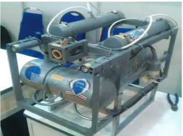
Remotely Operated underwater Vehicle (ROV) is one of unmanned underwater vehicle tether by umbilical cable at underwater platform by pilot. FIGURE 1 shows the platform of ROV developed by UTeRG team with integrated sensor to obtain the modeling using system identification technique called SMART ROV 1. Design and specification of the ROV can refer in [1][2][3][4][5].This SMART ROV 1 have four thrusters where two thrusters for depth motion whereas another two for forward or reverse motion with 45o tuning angle. The
experimental set up focuses on depth control. The experimental set up will be in a controlled water environment such as a lab tank and swimming pool. For depth control, overshoot in the system response are particularly dangerous [6]. Clearly an overshoot in the ROV vertical trajectory may cause damages to both the ROV and the inspected structure such as operates in cluttered environment [6][7]. Micro-Box 2000/2000C is a solution for prototyping, testing and developing real-time system using standard PC hardware for running real-time applications as shown in FIGURE 2. Microbox 2000/2000C acts as microcontroller and also called as XPC target machine. By using system identification toolbox in MATLAB, the modeling of ROV is obtained and being use to design the best controller for depth control. This paper also describes model obtained from strip theory.
This paper is organized as follows. In section 1, the introduction of Remotely Operated underwater Vehicle attached with the pressure sensor system is mentioned. Furthermore, Section 2 presents the theoretical on the mathematical modeling while Section 3 describes the literature review of other researchers. Last but not least,
Section 4 and Section 5 illustrate the field testing results and compared with other researcher’s simulation
FIGURE 1. SMART ROV 1 system.
FIGURE 2. MATLAB Simulink for System Identification of ROV design.
MATHEMATICAL MODELING
When analyzing the motion of ROV in 6 Degree of Freedom (DOF) it is convenient to identify two coordinate frames that is body-fixed frame and earth-fixed frame as demonstrated [8]. Body-fixed frame is the moving coordinate frame - fixed to the centre of gravity of the ROV. Underwater vehicles motion model can be derived from dynamics equation of underwater vehicle. The dynamics of a 6-degree-of-freedom underwater vehicle can be described in the following general form as formula (1) in [8][9]:
݉ݒሶ ܥሺݒሻݒ ܦሺݒሻݒ ݃ሺߟሻ ൌ ܤሺݒሻݑ
(1)
where,
m is the 6 x 6 inertia matrix including hydrodynamic added mass. C(v) is the Matrix of Coriolis and centripetal forces.
D(v) is the Hydrodynamic damping matrix.
g(η) is the Vector of restoring forces and moments.
B(v) is the 6 x 3 control matrix.
Generating mathematical model of unmanned underwater vehicle is very challenging because of the nature of underwater dynamics mainly due to the non-linear and coupled character of plant equations. The challenge is also due to the lack of precise model of underwater vehicles dynamics and parameters, as well as the appearance of environment disturbances [10]. It is possible to simplify the number of parameter making the certain
070051-2
assumption related with ROV’s construction. The following assertions were made for the dynamics of the ROV
in order to simplify the modelling:
o The ROV travels at low speeds, that is, less than 1m/s
o Roll and pitch movement is passively controlled and therefore, considered to be negligible o The ROV is considered to be symmetrical about its three planes
o During all manoeuvres the ROV is always maintained in a horizontal posture
o Disturbances from the water environment on the ROV such as currents and waves are negligible o Sway, that is, movement along the vehicle’s y axis, is negligible
o The ROV’s degrees of freedom are decoupled
Since the ROV is considered to be fairly symmetrical and travels at low speed, the decoupling for the
vehicle’s degrees of freedom is valid. The decoupling means that the Coriolis and centripetal terms matrices
become negligible and consequently can be eliminated from the dynamic model. The simplified dynamic model for the ROV then becomes,
݉ݒሶ ܦሺݒሻݒ ݃ሺߟሻ ൌ ܤሺݒሻݑ
(2)
This means that only the inertial and damping parameters need to be identified for the ROV. The above assertions not only have important ramifications for the modelling of the ROV, but also for its control.
SIMPLIFYING THE DYNAMIC MODEL MATRICES
Based on the assumptions presented in the previous section, as well as measurements performed on the vehicle, the matrices of the dynamic model from [11] were simplified and adapted to the ROV. These simplified matrices are presented in this section. Note that since sway, roll and pitch are negligible, then the corresponding parameters in the following matrices have been set to zero since they are not required to be identified for controlling the ROV [12].
Mass and Inertia Matrix
With the vehicle frame positioned at the centre of gravity and since the vehicle is assumed fairly symmetrical about all axes, then MRB can then be simplified to a good approximation to (3) [4].
»
»
»
»
»
»
»
»
¼
º
«
«
«
«
«
«
«
«
¬
ª
Z Y X RBI
I
I
m
m
m
M
0
0
0
0
0
0
0
0
0
0
0
0
0
0
0
0
0
0
0
0
0
0
0
0
0
0
0
0
0
0
(3)Since roll, pitch and sway are considered negligible, and then equation (3) can be further simplified to,
where the mass of the “SMART ROV 1” was measured to be 18kg. It can be seen from equations (4) that the
only parameter that needs identification for this matrix is the inertial moment about the z axis corresponding to yaw. Analogous to the simplification of MRB, the added mass matrix, MA, becomes,
»
»
»
»
»
»
»
»
¼
º
«
«
«
«
«
«
«
«
¬
ª
x x x r w u AN
Z
X
M
0
0
0
0
0
0
0
0
0
0
0
0
0
0
0
0
0
0
0
0
0
0
0
0
0
0
0
0
0
0
0
0
0
(5)Hydrodynamic Damping Matrix
The hydrodynamic damping matrix, D (V), simplifies to equation (6),
»
»
»
»
»
»
»
»
¼
º
«
«
«
«
«
«
«
«
¬
ª
|
|
0
0
0
0
0
0
0
0
0
0
0
0
0
0
0
0
0
0
0
0
|
|
0
0
0
0
0
0
0
0
0
0
0
0
0
|
|
)
(
| | | | | |r
N
N
w
Z
Z
u
X
X
v
D
r r r w w w u u u (6)Gravitational and Buoyancy Vector
The weight of the SMART ROV was found to be 176.4N while the buoyant force was measured as 196N. Keeping in mind that roll and pitch are negligible, significantly simplifies to equation (7),
» » » » » » » » ¼ º « « « « « « « « ¬ ª 0 0 0 0 0 rov b f f
G (7)
The value of -19.6N implies that the vehicle has residual buoyancy just as it was designed to have. The
residual buoyancy equates to 4% of the vehicle’s weight. Equation 6 shows that the gravitational and buoyant
forces of the vehicle only affect the heave of the vehicle. This is expected given that the centres of gravity and buoyancy are aligned along the x and y axes, and hence, the gravitational and buoyant forces should then only affect vertical movement.
Forces and Torque Vector
By measuring the positions of the motors on the “SMART ROV 1”, a layout of the thrusters depicting their respective distances to the vehicle’s centre of gravity was attained. This can be seen in equation 8. The mapping
matrix, L, for the SMART ROV 1 is given to a good approximation by,
070051-4
»
»
»
»
»
»
»
»
¼
º
«
«
«
«
«
«
«
«
¬
ª
5
5
2
2
4
4
1
1
3
3
0
0
1
1
0
0
0
0
0
0
0
0
1
1
L
L
L
L
L
L
L
L
L
L
L
(8)while the thrust vector is given by,
»
»
»
»
¼
º
«
«
«
«
¬
ª
4 3 2 1T
T
T
T
U
(9)where T1, T2, T3, T4 represent the thrusts of the portside, starboard, bow and stern motors respectively. In
equation 9, the first three rows signify whether or not a particular motor has an effect on the movement of the vehicle along the x, y and z directions. For instance, in the first row, the ones in the first two columns indicate that the horizontal motors are responsible for surge. The last three rows of the mapping matrix denote the distances from the centre of gravity to the thrusters. These values are either positive or negative corresponding to anticlockwise or clockwise moments respectively. The moments that are produced are responsible for
affecting the vehicle’s attitude. As can be seen in the fifth row of the mapping matrix, not only do the two
vertical motors contribute to pitch, but so do the two horizontal motors. This implies that when the vehicle is surging either forwards or backwards, the horizontal motors will affect the pitch of the vehicle. However, when performing underwater manoeuvres, this effect was not observed, implying that the contribution to pitch by the horizontal motors is not significant. This is most likely attributable to the passive pitch control system. Also observed in the fifth row is the fact that each vertical motor is equidistant from the centre of gravity. Consequently, applying equal forces to these motors when diving, surfacing or hovering will maintain the vehicle in a reasonably horizontal posture.
OBSERVER BASED OUTPUT FEEDBACK
BASED ON LQR PERFORMANCE
Notice that the value of A, B, C, and D matrices of our plant are known, so we can use these exact values in
estimator. The input to the system, the output of the system, and the system matrices of the system are known. What we do not know, necessarily, are the initial conditions of the plant. What the estimator tries to do is to make the estimated state vector approach the actual state vector quickly, and then mirror the actual state vector. We do this using the following system for an observer. A state observer is a system that models a real system in order to provide an estimate of its internal state, given measurements of the input and output of the real system. It is typically a computer-implemented mathematical model. FIGURE 3 shows the block diagram of observer based feedback control output based on LQR using MATLAB simulink.
FIGURE 3. System configuration for observer based output feedback tracking control.
FIGURE 4. Block diagram for Observer.
RESULTS AND ANALYSIS
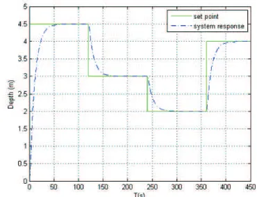
FIGURE 5 are shows the result observer based feedback output control based LQR. TABLE 1 and TABLE 2 are shows the performances of system response in term of steady state performances and execution time. The parameter of K, P, E will be tuning using MATLAB m-file as given in TABLE 3. FIGURE 6 shows closed up system response for observer based feedback output control based LQR. FIGURE 7 shows the estimate state. Our intention of this research to reduced error and increase steady state performances. The overshoot percentage of the system performances is below than 1.5%. So it considers being good performances and the SSE below than 1%.
TABLE (1). Steady state performances.
Item LQR
Peak time, Tp (s) 75
Rise time, Tr (s) 70
Settling time, Ts (s) 75
Overshoot percentage (%) 0.7 Steady state error, ess 0.2
070051-6
[image:7.612.136.475.577.664.2]TABLE (2). Execution Time
Type of Controller Computation Time
LQR 11.87 s
TABLE (3). Parameter of LQR
Parameter Value
K 0.7610 -0.6065 0.7841 1.0000 P 1.0319 -0.0906 1.4143 0.7553 -0.0906 0.1548 0.0538 -0.1868 1.4143 -0.0538 8.9791 0.6606 0.7553 -0.1868 0.6606 1.8561
E -2.5611 + 6.8916i
-2.5611 - 6.8916i -0.6031 + 0.2326i -0.6031 - 0.2326i
G 1.0e+003 *
[image:8.612.128.486.51.305.2]6.2821 -7.0501 0.1209 0.0595
[image:8.612.125.484.79.546.2] [image:8.612.120.490.332.615.2]FIGURE 6. Closed up system response.
FIGURE 7. Estimate state
070051-8
CONCLUSION
The parameter of observer based output feedback based on Linear Quadratic Regulation (LQR) performance for Unmanned Underwater Vehicle (UUV) are successfully done. This technique will be improved steady state performance of system response for depth controls using SMART ROV 1 develop by UTeRG research group. The parameter LQR will be tuning based on output of system and error to get the range of parameter. The comparison between conventional controller and Observer based output feedback-LQR gives better performances compared others. The future works can be done the value of M and N can be tuned using artificial intelligence technique such as Fuzzy Logic, neural network or particle swarm so that the parameter will be better.
ACKNOWLEDGMENTS
The authors gratefully acknowledge the continuous support from Universiti Teknikal Malaysia Melaka (UTeM) for UTeM Underwater Technology Research Group (UTeRG) through various grant provided to the research group. Special appreciation and gratitude to honourable University (UniversitiTeknikal Malaysia Melaka, UTeM and UniversitiTeknologi Malaysia, UTM) especially to the both Faculty of Electrical Engineering for providing the financial as well as moral support to complete this project successfully.
REFERENCES
1. Aras M. S. M., Azis F. A., Othman M. N. and Abdullah, S. S., “A Low Cost 4 DOF Remotely Operated Underwater
Vehicle Integrated With IMU and Pressure Sensor”, 4th International Conference on Underwater System Technology: Theory and Applications, 2012, pp 1-6.
2. Aras, M. S. M., Abdullah, S. S., Shafei, S.S., Rashid, M. Z. A. and Jamali, A., Majlesi Journal of Electrical Engineering6(2), 1- 12 (2012).
3. Aras, M. S. M., Kasdirin H. A., Jamaluddin M. H. and M. F. Basar, “Design and Development of the Multi Input
Sensor Algorithm for Autonomous Underwater Vehicle (AUV FKEUTeM)”, Malaysian Technical Universities Conference on Engineering and Technology, 2009, pp. 1-5.
4. Aras, M. S. M, S. S. Abdullah , Rashid, M. Z. A., Rahman, A. Ab. and Aziz, M. A. A., Journal of Theoretical and Applied Information Technology56, 1-7 (2013).
5. Azis F. A., Aras M. S. M., Abdullah, S. S., Rashid, M. Z. A. and Othman, M. N., Procedia Engineering41, 554-560
(2012).
6. Zhijie Tang, Luojun and Qingbo He, LSMS/ICSEE 2010 Part II,LNCS 6329, 218-224 (2010).
7. Aras, M. S. M., S. S. Abdullah, Rashid, M. Z. A., Rahman, A. Ab. and Aziz, M. A. A., Journal of Theoretical and
Applied Information Technology57, 1-10 (2013).
8. T.I. Fossen, Guidance and Control of Ocean Vehicles, New York: Wiley, 1994. 9. J. Yuh, IEEE Transactions on Systems, Man and Cybernetics20, 1475–1483 (2012).
10. Mohd Shahrieel Mohd Aras, Shahrum Shah Abdullah, Azhan Ab Rahman and Muhammad Azhar Abd Aziz,
International Journal of Advanced Robotic Systems10, 1 – 12 (2013).
11. Aras, M. S. M., S. S. Abdullah Rashid, M. Z. A., Rahman, A. Ab. and Aziz, M. A. A., Journal of Engineering and Applied Sciences8(6), 208-214 (2013).
12. Kashif Ishaque, S. S. Abdullah, S. M. Ayob and Z. Salam, Journal of Intelligent and Robotic Systems59(1), 87-100
(2010).