UNIVERSITI TEKNIKAL MALAYSIA MELAKA
VIDEO TRANSMISSION IMPLEMENTATION OF
OPTICAL FIBER CONCEPT IN COMMUNICATION
SYSTEM
This report submitted in accordance with requirement of the Universiti Teknikal Malaysia Melaka (UTeM) for the Bachelor Degree In Electronics Engineering Technology of
(Telecommunication) with Honours
by
MUHAMMAD HAFIZ BIN SULAIMAN B071110050
891014-14-5545
DECLARATION
I hereby, declared this report entitled “VIDEO TRANSMISSION IMPLEMENTATION OF OPTICAL FIBER CONCEPT IN
COMMUNICATION SYSTEM”
is the results of my own research except as cited in references.
Signature : ……….
Author’s Name : Muhammad Hafiz Bin Sulaiman
APPROVAL
This report is submitted to the Faculty of Engineering Technology of UTeM as a partial fulfillment of the requirements for the Bachelor Degree in Electronics Engineering Technology (Telecommunication) with Honours. The member of the supervisory is as follow:
ABSTRAK
Gentian optik merupakan revolusi teknologi masa kini. Dengan perkembangan teknologi yang pesat gentian optik merupakan teknologi yang terpantas untuk menghantar maklumat dari satu tempat ke suatu tempat yang lain. Teknologi yang menggunakan gentian optik ini mempunyai banyak kelebihan berbanding dengan kaedah perhubungan elektronik yang biasa dan ianya lebih selamat dan mesra alam. Didalam kajian projek ini lebih merujuk kepada analisis gentian optik. Analisis yang dilakukan adalah sumber optik, pemancar cahaya dan pengesan cahaya. Berikut merupakan kajian yang sangat penting untuk memastikan kelancaran,efisiensi dan kerja yang dilakukan oleh gentian optik untuk menghantar maklumat sempurna. Kajian komunikasi penghantaran video dengan menggunakan gentian optik dilakukan.
ABSTRACT
Optical Fiber technology is are revolutionizing world communications. The method of transmitting information from one place to another by sending pulse of light. The impact of fiber materials, devices and systems on communications in the coming decades will create an abundance of primary literature and the need for up to date reviews. These project is about to analyze optical source, detector and photo-receiver of the simple video transmission communication system using optical cable. The main part is the implementation of optical fiber in communication system. This video transmission communication system consist of a transmitter, which encode a message into an optical signal, a channel (Optical cable), which carries the signal and convert the signal into form that can be understood like and video. An optical-fiber guide consists of a small-diameter cylindrical core of silica or glass surrounded by a cladding of lower refractive index. The objective of the project is to improve the capability of fiber optic transmission by research base on the attenuation and losses.
DEDICATION
To my beloved parents
ACKNOWLEDGEMENT
Alhamdulillah, I have taken efforts in this project. However, it would not have been possible without the kind support and help of many individuals and
organizations. I would like to extend my sincere thanks to all of them.
I thank to my God (ALLAH) for providing me with everything that i required in completing this project.
I am highly indebted to the Supervisor in charge Mr Md Ashadi Bin Md Johari for his guidance and constant supervision as well as for providing necessary information
regarding the project & also for his support in completing the project.
I would like to express my gratitude towards my parents for their kind cooperation and encouragement which helped me in the completion of this project.
My thanks and appreciations also go to my classmates in developing the project and to the people who have willingly helped me out with their abilities.
TABLE OF CONTENT
2.1 BACKGROUND STUDY 4
2.2 LITERATURE REVIEW 6
2.2.1 OPTICAL COMMUNICATION 6
2.2.2 OPTICAL FIBER CABLES 7
2.2.3 OPTICAL FIBER MODES 7
2.2.3.1 SINGLE MODE STEP INDEX FIBER 7
2.2.3.2 MULTIMODE STEP INDEX FIBER 8
2.2.3.3 MULTIMODE GRADED INDEX FIBER 8
2.2.4 OPTICAL FIBER TRANSMISSION SYSTEM 8
2.2.4.1 OPTICAL TRANSMITTER OPTION AND DESIGN 9
2.2.4.2 OPTICAL FIBER MEDIUM 9
2.2.4.3 OPTICAL FIBER LOSSES 9
2.2.5 PROJECT ANALYSIS 13
CHAPTER 3 : METHODOLOGY 14
3.1 EXPERIMENT METHOD 14
3.2 FLOW CHART 16
3.3 SYSTEM ARCHITECHTURE 17
3.4 DATA COLLECTION 17
3.4.1 OPTICAL SOURCE 18
3.4.1.1 SEMICONDUCTOR LASER DIODE 19
3.4.1.2 LIGHT EMITTING DIODE 22
3.4.1.2.1 SEMICONDUCTOR LASER P-I CHARATERISITIC 25
3.4.1.2.2 LED P-I CHARACTERISTIC 26
3.4.2 PHOTODETECTOR 27
3.4.3 PHOTORECEIVER 32
CHAPTER 4 : RESULTS 35
4.1 SIMULATION RESULTS 37
4.1.1 OPTICAL SOURCE 37
4.1.1.1 OPTICAL SOURCE LASER CHARACTERISTIC
ANALYSIS 38
4.1.1.2 OPTICAL SOURCE LED CHARACTERISTIC
ANALYSIS 39
4.1.2 PHOTODETECTOR 40
4.1.2.1 SINGLE MODE OPTICAL FIBER 40
4.1.2.2 MULTI-MODE OPTICAL FIBER 42
CHAPTER 5 : CONCLUSION & FUTURE WORK 45
5.1 CONCLUSION 45
5.2 FUTURE WORK 47
CHAPTER 6 : REFERENCE 48
APPENDICES 50
LIST OF TABLE
Chapter 2 : Literature Review 4
2.1: Three stages fiber optic analysis 13
Chapter 3 : Methodology 14
3.1: Specification of Transmitter 24
3.2: Difference index of 1310nm 29
3.3: Specification Of Receiver 31
Chapter 4: Results 35
4.1: Comparison between electronic and optical source 37
4.2: Laser P-I characteristic V(mV) vs I(mA) 38
4.3: LED P-I characteristic V(mV) vs I(mA) 39
LIST OF FIGURE
Chapter 2: Literature Review 4
2.1: The Electromagnetic Spectrum 5
2.2: Schematic of a conventional silica fiber structure 7
2.3: The light is scattered in all directions 12
Chapter 3 : Methodology 14
3.1: Flow chart 16
3.2: Fiber optic communication system 17
3.3: The Basic Fiber Optic Transmission System 18
3.4: Semiconductor laser P-I curve 20
3.5: Operation of laser 21
3.6: LED P-I curve 23
3.7: A Simple Transmitter Diagram 24
3.8: Advanced Fiber optic Communication Trainer with
SDH (Central Controller) 24
3.9: Advanced Fiber optic Communication Trainer with
SDH (Light transmitting) 27
3.10: Schematic of current voltage conversion 30
3.11: Schematic of detector current flow 30
3.12: A Simple Receiver Diagram 31
3.13: Fiber optic Communication Trainer with SDH (Light receiving) 32
3.14: Block diagram of digital photoreceiver 32
3.15: Schematic diagram of optical receiver 34
Chapter 4 : Results 35
4.1: Video transmission implementation of optical fiber in
communication system 37
4.2: Graph of semiconductor laser P-I characteristic
power (uW) vs current (mA) 38
4.3: Graph of LED power (nW) vs current (mA) 40
4.4: Oscilloscope calibration 40
4.5: Single mode optical fiber 1310nm fiber cable type analysis 41
4.6: Single mode optical fiber 1310nm fiber cable type analysis 42
4.7: Oscilloscope calibration 42
4.8: Multimode optical 850nm fiber cable type 43
4.9: Multimode optical 850nm fiber cable type 44
LIST OF ABBREVIATIONS
SDH - Synchronous digital hierarchy
CHAPTER 1
INTRODUCTION
1.1 PROJECT BACKGROUND
Optical Fiber technology is are revolutionizing world communications. The method of transmitting information from one place to another by sending pulse of light. The impact of fiber materials,devices and systems on communications in the coming decades will create an abundance of primary literature and the need for up to date reviews.
The first ultrapure fiber was fabricated in 1970. This breakthrough led to a series of technology developments related to optical fibers according to (Keiser, 2015, p. xxii). Initially the technology focused on a simple transmission links but quickly moved to increasingly sophisticated networks. Modern high capacity telecommunication networks based on optical fiber technology now have become an integral and indispensable part of society. Due to the importance of these network to everyday life, users have come to expect the communication service to always be available and to function properly (Keiser, 2015, p. 1).
The project is about to analysis the simple video transmission communication system using optical cable. The main part is the implementation of optical fiber in communication system. This video transmission communication system consist of a transmitter, which encode a message into an optical signal , a channel (Optical cable), which carries the signal and convert the signal into form that can be understood like and video. An optical-fiber guide consist of a small-diameter cylindrical core of silica or glass surrounded by a cladding of lower refractive index (MIDWINTER, 1980).
1.2 OBJECTIVE
The objective of this project is to analyze the video transmission implementation of optical fiber concept in communication system. The exploration in the application of an optical fiber is very important for the future. Plus to measure the attenuation of transmitter and receiver in optical fiber communication system. Since The technology the fiber is widely is use and become one of the important technologies in new era. Fiber optic is one of ways to upgrade the communication system.
1.3 PROBLEM STATEMENT
Nowadays,
a) The video images never be perfectly noise free.
b) Delay and noise of video transmission and audible acoustic noise. c) High attenuation and loss of optical cable transmission.
1.4 SCOPE OF WORK
The working scope of this project is to analyze video transmission implementation of optical fiber concept in telecommunication system. The scope are listed to ensure the project is conducted within its intended boundary. To ensure the project is heading in the right direction to achieve its objective. Scope of this project to study the Optical Fiber,Structure, Single-mode index fiber, Multimode step-index fiber, Optical Source and Photodetector.
The main focus for this project can be classified as:-
a) The basic of Optical Fiber Communication system. b) The attenuation of video transmission in optical fiber. c) The system of optical fiber communication operation.
The working scope of this project is to design analyze the attenuation two – ways video transmission implementation of optical fiber in communication system.
CHAPTER 2
LITERATURE REVIEW
2.1 BACKGROUND STUDY
Electromagnetic waves can be propagated in a waveguide consisting of a dielectric bounded by another dielectric of lower permittivity instead of by a conductor in general of optical fiber transmission (P.Cochrane, 1991, pp. 82,83). The use of such a waveguide,propagating waves of optical wavelengths, for communication transmission was proposed by Kao and Hockham (P.Cochrane, 1991, pp. 82,83) in 1966.
The practicability of such system depends on the availability of materials for the guide having sufficiently low energy losses, and suitable optoelectric devices for launching light waves into the guide and detecting them after transmission (P.Cochrane, 1991, pp. 82,83). A large research and development effort over the last twenty years has resulted in optical fiber with sufficiently low attenuation (Typically < 0.5 dB/km) and suitable solid state transmitting devices (Light-emitting diodes(LEDs) and lasers) and receiving device (P.Cochrane, 1991, pp. 82,83).
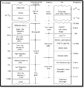
Figure 2.1: The Electromagnetic Spectrum
In these developments the basic trend for advancing the link capacity was to use increasingly higher channel frequencies (Forouzan, 2013). The reason for this trend is that a time-varying baseband information-bearing signal may be transferred over a communication channel by superimposing it onto a sinusoidal electromagnetic wave, which is known as the carrier wave or simply carrier (Crilly, 2010). At the destination the baseband information signal is removed from the carrier wave and processed as desired. Since the amount of information that can be transmitted is directly related to the frequency range over which the carrier operates, increasing the carrier frequency theoretically increase the available transmission bandwidth and, consequently, provide a larger information capacity (II, 2012).
Figure 2.1 shows the electromagnetic spectral bands used for radio transmission. As the diverse radio technologies move from high frequency (HF) to very high frequency (VHF) to ultra high frequency (UHF) bands with nominal
carrier frequencies of 107 , 108, and 109 Hz, respectively, increasingly higher information transmission speeds can be employed to provide a higher link capacity. Thus the trend in electrical communication system developments was to use progressively higher frequencies, which offer corresponding increase in bandwidth or information capacity (Keiser, 2015).
2.2 LITERATURE REVIEW
2.2.1 Optical communication
The implementation of optical fiber technologies are employed in a wide variety of communication environments such as telecommunications, networking, data communications, industrial communication links, medical communications links, etc. Fiber optic networks are in demand with the commonplace in telecommunications applications due to their increased bandwidth and distance capabilities relative to copper networks.
Optical fiber is the common technology nowadays. The typical optical communication system, and the low loss, light weight, small size, flexibility and high intrinsic bandwidth of optical fiber help make optical communication systems more desirable than competing systems for the communication of both of digital and analog signals
Fiber optic transmission devices, also called optical-electronic devices or optoelectronic devices, are coupled with optical fibers for data and signal transmission by converting optical signals into electrical signals, electrical signals into optical signals, or both. Fiber optic communication utilizes optical transmitters, optical receivers and optical fiber, among other components, to transmit light signals through the fiber.
2.2.2 Optical fiber cables
Optical fiber guide consists of small-diameter cylindrical core of silica or glass surrounded by a cladding of lower refractive index (SENIOR, 1985) . It confines electromagnetic energy in the form of light to within its surface and guides the light in a direction parallel to its axis. The transmission properties of an optical waveguide are dictated by its structural characteristics, which have a major effect in determining how an optical signal is effected as it propagates along the fiber (Keiser, 2015, p. 40).
Figure 2.2: Schematic of a conventional silica fiber structure (Matthew, 2012).
2.2.3 OPTICAL FIBER MODES
2.2.3.1 Single-mode step-index fiber
a) The refractive index of the core is uniform throughout and undergoes an abrupt change (or step) at the cladding boundary.
b) To reduce modal dispersion is to reduce the core’s diameter until the fiber propagates only one mode efficiently.
c) Has a very small core diameter of only 5-12 microns. The standard cladding diameter is 125 microns.
d) Modal dispersion does not exist.
e) Potential bandwidth of 50–100 GHz-kilometers (JACHETTA, 2007).
2.2.3.2 Multimode step-index fiber
a) The multimode step index fiber is the simplest type.
b) It has a core diameter from 100-970 microns and the fiber included with type of glass,PCS, and plastic fiber (JACHETTA, 2007).
c) Despite relatively low bandwidth and high losses.
d) The core refraction index is made to vary as a function of the radial distance from the center of the fiber.
2.2.3.3 Multimode graded-index fiber
a) Has a refractive index that decreases with increasing radial distance from theoptical axis of the fiber.
b) The core has numerous concentric layers of glass, somewhat like the annualar rings of a tree.
c) Each successive layer outward from the central axis has a lowe index of refraction.
d) Popular graded index fibers have a core diameter of 50 or 62.5 microns and cladding diameter of 125 microns (JACHETTA, 2007).
2.2.4 OPTICAL FIBER TRANSMISSION SYSTEMS
The early optical fiber had a attenuation is >1000 dB/km, but by the 1970 this had been reduced below 20dB enabling the first system demonstrations by Bell Labs (at 45 Mbit/s) and British Telecom (at 140 Mbits/s) on installed cables (P.Cochrane, 1991, p. 295). This successful led to the first production systems which operated at a wavelength of 850 nm over multimode fiber (P.Cochrane, 1991, p. 295). The singlemode fiber have been installed throughtout most modern telecommunication network and is now being considered for application in the local loop to serve domestic subscribers.
2.2.4.1 OPTICAL TRANSMITTER OPTION AND DESIGN
Semiconductor diodes are generally the only source used in optical communication system because of their small size,ease of modulation, relatively high electron-to-photon conversion effieciencies and realibility (WILSON & HAWKES, 1983) .There are only two broad categories of device: laser diode (LD), and light-emitting diode (LED) but within these categories are hundredsof different variants in term of their structure,material and operating materials.
2.2.4.2 OPTICAL FIBER MEDIUM
There have a different types of optical guiding media, ranging from commonly available plastic and silica glass to the more exotic research based materials such as fluoride. The same basic system design criteria are interest for whichever type of guide is selected. This include attenuation per unit length (dB/km). Microbending loss, dispersion, bandwidth, coupling efficiency, splice and connector loss, splice strength, available connector and installation stress (P.Cochrane, 1991).
2.2.4.3 OPTICAL FIBER LOSSES
a) Attenuation
The important consideration in the design of optical communication system is the attenuation of a light signal as it propagates along a fiber. The degree of attenuation plays a major role in determining the maximum transmission distance between a transmitter and a receiver or an a line amplifier. The basic attenuation mechanisms in a fiber are absorption, scattering and radiative losses of the optical energy (BUCK, 2004).
b) Attenuation unit
As light travels along a fiber, its power decrease exponentially with distance.
∝p=�1 ln ��(0) �(�)�
c) Fiber attenuation coefficient unit.
For simplicity in calculating optical signal attenuation in a fiber, the common procedure is to express the attenuation coefficient in units of decibels per kilometre, denoted by dB/km.
∝ ������ =10
� log� �(0)
�(�)�= 4.343 ∝ �(��−1)
This parameter generally referred to as the fiber loss or the fiber attenuation (Keiser, 2015, p. 95).
d) Absorption
Three different mechanism.
• Absorption by atomic defect in the glass composition
• Extrincsic absorption by impurity atoms in the glass material. • Intrinsic absorption by the basic constituent atoms of fiber material
(GAMBLING, 2000).
Limit on absorption for any particular material. It results from electronic absorption bands in the ultraviolet region and from atomic vibration bands in the near-infrared region. Absorption can occur when a photon interacts with an electron in the valence band and excites it to a higher energy level.