DESIGN AND ANALYSIS OF QUALITY ENHANCEMENT BY USING ERBIUM DOPED FIBER AMPLIFIER (EDFA) IN OPTICAL
COMMUNICATION LINK
NUR KHALIDA BINTI RAMLI
A thesis submitted in fulfillment of the requirements for the degree of Bachelor of Electronic Engineering (Wireless Communication) With Honours
Faculty of Electronic and Computer Engineering
UNIVERSITI TEKNIKAL MALAYSIA MELAKA
i
DECLARATION
“I hereby declare that this report is result of my own effort except for works that have been cited clearly in the references.”
ii
“I hereby declare that I have read this report and in my opinion this report is sufficient in terms of scope and quality for the award of Bachelor of Electronic
Engineering (Wireless Communication) with Honours”
Signature : ……….
iii
DEDICATION
iv
ABSTRACT
v
ABSTRAK
vi
ACKNOWLEDGEMENT
In the name of Allah, the Most Gracious and the Most Merciful
Alhamdulillah, all praises to Allah for the strengths and His blessing in completing this thesis. First and foremost, I must acknowledge and thank The Almighty Allah for blessing, protecting and guiding me throughout this period. I could never have accomplished this without the faith I have in the Almighty.
I have to thank my research supervisor, Mr. Chairulsyah Wasli and my co-supervisor, Dr. Yosza Dasril. Without their assistance and dedicated involvement in every step throughout the process, this paper would have never been accomplished. I would like to thank to both of you very much for your support and understanding over these past two semesters.
vii
TABLE OF CONTENTS
CHAPTER TITLE PAGE
DECLARATION i
DEDICATION iii
ABSTRACT iv
ABSTRAK v
ACKNOWLEDGEMENTS vi
TABLE OF CONTENTS vii
LIST OF TABLES x
LIST OF FIGURES xi
LIST OF APPENDICES xiii
LIST OF ABBREVIATIONS xiv
1. INTRODUCTION 1
OBJECTIVES 2
SCOPE OF WORK 3
PROBLEM STATEMENTS 4
PROJECT METHODOLOGY 4
ORGANIZATION OF THESIS 6
2. LITERATURE REVIEW 7
viii
OPTICAL COMMUNICATION 8
2.1.1 Fiber Cable 8
2.1.2 ITU Wavelength Grid 10
2.1.3 Optical Communication Band 11 WAVELENGTH DIVISION MULTIPLEXING (WDM) 12
2.1.4 Operation 13
ERBIUM DOPED FIBER AMPLIFIER (EDFA) 14
2.1.5 Structure of EDFA 14
2.1.6 Energy Level 15
2.1.7 Pump Source 16
2.1.8 Gain 17
2.1.9 Gain Flattening 19
2.1.10 Noise Figure 20
2.1.11 Application of EDFA 22
3. METHODOLOGY 23
FLOW OF PROJECT 23
TYPICAL SPECIFICATION OF EDFA 25
SIMULATION 26
3.1.1 Optiwave System Software 26
4. RESULTS AND DISCUSSIONS 28
CONSTRUCTION OF DESIGNED EDFA 28
PARAMETER OF THE EDFA DESIGN 30
RESULTS OF CALCULATION 32
RESULT OF SIMULATION 33
ix
5. CONCLUSION AND FUTURE WORK 40
REFERENCES 42
x
LIST OF TABLES
TABLES TITLE PAGE
2.1 ITU Wavelength Grid 11
2.2 WDM Band 12
3.1 Typical Specifications of EDFA 25
xi
LIST OF FIGURES
FIGURES TITLE PAGE
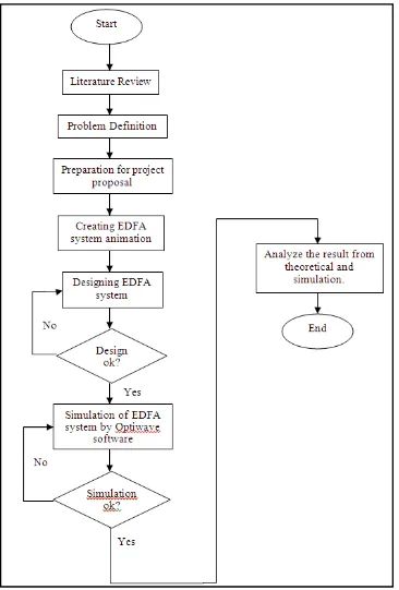
1.1 Flow Chart of Project 5
2.1 Basic Structure of Fiber Optic Cables 9
2.2 WDM Transmission Network 13
2.3 EDFA Structure 15
2.4 Energy Levels of EDFA 16
2.5 Types of EDFA Applications 22
3.1 Flow Chart of Project 24
3.2 Optiwave Software 27
4.1 The EDFA System Designed In The Optisystem Software
30
4.2 Graph of Gain (dB) and Noise Figure (dB) vs. Channel wavelength at various pump power
32
4.3 Graph of Gain (dB) and Noise Figure (dB) vs. Channel wavelength at various pump power
34
4.4 Graph of Output Power vs. EDF length over various pump power
xii 4.5 Graph Gain vs. Erbium ions density at different
pump power
37
4.6 Graph of Noise Figure vs. Erbium Ions Density over Different Pump Power
38
xiii
LIST OF APPENDICES
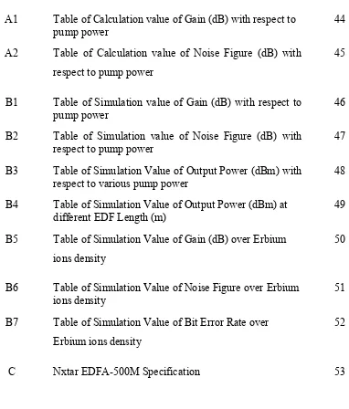
APPENDIX TITLE PAGE
A1 Table of Calculation value of Gain (dB) with respect to
pump power 44
A2 Table of Calculation value of Noise Figure (dB) with respect to pump power
45
B1 Table of Simulation value of Gain (dB) with respect to
pump power 46
B2 Table of Simulation value of Noise Figure (dB) with
respect to pump power 47
B3 Table of Simulation Value of Output Power (dBm) with
respect to various pump power 48 B4 Table of Simulation Value of Output Power (dBm) at
different EDF Length (m) 49
B5 Table of Simulation Value of Gain (dB) over Erbium ions density
50
B6 Table of Simulation Value of Noise Figure over Erbium
ions density 51
B7 Table of Simulation Value of Bit Error Rate over Erbium ions density
52
[image:14.595.122.504.282.730.2]xiv
LIST OF ABBREVIATIONS
WDM - Wavelength Division Multiplexing EDF - Erbium Doped Fiber
EDFA - Erbium Doped Fiber Amplifier
PSM - Projek Sarjana Muda nm - nanometer
mm - millimeter dB - decibels km - kilometer
Mbps - Mega bit per second
ITU - International Telecommunication Union ICT - Information and Communication Technology S - Short Wavelength
C - Conventional
L - Long
O - Original
xv
E - Extended
FDM - Frequency Division Multiplexing TDM - Time Division Multiplexing IR - Infrared
Tx - Transmitter Rx - Receiver
ASE - Amplified Spontaneous Emission Er+3 - Erbium
TFBG - Titled fiber Bragg gratings
SNR - Signal to Noise Ratio NF - Noise Figure
DFB - Distributed Feedback BER - Bit Error Rate
OSNR - Optical Signal to Noise Ratio µm - micrometer
mW - milliwatt
dBm - decibels-milliwatt
m - meter
G - Gain
xvi ∆v - Bandwidth
V - Frequency of signal
λp - Wavelength of pump source λs - Wavelength of signal Pp,in - Input pump power Ps,in - Input signal power Ps,out - Output signal power
CHAPTER 1
INTRODUCTION
Nowadays, fiber optic communication is well known in the telecommunication technologies and widely used to transport data from one point to any other point via fiber optic cable connections in the form of light. The composition of tiny glass fiber in that transmit light wave 10 000 greater than the highest radio frequencies in the fiber optic ensure a greater capacity of data and information than can be transported when compared with the standard cables. Capability to transport signals over long distances, minimum error rates, resistance to electrical interruption, security and light weight are the further benefits of using fiber optic over copper cables [1].
2 Erbium Doped Fiber Amplifier (EDFA) is a method of straight away boosting optical signals without the requirement to first transform it into an electrical signal before boosting after that convert back to optical signal after the amplification. Erbium doped fibers (EDF) are optical fibers doped with rare-earth element that features the proper energy in their atomic compositions for enlarging light. Basically, the in line boosting which simply no coupling loss present has capability with reduce interference, and thus fewer crosstalk rather than semiconductor optical amplifiers. The gain of EDFA may possibly achieve to 30dB and also employ 980nm pump wavelength.
1.1 OBJECTIVES
The objectives for this project are:
1. To study the Erbium Doped Fiber Amplifier (EDFA) from a theoretical aspect of all parameter resulted.
2. To design and analyze the usage of high quality Erbium Doped Fiber Amplifier (EDFA) in optical communication link for theoretical analysis and simulation. 3. To compare the qualitative by the performance of optical communication link
3
1.2 SCOPE OF WORK
The scope of work is divided into two parts which are PSM1 and PSM 2;
1.2.1. Projek Sarjana Muda I (PSM I) The tasks done for PSM 1 are as follow:
1. Creating animation that describes the overall operation of the Erbium Doped Fiber Amplifier (EDFA) in fiber optic communication link. This animation gives full understanding on how the signal transmitted in fiber optic is amplified through the EDFA.
2. Design Erbium Doped Fiber Amplifier (EDFA) system by using calculation. 3. Analyze the fiber optic communication link without using Erbium Doped Fiber
Amplifier (EDFA) through theoretical calculation. 4. PSM I report writng.
1.2.2. Projek Sarjana Muda II (PSM II)
For PSM 2, the task that has been done are shown below:
1. Simulate and measure the design Erbium Doped Fiber Amplifier (EDFA) system by using Optiwave software.
2. Testing and measurement of Erbium Doped Fiber Amplifier (EDFA) system at any company or university laboratory that have fiber optic communication and EDFA equipments.
4
1.3 PROBLEM STATEMENTS
In fiber optic communication, the transmitted signal in fiber optic communication may loss during transmission and the receiver may not able to receive the signal. Since to that problem, the use of amplifier is introduced to boost the attenuated signal so that the signal can reach the receiver. However, the electrical amplifier that commonly used to re-amplify the signal need optical to electrical signal converter which may cause problem to fiber optic communication system. Due to that problem, the necessity of optical amplifier that can enhance the quality of optical communication link has been considered.
1.4 PROJECT METHODOLOGY
5
6 1.5 ORGANIZATION OF THESIS
In the Chapter 1, this report discuss on the introduction of the project where the problem statement for this project is defined, the objectives are stated and the scope of work is explained and the flow chart of process for this project is shown.
In Chapter 2, the overall theory and the past research about this project is explained. The block diagram of the fiber optic communication system and the EDFA is shown and explained. The overall system operation is stated and the characteristic of the each component in the system is described.
In Chapter 3, the methodology of the project is discussed. There are two part of project methodology which is theoretical analysis and simulation. In calculation, the proposed designed is discussed and the parameter is described. The simulation part, the Optiwave software is explained.
In Chapter 4, the construction of the EDFA system is described and the parameter of the EDFA system that has been chosen is explained result of simulation is recorded and analyzed. The readings and chart from the simulation is recorded and described.
CHAPTER 2
LITERATURE REVIEW
2.1 BACKGROUND STUDY
A fundamental optical transmission link comes with transmitter and also receiver, with an optical fiber cable linking up both of them. Even though signals propagating in optical fiber experience way less attenuation compared with many other mediums, like copper, there may be still a constraint of roughly 100km on the range the signal are able to transmit before turning out to be too noisy to be detected [1]. Before the optical amplifier is developed, it was actually important to electronically reproduce the optical signals each 80-100km with a purpose to accomplish transmission over extensive distances. This resulted in accepting the optical signal, cleaning up as well as amplifying it electronically, after that retransmits it over the next section of the communication link.