Design and Construction of Liquid Level
Measurement System
K. A. Mohd Annuar*,a, N. A. Ab Hadib, I. M. Saadonc and M. H. Harund
Department of Electrical Engineering Technology, Faculty of Engineering Technology, Universiti Teknikal Malaysia Melaka.
a,*[email protected], b[email protected], c[email protected], d[email protected]
Abstract – Industrial tank system play important role in industrial application such as in food processing, pharmaceutical industry, chemical industry, water purification system and many more. Today we can see a lot of varieties in different level measurement technologies on the market like ultrasonic level sensor, capacitance level sensor, microwave sensor, and others. One of the frequent used industrial tank systems is couple tank system. The main interest of the use PID is to ensure the supply of liquid is at constant rate. This paper will discuss on the system based on microcontroller unit design to measure and control liquid level accurately to improve the efficiency of motor pumping unit. To developed this system, ATMEGA32 starter kit board is use to control pumping unit (motor), continuous fluid level sensor to measure the liquid level with LED display circuit, and temperature sensor is used to measure the current temperature of liquid inside tank. The system software is written in C language, interrupt routines are used to record and deal with the time data to count the liquid level accurately. This system supposedly can measure the water level up to 25cm and work at 5V supply voltage range. Copyright © 2015 Penerbit Akademia Baru - All rights reserved.
Keywords: Level measurement, PID, Atmega
1.0 INTRODUCTION
Level measurement is always required widespread in the process industry application such as to measure solid or liquid level especially inside tank system. Generally the choice of the most suitable level sensor for specific application is based on the following requirements such as range of measurement inside tank, characteristics of liquid, resolution, accuracy, and environment inside tank [1]. For example level sensor selection with high accuracy is applied in pharmaceutical industry. There are also applications only need an approximate indication of level such as water purification system. It means that a wide variety of instruments can be use base on the application and criteria need from manufacturer.
One of the most and simplest commonly used industrial tank system is couple tank system. A couple tank systems consist of two liquid tanks, where the first tank is used to accept incoming liquid while keeping the liquid variation at a desired need. The second tank is usually used as an output to supply the liquid at a constant speed.
report the measurement result on the spot via SMS, which means user not required comes directly to measurement site. Giovanni Betta et. al proposed a digital microcontroller for liquid level measurement based on two optical fibers transducer [7]. Experiment test was carried out on fuel liquids. Another design proposed by Lei Jian long is meter based on ultrasonic to measure the liquid level [8].
A new magnetostriction sensor and an on-line liquid level and density measuring equipment were developed. With these correction algorithms, the measuring resolution of the magnetostrictive liquid meter may reach 0.1mm and the precision of magnetostrictive dosimeters reaches 0.0001g/cm3 [9]. The use of measuring relative displacement of multiple float method, the liquid level and density can be measured at the same time, and can work magnetostritive liquid meter in line with high accuracy. The microwave level water sensor combining high precision with low sensitivity to variations in temperature and humidity, but differs other water level sensors in the use of a radar beam in open vertically down to the water surface. Many possibilities benefits of using microwave radar sensors for short-term flood reporting and monitoring sea level in the long term have been identified by several community organizations looking at the ocean [10].
Another novel technique using a pulsating type conductance based level sensor established in-house. This new way employed the benefits of ATMEL 89C4051 microcontroller in generating pulses in created the new model of level sensor depending on rapid determination of liquid level fluctuations in a large liquid pool. This technique is accomplished of providing information on probe in water level as soon as probable with acceptable accuracy without losing any intermediate fluctuations. According to these necessities, they created a conductance based rapid level sensing technique using a new type of digital sensor called pulsating sensor [11].
Using Microcontroller to control in water level measurements process through employs capacitance to evaluate the dielectric permittivity of nearby environment (water level) includes more benefits such as low cost of hardware implementation, ability of using intelligent control, monitoring and data storing [12,13].
There are other several works attempts in controlling the liquid flow in industrial tank system using different control strategies like PID method. L. Consolini proposed the use of Proportional integral derivative (PID) plus feed forward controller [14]. In year 2002, K. K Tan et. al proposed the use of robust self-tuning PID controller [15]. M. S. Ramli et. al. proposed an improved swarm adaptive tuning of hybrid PI neural network controller for industrial coupled tanks [16]. Wahyudi et. all implemented robust anti-windup PID controller for couple tank system [17]. P. Boonsrimuang et. al. design a PI controller using MRAC techniques for the same application [18]. S. M. Nawawi et al. proposed an improved method of tuning PI controller based on hybrid genetic-immune adaptive tuning [19].
It can be seen that a lot of technique suggested from the literature review. Most of literatures suggested the typical PID controller in controlling the process of liquid flowing into and out from the couple tank. PID is use because PID controller has the simplest structure and easy to understand by the engineers. It is also durable and cost effective for industrial used. One of the main interest when using the PID controller is to find optimal values of its parameter kp, ki, and kd for system to fit the control requirements such as overshoot and delay time.
sensor.This system supposedly can measure the water level up to 25cm and work at 5V supply voltage range.
2.0 SYSTEM DESIGN
This system uses ATMEGA32 microcontroller starter kit board as main controller, continuous fluid level sensor (e-tape), level display (7 segments) and motor pumping unit drive circuit. This system is design to measure liquid level and control the states of motor pumping unit. An ATMEGA32 microcontroller starter kit board as the core of system is a low voltage and high performance microcontroller and the main used to control the states of pumping unit according to the liquid level. The system block diagram can be seen in Fig. 1.
Figure 1: Water level measurement system block diagram
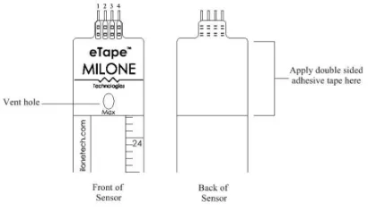
Figure 2: e-tape continuous fluid level sensor
The e-tape sensor is a solid state, continuous (multi-level) fluid level sensor for measuring levels in water, non-corrosive water based liquids and dry fluids (powders). The e-Tape sensor is manufactured using printed electronic technologies which employ additive direct printing processes to produce functional circuits. Figure 2 show the actual data sheet for this e-tape sensor.
ATMEGA32
Level Display
Continuous Fluid Level Sensor (e-tape) Motor
The e-tape sensor's envelope is compressed by hydrostatic pressure of the fluid in which it is immersed resulting in a change in resistance which corresponds to the distance from the top of the sensor to the fluid surface. The e-tape sensor provides a resistive output that is inversely proportional to the level of the liquid: the lower the liquid level, the higher the output resistance; the higher the liquid level, the lower the output resistance.
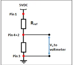
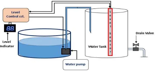
To control the level, tape sensor is attach inside the tank as figure 3. Connection the pin of e-tape sensor as shown in figure 4 and calculate the voltage of max and min water level in tank. Output voltage divider is connected to ADC microcontroller. This is important part which is to control the motor pumping unit. Control signal from board will be sent to the motor pumping circuit when liquid level at certain value or to stop the motor when under the value to prevent idling state.
Figure 3: Liquid level e-tape sensor setup inside tank
Figure 4: Simple voltage divider circuit
Figure 5: 7-segment display circuit
line digital temperatures sensor DS18B20 will be used. A seven segment display (SSD), or seven segment indicator, is a form of electronic display device for displaying decimal numerals that is an alternative to the more complex dot-matrix displays. A seven segment display is use as its name indicates level value. Fig. 5 shown the circuit for 7 segment.
Total system software written by C language includes in independent technique, where based on this technique the coding is written in separate file. There are 3 independent program files (main.c, adc.c and led.c) created in this project and named based on their function. Each file consist of two type which are the header file (*.h) and the c program (*.c). Displaying liquid level and controlling motor pumping unit is imp lamented in main routines, which is the core of system software and interrupt serve subroutines are called in it. Full diagram are shown in Figure 6 and full flow chart are shown in Fig. 7.
Figure 6: Liquid level system
3.0 RESULTS AND DISCUSSION
Table 1 show the total of pin that use in this project. Pin 0 in port A is use as ADC input. First step is needed to calibrate and find the value of voltage produce according to liquid level from the e-tape sensor. Table 2 shows the data and the relationship between voltage and level of liquid. Its show that e-tape sensor provide a voltage output inversely proportional to the level liquid.
Table 1: Total pin use in the circuit
Pin No. Pin
Name Description
PIN40 PA0 Connect the sensor output to ADC
PIN14 PD0
Connect from PD0 : PD3 to the inputs of 74LS47 from AO : A3 respectively for display LSB of level indicator
PIN15 PD1
PIN16 PD2
PIN17 PD3
PIN18 PD4
Connect from PD4 : PD7 to the inputs of 74LS47 from AO : A3 respectively for display MSB of level indicator
PIN19 PD5
PIN20 PD6
PIN21 PD7
Table 2: Calibrate data for level of liquid
Level of liquid (inches)
Voltage produce (v)
Digital number (decimal)
Digital number (hexadecimal)
7 1.56 319 13F
6.5 1.70 347 15B
6 1.80 368 170
5.5 1.87 382 17E
5 2.00 409 199
4.5 2.09 427 1AB
4 2.15 439 1B7
3.5 2.24 458 1CA
3 2.40 491 1EB
Figure 7: Flow chart
From the hardware implementation, based on the performance of the pump will work when the fluid level is low. Then after certain level (high level setting), pump is off.
4.0 CONCLUSSION
which is maximum water level measurement can be made is up to 25cm. In future works, user can add another feature like accessible through SMS.
ACKNOWLEDGEMENT
The authors would like to express deep appreciations to the Ministry of Higher Education Malaysia and Universiti Teknikal Malaysia Melaka (UTeM) for providing a PJP grant (PJP/2014/FTK(3B)/S01302), opportunity and necessary facilities to support this research work.
REFERENCES
[1] A. S. Morris, R. Langari, Measurement and instrumentation theory and application, Elsevier, (2012).
[2] W. Hongqi, L. Xia, Design of measurement and control system for oil level of wells, 2nd
International Conference on Instrumentation & Measurement, (2012).
[3] W. Zhang, Based on atmega 16 ultrasonic distance gauge, International Conference Electrical and Control Engineering (2011).
[4] H. Canbolat, A novel level measurement technique using three capacitive sensors for liquids, The Instrumentation and Measurement 58 (2009) 3762-3768.
[5] B.K. Roy, K.V. Santhosh, An intelligent instrument for measuring liquid level, The International Conference Process Automation, Control and Computing (PACC), (2011) 1-5.
[6] M. Saraswati, E. Kuantama, P. Mardjoko, Design and construction of water level measurement system accessible through SMS, 6th European Modelling Symposium, (2012).
[7] G. Betta, A. Pietrosanto, A. Scaglione, Microcontroller-based performance enhancement of an optical fiber level transducer, IEEE Instrumentation & Measurement 47 (1998) 489-493.
[8] L. Jian-Long, Meter based on ultrasonic to measure the liquid level, The Instrument Technique and Sensor 6 (2004) 21-23.
[9] L. Sun, S. Jin, L.B. Sun, Development of magnetostriction sensor for on-line liquid level and density measurement, Sixth World Congress On Intelligent Control And Automation, (2006) 5162-5166.
[10] J.D. Boon, R.M. Heitsenrether, W.M. Hensley, Multi-sensor evaluation of microwave water level measurement error, IEEE Oceans (2012) 1-8.
[12] V. Milosavljevi , Ž. Mihajlovi , V. Rajs, M. Živanov, Implementation of low cost liquid level sensor (LLS) using embedded system with integrated capacitive sensing module, The Mediterranean Conference on Embedded Computing Meco (2012).
[13] W.C. Haase, Digital measurement circuit and system using a grounded capacitive sensor, U.S. Patent (2004) 1-15.
[14] L. Consolini, G. Lini, A. Plazzi, A. Visioli, Minimum-time rest-to-rest feedforward action forpid feedback mimo systems, In IFAQ Conference In PID Control (2012). [15] K.K. Tan, R. Ferdous, S. Huang, Closed loop automatic tuning of PID controller for
nonlinier systems, The Chemical Engineering Sciences 57 (2002) 3005-3011.
[16] M.S. Ramli, R.M.T.R. Ismail, M.A. Ahamad, S.M. Nawi, M.A.M. Hussin, Improved coupled tank liquid level systems based on swarm adaptive tuning of hybrid propotional-integral neural network controller, The American Journal Of Engineering and Applied Sciences 4 (2009) 669-675.
[17] Wahyudi, M. Fadhil, M. Shazri, Robust anti-windup pid control of a couple industrial tank system, International Conference on Mechanical Engineering 2007 (ICME 2007) (2007).
[18] P. Boonsrimuang, A. Numsomran, S. Kangwanrat, Design of PI controller using mrac techniques for coupled-tanks process, The World Academy of Science, Engineering and Technology 2010 (2010) 485-490.