DEVELOPING A WIRELESS CHARGING CONCEPT VIA LOOSELY COUPLED INDUCTIVE POWER TRANSFER FOR ELECTRIC VEHICLES
CHEW CHIEN HENG
This Report is Submitted in Partial Fulfilment for the
Bachelor Degree of Electronic Engineering (Wireless Communication)
Faculty of Electronics and Computer Engineering Universiti Teknikal Malaysia Melaka
ii
UNIVERSTI TEKNIKAL MALAYSIA MELAKA
FAKULTI KEJURUTERAAN ELEKTRONIK DAN KEJURUTERAAN KOMPUTER
BORANG PENGESAHAN STATUS LAPORAN PROJEK SARJANA MUDA II
Tajuk Projek : Developing a Wireless Charging Concept via Loosely Coupled Inductive Power Transfer for Electric Vehicles
Sesi
Pengajian : 1 4 / 1 5
Saya CHEW CHIEN HENG
(HURUF BESAR)
mengaku membenarkan Laporan Projek Sarjana Muda ini disimpan di Perpustakaan dengan syarat-syarat kegunaan seperti berikut:
1. Laporan adalah hakmilik Universiti Teknikal Malaysia Melaka.
2. Perpustakaan dibenarkan membuat salinan untuk tujuan pengajian sahaja.
3. Perpustakaan dibenarkan membuat salinan laporan ini sebagai bahan pertukaran antara institusi pengajian tinggi.
4. Sila tandakan ( √ ) :
SULIT*
*(Mengandungi maklumat yang berdarjah keselamatan atau kepentingan Malaysia seperti yang termaktub di dalam AKTA RAHSIA RASMI 1972)
TERHAD** **(Mengandungi maklumat terhad yang telah ditentukan oleh organisasi/badan di mana penyelidikan dijalankan)
TIDAK TERHAD
Disahkan oleh:
__________________________ ___________________________________
(TANDATANGAN PENULIS) (COP DAN TANDATANGAN PENYELIA)
iii
I hereby declare that I have read through this report entitle “Developing a Wireless Charging Concept via Loosely Coupled Inductive Power Transfer for Electric Vehicles” and found that it has comply the partial fulfilment for awarding the degree of Bachelor of Electronic and Computer Engineering (Wireless Communication)
Signature : ………. Name : ………...
iv
I hereby declare that this report entitle “Developing a Wireless Charging Concept via Loosely Coupled Inductive Power Transfer for Electric Vehicles” is the result of my own research except as cited in the references. This report has not been accepted for any degree and is not concurrently submitted in candidature of any other degree.
Signature : ………. Name : ………...
v
ACKNOWLEDGEMENT
vi
ABSTRACT
This project aims to develop a charging method for electric vehicle via loosely coupled inductive power transfer (LCIPT). This method enables wireless power transmission from stationary power source to a moving load, which is the electric vehicle. Most of the existing products in this framework applied coupled magnetic resonance power transfer (CMRPT) method, i.e. the Qi technology. However, this method is limited to stationary charging. This project focuses on developing a wireless charging method to a movable load which is electric vehicle in our case. In this project, a prototype that capable to delivers power efficiently from a stationary power source to a moving load is developed. The prototype is designed in a small scale low power model of 12 Volt 5 Watt DC input to prove the proposed method applicable and could be widely used in future works through the evolution of wireless power transfer (WPT) technology. To be specific, in this project, Class E resonant inverter is used to convert the DC source to AC source at 1 MHz resonant frequency. Analysis is done on different configurations and setups of the transmission coils. Compensator circuit is also designed at the transmission coil to boost the power transfer efficiency. The output of the wireless power transmission is tested on DC-motorcar and LED. At the end, a prototype of this project is successfully developed.
vii
ABSTRAK
Projek ini bertujuan untuk membangunkan satu kaedah pengecasan untuk kenderaan elektrik melalui gandingan longgar pemindahan kuasa induktif (LCIPT). Kaedah ini membolehkan penghantaran kuasa tanpa wayar dari sumber kuasa setempat untuk beban yang bergerak, yang merupakan kenderaan elektrik. Sebahagian besar produk sedia ada dalam rangka kerja ini yang dikenakan ditambah resonans magnet pemindahan kuasa (CMRPT) kaedah, iaitu teknologi Qi. Walau bagaimanapun, kaedah ini adalah terhad kepada caj setempat. Projek ini memberi tumpuan kepada membangunkan kaedah pengecasan tanpa wayar kepada beban alih yang adalah kenderaan elektrik dalam kes kami. Dalam projek ini, satu prototaip yang mampu untuk menyampaikan kuasa cekap daripada sumber kuasa setempat untuk beban yang bergerak maju. Prototaip ini direka dalam model kuasa rendah kecil 12 Volt 5 Watt DC input untuk membuktikan kaedah yang dicadangkan boleh digunakan dan boleh digunakan secara meluas pada masa akan datang melalui evolusi pemindahan tenaga tanpa wayar teknologi (WPT). Dalam projek ini, Kelas E penukar salunan digunakan untuk menukar sumber DC ke AC sumber di 1 MHz frekuensi salunan. Analisis dilakukan pada konfigurasi yang berbeza dan setup gegelung penghantaran. Litar pemampas juga direka di gegelung penghantaran untuk meningkatkan kecekapan pemindahan kuasa. Keluaran penghantaran kuasa tanpa wayar diuji di DC-kereta dan LED. Pada akhirnya, prototaip projek ini berjaya dibangunkan.
viii
TABLE OF CONTENTS
CHAPTER TITLE PAGE
I INTRODUCTION
1.1. Background 1.2. Motivation
1.3. Problem Statement 1.4. Objectives
1.5. Scope
1.6. Thesis Outline
1 2 3 3 3 5
II LITERATURE REVIEW
2.1. Overview
2.2. Background Study
2.3. Inductive Power Transfer and Other Type of Wireless Power Transfer
2.4. Inverters for Wireless Power Transfer (WPT) 2.5. Voltage Regulator
2.6. Electromagnetic Coils 2.7. Compensator Circuit
6 6 8 11 14 15 16
III METHODOLOGY
3.1. Overview
3.2. Prototype Design Process Flow 3.3. Design of Push-Pull Inverter
3.4. Design of Class-E Resonant Inverter
ix 3.5. MOSFET Gate Input Signal
3.6. Design of Driver Circuit for PIC Output Signal 3.7. Design of Rectifier Circuit
3.8. Design of Voltage Regulator
3.9. Wireless Power Transmission Coil Design Method
3.10. TX-RX Transmission Coil Design and Performance Analysis 22 23 23 24 25 27
IV RESULTS & DISCUSSIONS
4.1. Class E Inverter Results
4.2. Transmission TX-RX Coil Results and Analysis 4.2.a. Experiment 1 – Circular TX-Coil
4.2.b. Experiment 2 – Elongated TX-Coil 4.2.c. Experiment 3 – Parallel Circular TX-Coil 4.3. DC-Motorcar Power Requirement Analysis 4.4. LED Load Analysis
4.5. Overall Discussions
29 33 33 36 39 41 43 44
V CONCLUSION & RECOMMENDATION
x
xi
LIST OF FIGURES
FIGURE TITLE PAGE
1.5.1 1.5.2
Prototype Track Design (Top View) Prototype Model Design (Front View)
4 4 2.3.1 2.3.2 2.3.3 2.4.1 2.4.2 2.4.3 2.4.2 2.5.1 2.5.2 2.6.1 2.7.1 2.7.2
Inductive Power Transfer Capacitive Power Transfer Acoustic Power Transfer
Push-Pull Inverter Basic Circuit Structure Class E Inverter Basic Circuit Structure Inverter / Resonant Tank Equivalent Circuit Zero Voltage Switching (ZVS)
Basic Voltage Regulator IC Basic Voltage Regulator Circuit
Electromagnetic Coils Magnetic Field Induction Series Capacitor Compensation
Parallel Capacitor Compensation
8 10 10 11 12 12 13 14 14 15 16 16 3.1.1 3.2.1 3.3.1 3.4.1 3.5.1 3.6.1 3.7.1 3.8.1 3.8.2 3.9.1
Prototype Model Operation Process Flow Block Diagram
Project Methodology Flow Chart
Push-Pull Inverter Circuit Design (LTspice)
Class E Resonant Inverter Circuit Design (LTspice) PWM 1 MHz 50% Duty Cycle Square Wave mikroC Programme Code
TC4422 PIC MOSFET Driver Circuit Design Full Wave Rectifier Circuit Design
LM317 Adjustable Voltage Regulator Circuit Design LD1117-series Fixed Voltage Regulator Circuit Design Transmission Coil Design Methods on Class E Inverter
xii 3.9.2
3.9.3 3.10.1 3.10.2
Transmission Coil Design Method 1 Transmission Coil Design Method 2
Type of Coil: Solenoid (left); Pancake (right) Illustration of Circular (left) and Elongated (right) Pancake Coil 26 26 27 28 4.1.1 4.1.2
LTspice Class E Inverter Circuit Practical Class E Inverter Circuit
29 29 4.1.3 Drain (Blue) vs. Gate (Red) ZVS [Simulation] 30 4.1.4 Drain (Blue) vs. Gate (Purple) ZVS [Practical] 30
4.1.5 Drain (Blue) vs. Capacitor (Red) [Simulation] 31 4.1.6 Drain (Blue) vs. Capacitor (Purple) [Practical] 31 4.1.7 Drain (Blue) vs. Load (Red) [Simulation] 32 4.1.8 Drain (Blue) vs. Load (Purple) [Practical] 32
4.2.1 TX-Coil Track Installation 34
4.2.2 4.2.3a 4.2.3b
Number of Coil Turns vs. Efficiency Elongated TX-Coil Structure
Elongated TX-Coil
35 36 36 4.2.4 Elongated TX-Coil (a = 50 cm) Result. (Blue) vs.
(Purple)
38
4.2.5a 4.2.5b 4.2.6
Parallel Circular TX-Coil Structure Parallel Circular TX-Coil
Parallel Circular TX-Coil without Core Result. (Blue) vs. (Purple)
39 39 40
4.2.7 Parallel Circular TX-Coil with Core Result. (Blue) vs. (Purple)
40
4.3.1 4.4.1 4.5.1 4.5.2
DC-Motorcar used for Project Prototype Elongated PCB TX-Coil
Magnetisation (B-H) Curve
Better Design of TX-Coil Instalment
xiii
LIST OF TABLES
TABLE TITLE PAGE
4.1.1 4.2.1 4.2.2
4.2.3
4.3.1
Class E Inverter Voltage Outputs
Transmission Coil Efficiency Test Analysis
Elongated TX-Coil Transmission Analysis (Current Overloaded)
Elongated TX-Coil Transmission Analysis (Current Not Overloaded)
DC Power Supply Settings on DC-Motorcar Analysis
33 34 37
38
1
CHAPTER I – INTRODUCTION
1.1 Background
Fossil fuels and natural gases consumption have been increasing tremendously over the centuries since the invention of internal combustion engine (ICE) for automobile dated back to 1886, the first petrol or gasoline powered Benz Patent-Motorwagen, invention of Karl Benz. The combustion of petrol and gasoline releases harmful gases to the atmosphere and pollutes the environment. Despite the effort to reduce the pollution with instalment of filters and engine-fuel combustion efficiency enhancement via the advent of technologies over the era, the fact that pollutants are still being emitted to the atmosphere remains. On top of that, fossil fuels and natural gases are non-renewable resources and are estimated to be depleted at the end of the 21st century [1]. Hence, alternative renewable energy resources such as electrical energy especially are being utilized to curb the problem in the auto-mobile industry.
Electric vehicle (EV) is the alternative solution to reduce fuel consumption and pollution rate. The invention of electric vehicle is attributed to various people. A Hungarian inventor, Ányos István Jedlik invented the early type of electric motor in the year 1828 and created a small model car powered by that motor later. A Vermont blacksmith, Thomas Davenport built a similar small model electric car powered by electrified circular track [2].
2 However, the availability of charging stations for EV is low and it takes a long time to completely charge the EV. This problem could be eliminated with wireless power charging technology via the loosely coupled inductive power transfer (LCIPT) method. Through this method approach of wireless power transfer (WPT) technology, the EV could be charged even at the motion, providing flexibility, convenience and freedom from being bounded by plug-in power cords at charging point. To current date of WPT technological level, LCIPT is still in the development stage and not ready for high power applications yet. Thus, this project focuses to develop the concept of LCIPT in small scale low power model to prove the applicability of LCIPT in EV charging. With further improvements, the concept of motional EV charging could be realized.
1.2 Motivation
This project is inspired by the recent achievement of the Qi wireless charging technology in the inductive power transfer (IPT) method. Qi (pronounced as “chee”) wireless charging is a new standard developed by the Wireless power Consortium for charging mobile electronics without conductive contact. This technology is capable of transferring power wirelessly over distance up to 4cm (1.6 inches). This technology has been successfully applied on mobile phones and some other low power electronics. However, this technology is limited to stationary charging.
3
1.3 Problem Statement
Electric vehicle is becoming the preference of the consumers and statistic shows the demand for electric vehicle is growing through the years. The major down point with electric vehicle today is the charging issue. The existing method which used coupled magnetic resonance power transfer (CMRPT) has its limitations – time consuming and stationary charging. Furthermore, the availability of the electric vehicle charging station is very low. But this problem could be overcome with the loosely coupled inductive power transfer (LCIPT) method.
However, a major problem with loosely inductive power transfer (IPT) is the efficiency issue. The closely coupled IPT system enables high power transmission. But, a loosely coupled IPT system has lower capability of power transmission and therefore it reduces the efficiency significantly. Hence, Compensation in secondary coil windings should be implemented to solve this issue.
1.4 Objectives
1. To develop small scale low power electric vehicle prototype to represent the charging concept using loosely coupled inductive power transfer method. 2. To design a compensation circuit to improve the efficiency of such circuits. 3. To analyse the performance of the developed prototype.
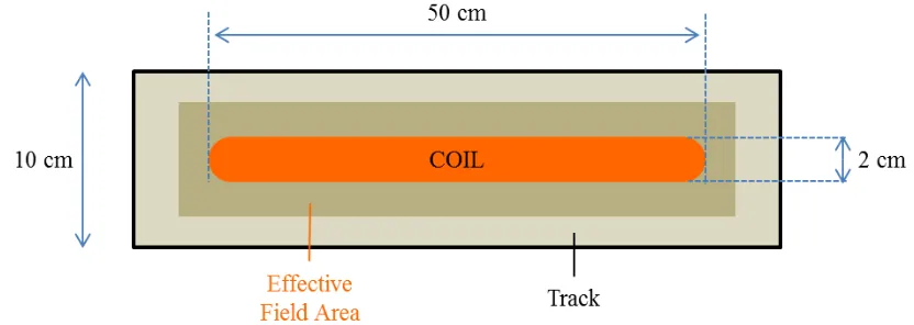
1.5Scope
4 rectifier are designed at the receiver (moving load) as the power loss compensator as it is a highly efficient switching power amplifier that can be used at high frequencies. Simulations are done using the LTspice software to analyse the performance of the circuits. The conceptual design of the proposed method is shown in Figure 1.5.1 and Figure 1.5.2.
Figure 1.5.1 – Prototype Track Design (Top View)
5
1.6Thesis Outline
CHAPTER I introduced the background regarding the project, discussed about the motivation that inspired the author to do research on the project, the problem encountered by the existing technology regarding the project, the objectives of the project, and the target scope in this research.
CHAPTER II discussed about the literature review on the project including the background study of electric vehicle and existing charging systems, the various method of wireless power transfer, and research on elements used in developing the project prototype.
CHAPTER III described on the methodology about the flow on how the project is done. The prototype operation and designs of its elements are described in detail. CHAPTER IV discussed about the results of the project research and analysis. Detailed analysis is performed on several factors that affect the wireless power transmission performance.
6
CHAPTER II – LITEREATURE REVIEW
2.1 Overview
The electric vehicle (EV) charging system which uses inductive power transfer (IPT) technique is not a newly found technique of wireless power transfer (WPT) technology. In fact, IPT is the first technique used for WPT. The existing method of IPT technique uses closely coupled magnetic resonance power transfer has limitations. The alignment of the transmitter and receiver affects the power transmission efficiency. Besides that, the charging rate on par with current technology is low. There are many researches done and designs made to curb this issue. In contrast, this project work on the new approach of the IPT technique via loosely coupled IPT (LCIPT) and aims to prove the concept is applicable to electric vehicle charging system. There are many researches have been done on IPT. However, most of the researches done are on the closely coupled IPT and lesser on loosely coupled IPT (LCIPT). Moreover, most research are described theoretically and only simulated as the results. Practically, the system only applied on the EV charging stations. Topics to be discussed covered in this chapter are about the electric vehicle (EV) charging systems, IPT and other WPT methods performance analysis, and the circuits used in the IPT systems such as supply inverters and efficiency compensator circuits.
2.2 Background Study
There are many researches done on Vehicle-to-Grid (V2G) technology, which is similar and related to this project but only the selected few will be discussed. These V2G researches [4 – 7] are about electric vehicle (EV) charging on the road in the energy distribution grid through slightly different method of approach of IPT technique. Similarly, these researches worked on simulations to analyse the impact of their systems on large scale integration of operation.
7 Point America to increase the number of EV massively. To accommodate this massive integration of EV, infrastructure such as charging station needs to be established properly. Paper [4] discussed the impact analysis of EV charging system via simulations on MATLAB/Simulink. Several techniques of design including non-linear battery model, bi-directional converter model, and loading level distribution network IEEE 13-node system model are tested. The results show that this EV charging system is capable of delivering 1 MW power and achieving 100% line profile in IEEE 13 node system. The advantage of this system is the distributed generators installed near EV charging system can prevent overloading in the primary equipment. By increasing the charging capacity, the loading level could reach the rated capacity of certain line segment in distribution network. The author stated that this design can be further improved by improving the power factor of the charging station, energy storage capacity and re-direct power flow through local distribution coordination.
Similar to [7], authors in [8] discussed about the importance of EV in term of sustainability and green towards environment but through different method of approach. Paper [9] focused on innovative on-road dynamic wireless charging system called OLEV design concept. The OLEV design concept is about fast charging in range of 100 kW and optimizing magnetic flux field for higher power transfer efficiency of the system.
In contrast to [7] and [8], authors in [9] focused on designing an experimental control system of EV charging system composed on photovoltaic (PV) array. The control system extracts maximum power from the PV array and manages the power flow of the charging state according to the constraints of the power grid. Instead of designing on the transmission circuit, the authors of this paper focused on the control system of the wireless power transmission to optimize the usage of power according to the need of the EV charging system.
8 MATLAB/Simulink and the system feasibility is proven. With this design, the power consumption could be optimized even further.
Referring to the papers [4 – 8] discussed above, it can be deduced that the designs are made to improve the efficiency of WPT technology and optimize the power utilisation of the power grid. These designs are discussed theoretically and results are only simulated. Practical implementations are yet to be applied. Justifying these papers, sustainability of this project can be achieved and large scale practical implementation is possible. This background study shows that there is more than one way to improve and optimise the WPT technology via IPT technique. Thus, this project takes on a new method of approach rather than improving the existing methods.
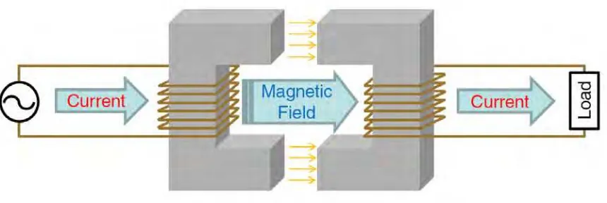
2.3 Inductive Power Transfer and Other Type of Wireless Power Transfer
Wireless power transfer (WPT) is a technology that transfers power without the direct connection contact of conductors (contactless) via electromagnetic resonance coupling. WPT technology provides green benefits towards the environment as electric energy is a green and renewable energy. With the implementation of WPT in electric vehicle (EV), pollution can be reduced. Besides that, WPT eliminates unnecessary cords that bound electrical and electronic devices to power source point and thus, provides convenience and freedom to users. The capability of WPT offers flexible coupling for universal range of devices from low to high power devices. Moreover, WPT technology is capable to authenticates and adapt to different and multiple loads. There a few transmission method which are inductive power transfer (IPT), capacitive power transfer (CPT) and acoustic power transfer (APT), a new method in development which uses wave and vibration [9 – 12].
9 the transmission is improved with resonance coupling at high frequency. The conventional existing method of IPT via closely coupled magnetic resonance is capable of transmitting high power but has range limitation and is bounded to proper alignment for optimum efficiency. The loosely coupled IPT (LCIPT) method provides flexibility and freedom to users as the LCIPT enables moving load (mobile) power transmission from stationary power source. Besides that, LCIPT also enables unlimited number of output devices connection from one single power source [13 – 15]. Figure 2.3.1 shows the power transmission concept of the IPT approach.
Figure 2.3.1 – Inductive Power Transfer
10
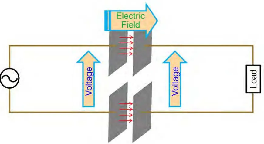
Figure 2.3.2 – Capacitive Power Transfer
Acoustic Power Transfer (APT) is a new power transmission technique of WPT technology. APT uses acoustic waves and vibration to transmit power. For a new and rising technology, APT covers a big dimension as power is transferred via acoustic waves and vibrations. The existing researches on APT are mostly on ultrasonic coupling using piezoelectrics. APT can be very powerful WPT power transmission technique. This is because APT covers a vase factors that affect its performance including the design, material, type of transmission, transmission medium and surrounding ambient interference. APT is capable to transmit high power over a long distance. However, to current technological limitations, APT still have long way to go before it can realize the ultimate WPT technology [19 – 20]. Figure 2.3.3 shows the power transmission concept of APT approach.
11
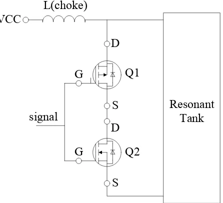
2.4 Inverters for Wireless Power Transfer (WPT)
In wireless power transfer (WPT), inverters play important role to supply stable high frequency power to the circuit for transmission. As in this project, the inductive power transfer (IPT) wireless power transmission is best transmitted via AC power. But, DC power supply input is more stable and much cheaper than AC power. Thus, a high power factor and efficient inverter is needed to convert the input DC power supply into AC power for magnetic flux generation in the transmitter coils. In this project, two types of inverter, the push-pull inverter and the class-e inverter are selected to compare their performances on the prototype and the most suitable one will be chosen. In this project, both push-pull and class-e designs operate as switching mode regulator with desired frequency set by the control signal circuit. Figure 2.4.1 and Figure 2.4.2 show the Push-Pull and Class E inverters respectively. The resonant tank as shown in Figure 2.4.3 resonates with the frequency output from the switches to produce stable AC power.
G G
D
S D
S Q1
Q2 L(choke)
VCC
signal Resonant Tank