WIRELESS POWER TRANSFER FOR ELECTRIC VEHICLES
AMALUDDIN BIN ZAINUDDIN
This Report Is Submitted In Partial Fulfillment of Requirement for the Bachelor Degree of Electronic Engineering (Computer Engineering)
Fakulti Kejuruteraan Elektronik Dan Kejuruteraan Computer Universiti Teknikal Malaysia Melaka
ii
UNIVERSTI TEKNIKAL MALAYSIA MELAKA
FAKULTI KEJURUTERAAN ELEKTRONIK DAN KEJURUTERAAN KOMPUTER
BORANG PENGESAHAN STATUS LAPORAN
PROJEK SARJANA MUDA II
Tajuk Projek : WIRELESS POWER TRANSFER FOR ELECTRIC VEHICLES Sesi Pengajian : 1 4 / 1 5
Saya AMALUDDIN BIN ZAINUDDIN
(HURUF BESAR)
mengaku membenarkan Laporan Projek Sarjana Muda ini disimpan di Perpustakaan dengan syarat-syarat kegunaan seperti berikut:
1. Laporan adalah hakmilik Universiti Teknikal Malaysia Melaka.
2. Perpustakaan dibenarkan membuat salinan untuk tujuan pengajian sahaja.
3. Perpustakaan dibenarkan membuat salinan laporan ini sebagai bahan pertukaran antara institusi pengajian tinggi.
4. Sila tandakan ( √ ) :
SULIT*
*(Mengandungi maklumat yang berdarjah keselamatan atau kepentingan Malaysia seperti yang termaktub di dalam AKTA RAHSIA RASMI 1972)
TERHAD** **(Mengandungi maklumat terhad yang telah ditentukan oleh
organisasi/badan di mana penyelidikan dijalankan)
TIDAK TERHAD
Disahkan oleh:
__________________________ ___________________________________
(TANDATANGAN PENULIS) (COP DAN TANDATANGAN PENYELIA)
Tarikh: ……….. Tarikh: ………..
iii
“I declare this report in my own work except for summary and quotes that I have mentioned its sources”
Singnature :
Author’s Name : AMALUDDIN BIN ZAINUDDIN
iv
“I hereby declare that I have read this report and in my opinion this report is sufficient in terms of the scope and quality for the award of Bachelor of Electronic Engineering
(Computer Engineering) With Honours”
Signature :
Supervisor Name : DR NORIHAN BINTI ABDUL HAMID
v
Dedicated to My Beloved Parents,
Zainuddin Bin Mah Jilis and Rohaya Binti Alias, My supportive supervisor,
Dr Norihan Binti Abdul Hamid My lovely siblings,
vi
ACKNOWLEDGEMENT
First of all, I would like to take this opportunity to express my deepest gratitude to my project supervisor, Dr Norihan Binti Abdul Hamid for her guidance, encouragement and endurance the whole course of this project. It is indeed my pleasure for her support, invaluable advices and enthusiastic toward my project. Your advice on both research as well as on my career have been priceless.
My special gratitude is to my beloved family, especially my parents Zainuddin Bin Mah Jilis and Rohaya Binti Alias for their fullest support throughout the year study in Technical University Malaysia Melaka (UTeM). Because of them, I am the person who I am today, for all their moral support all these while so that I will be to complete project successfully. Not forget for my brother, Ahmad Anwar Bin Zainuddin for his guidance in completing this project.
vii
ABSTRACT
viii
ABSTRAK
ix
TABLE OF CONTENTS
CHAPTER TITLE PAGE
PROJECT TITLE I
REPORT STATUS VERIFICATION FORM II
DECLARATION III
SUPERVISOR DECLARATION VI
DEDICATION V
ACKNOWLEDGEMENT VI
ABSTRACT VII
ABSTRAK VIII
TABLE OF CONTENT IX
LIST OF TABLES XIII
LIST OF FIGURES XIV
LIST OF APPENDICES XVII
I INTRODUCTION
1.1 Introduction 1
1.2 Problem Statement 3
1.3 Objectives 4
1.4 Scope of projects 4
x
II LITERATURE REVIEW
2.1 Introduction 6
2.2 Wireless Power Transfer Principle 7
2.2.1 Microwave Principle 7
2.2.2 Laser Principle 9
2.2.3 Inductive Resonant Coupling Principle 10
2.2.3.1 Concept of Electromagnetism 11
2.2.3.2 Electromagnetic Induction 12
2.2.3.3 Resonance Frequency 14
2.2.3.4 Definition of Inductor 15
2.3 Comparison of three Principle
In Wireless Power Transfer 16
2.4 Chapter Summary 18
III RESEARCH METHODOLOGY
3.1 Introduction 19
3.2 Electric Vehicle Charging System 20
3.2.1 Circuit Diagram 21
3.3 Methodology and Project Development 22
3.3.1 Methodology Flowchart 23
3.3.2 Circuit Design 25
3.3.3 Simulation and Analysis Circuit on
Breadboard 26
xi
3.3.5 Printed Circuit Board (PCB)
Development
3.3.5.1 Layout Design 29
3.3.5.2 Etching Process 30
3.3.5.3 Soldering Process 30
3.3.5.4 Traoubleshooting 30
3.4 Electric Vehicle Prototype Development 31
3.5 Charging Indicator 32
3.6 Component and Device used in Designed Circuit 33
3.7 Chapter Summary 36
IV RESULT AND DISCUSSION
4.1 Introduction 37
4.2 Inductance and Capacitance Value Consideration 38
4.3 Experimental Set Up 40
4.4 Result and Analysis 41
4.4.1 Correlation between distances of transmitter
Circuit and receiver circuit 41
4.4.2 Correlation between of input power
(via transmitter circuit) and output power
(via receiver circuit) in fixed distance of 0 cm 44
4.4.3 Correlation between of input power
(via transmitter circuit) and output power
xii
4.4.4 Correlation between of input power
(via transmitter circuit) and output power
(via receiver circuit) in fixed distance of 10 cm 48
4.4.5 Relationship between of input power
(via transmitter circuit) and output power
(via receiver circuit) in fixed distance of 15 cm 49
4.5 Prototype 50
4.6 Prototype with a different obstacle between
transmitter coil and receiver coil 51
4.7 Result of the circuit prototype demonstration 53
4.8 Electric Vehicle Prototype 54
4.9 Charging Indicator 55
4.10 Chapter Summary 56
VI CONCLUSION AND RECOMMENDATION
5.1 Conclusion 57
5.2 Recommendation 59
REFERENCES 60
xiii
LIST OF TABLES
TABLE TITLE PAGE
xiv
LIST OF FIGURES
FIGURE TITLE PAGE
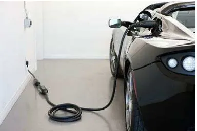
1.1 Example of electric car using plug in cable 3
2.1 Block Diagram of Microwave System 8
2.2 Magnetic field around the wire/conductor 12
2.3 Transformer 13
3.1 Block diagram of the system 20
3.2 Schematic design of transmitter circuit 21 3.3 Schematic design of receiver circuit 21
3.4 Methodology flowchart 23
3.5 Methodology flowchart 24
3.6 Circuit testing using breadboard 26
3.7 Circuit tested using multimeter to check functionality 26 3.8 Transmitter and Receiver coil manufacturing 28 (Multilayer air core Inductor)
3.9 Layout design of transmitter circuit 29
3.10 Layout design of receiver circuit 29
3.11 Acrylic sheet 31
xv
3.13 Charger module with rechargeable battery 31 3.14 Schematic of LCD Circuit Diagram 32
3.15 MAX17043 Fuel Gauge 33
3.16 Toroidal core inductor 34
3.17 IRFZ44N Power MOSFET 35
3.18 Enameled Cooper Wire 35
4.1 Frequency produced by an oscillator 38 4.2 Completed prototype model of wireless 40 power transfer system
4.3 Relationship between output voltages (V) and 41 output current (mA) versus distance
4.4 Relationship between output power (W) and 42 output current (mA) versus distance
4.5 Relationship between output voltages (V) and 44 output current (mA) versus input voltage (V)
4.6 Relationship between input voltages (V) versus 46 efficiency, ŋ % at the distance of 0 cm
4.7 Relationship between output voltages (V) and 47 current (mA) versus input voltage (V) at the
distance of 5 cm
4.8 Relationship between output voltages (V) and c 48 urrent (mA) versus Input Voltage (V) at the
distance of 10 cm
4.9 Relationship between input voltages (V) and 49 current (mA) versus input voltage (V) at the
xvi
4.10 LED light up brightly when the coil is closer 50 4.11 LED dim slightly when the coil is far each other 50
4.12 A pack of soil 51
4.13 A pack of water 51
4.14 Thick book 51
4.15 Correlation between output voltages with 52 different barrier versus distance
4.16 The output of receiver can be used as charger 53 of smartphone
4.17 An electric vehicle prototype integrated with 54 wireless power transfer device
xvii
LIST OF APPENDICES
NO TITLE PAGE
A Table of Collected Data 62
G Source Code of Charging Indicator 68
CHAPTER 1
INTRODUCTION
1.1 Introduction
2
There is a demand for wireless power transfer system. Nowadays, the development of wireless charging for smartphone is rapidly increase in market. The drawbacks of the system is the smartphone are need to attach charging plate but cannot lift it while charging.
In this project, the proposed wireless power transfer technique based on inductive resonance coupling method. When AC power has been supplied through a coil, magnetic field will be generated around the coil. At the moment, if another coil put aside it, induced current will produced and caused the magnetic field will also appear around the other coil. This is the reason that wireless power transfer is set up between two coils. Energy will be transfer when both coils will have same resonant frequency.
Many of the contactless feed systems are based on the electromagnetic induction’s principle. Small distance wireless power transfer is demonstrated through used of induction. Knowledge of electric circuit logic and electromagnetic theory is important to realize the practical design. Knowledge of electric circuit logic and electromagnetic theory is important to realize the practical design.
3
1.2 Problem Statement
Current technologies only allow electric vehicles to be charged through plug-in cable. However, the problem occurs when the user need to find the charging point and the charging cable is lost or damaged. This project is about designing a wireless power transfer for electric vehicles. The concept of this project is suitable for any electric vehicles such as bus, car and light train. It will prepare a new convenient way to recharge the battery of the electric vehicles rather than using the traditional plug-in cable.
With the implementation of wireless power transfer (WPT) in order to charge the electric vehicle, there is no physical connection or contact between the vehicles and the power supply. The process is fully automated, whereby no human handling works are required to perform the charging process. Even though wireless power transfer concept is well developed and has been applied in industrial application, but its applications in the transport sector are still emerging.
[image:20.612.239.431.564.692.2]Furthermore, another serious problem occurred with current plug in cable for electric vehicles is people tend to get an electrical shock if the cable system is damaged. With wireless charging approach for electric vehicle can prevent this incident happen because no wire or cable is required and it’s transfer in electromagnetic form, so that, people will not get electrical shock in this kind of energy transfer.
4
1.3 Objectives
The objectives of this project is:
To study and investigate on wireless power transfer. A technique used in my research is an inductive resonance coupling method.
To identify how many power (voltage and current) could transmit from primary coil (source) to a secondary coil (load).
To design the wireless power transfer for electric vehicles by using the concept of inductive resonance coupling method. To prove it, a prototype will be built.
1.4 Scope of project
This research focus on developing a new approach of electrical charging using wireless power transfer.
Study about wireless power transmission using the inductive resonance coupling method.
Implement the receiver and transmission circuit simulation into the prototype.
Develop the electric vehicles wireless power transfer devices.
Develop the charging indicator using LCD display.
5
1.5 Thesis Outline
This outline is divided into five chapters to provide reader to understand the whole project. It is organized as follows:
Chapter 1, Introduction, covers the overview of the project.
Chapter 2, Literature Review and Background Studies, all the project theory,
perspective, methods that used to solve problem and any hypothesis that related in order to design the appropriate circuit.
Chapter 3, Research Methodology, the proper procedure in designing and
manufacturing of the system is presented.
Chapter 4, Result and Discussion, the result of all experiments is presented. The
experimental result is discussed and analyzed for future improvement.
Chapter 6, Conclusions and Recommendations, the conclusions of the
CHAPTER 2
LITERATURE REVIEW
2.1 Introduction
7
2.2 Wireless Power Transfer Principle
The wireless power transfer is a technology of no wire included in terms of transfer the energy. Concept of wireless power transfer has been discovered widely since Nikola Tesla carried out his first experiment about pursuing his idea on wireless lighting and electrical distribution after successfully invent an alternating current [1]. They are many methods used in the wireless power transfer which are microwave, laser, and inductive resonance coupling method.
2.2.1 Microwave Principle