MULTIPLE WIRELESS POWER TRANSFER SYSTEM
SAIDAH BINTI MUHTAR LUBIS
i
MULTIPLE WIRELESS POWER TRANSFER SYSTEM
SAIDAH BINTI MUHTAR LUBIS
This Report is Submitted in Partial Fulfillment of the Requirement for the Bachelor Degree in Electronic Engineering (Wireless Communication) With Honours
Fakulti Kejuruteraan Elektronik dan Kejuruteraan Komputer Universiti Teknikal Malaysia Melaka
v
DEDICATION
vi
ACKNOWLEDGEMENT
I am grateful to ALLAH S.W.T for the good health and wellbeing that were necessary to complete this thesis report.Alharndulillah, all Praise to thank to Allah S.W.T the Almighty for giving me the Rahmah to finish my project successfully. I would like to take this golden opportunity to express my appreciation and heartfelt gratitude to my supervisor, Eng. Noor Badariah Binti Asan for the opportunity given to me to do this project and for his belief. I really appreciate her guidance from the initial to the final level that enabled me to develop an understanding of this research thoroughly. Thank you very much for her endless support and ideas, during which she has been patiently supervising my progress and encouraged me to do this project in the right way. With full of hope, Allah SWT bless Her and family.
My sincere thanks go to all lecturers and members of the staff of the Faculty of Electronics and Computer Engineering, UTeM, who helped me in many ways and made my education journey at UTeM pleasant and unforgettable. This three years experience with all you guys will be remembered as an important memory for me to face the new chapter of life as an engineer.
vii
have become now. I cannot find the appropriate words that could properly describe my appreciation for their devotion, support and faith in my ability to achieve my dreams. Not to forget to all my supported siblings and my big family. I also would like to express special thanks to all my friends for their valuable information, various suggestions in improving the project and their cooperation towards the success of this project.
viii
ABSTRACT
ix
ABSTRAK
x
TABLE OF CONTENTS
CHAPTER CONTENT PAGE
PROJECT TITLE i
DECLARATION STATUS OF REPORT FORM ii
DECLARATION iii
SUPERVISOR DECLARATION iv
DEDICATION v
ACKNOWLEDGEMENT vi
ABSTRACT viii
ABSTRAK ix
TABLE OF CONTENTS x
LIST OF TABLE xiv
LIST OF FIGURE xv
LIST OF APPENDIX xviii
I INTRODUCTION
1.1 Project Background 2
1.2 Project Objectives 4
1.3 Problem Statement 5
1.4 Scope of Project 6
1.5 System Operation 7
1.6 Organization of the Report 8
xi
II LITERATURE REVIEW
2.1 Summary of Previous Project 10
2.2 Historical Background 14
2.3 Inductive coupling 16
2.3.1 Magnetic Field Due To Moving Charges
And Electric Currents 18
2.3.3 Inductive Charging 19
2.3.4 Resonant Frequency 20
2.3.5 Resonant Inductive Coupling 21
2.3.6 Coupling Factor 23
2.3.7 Quality Factor 24
2.3.8 General Expression for Transformer Efficiency 25 2.4 Nominal Specifications for Charging a Battery
of Mobile Phone 25
2.5 The Specification for Efficient Power Charging 29 2.5.1 The Wireless Power Consortium 29
2.5.2 Electromagnetic Shielding 31
III METHODOLOGY
3.1 Planning 34
3.1.1 Data Collection 34
3.1.2 Hardware and Software Requirement 35
3.2 Simulation 37
3.3 Layout Design 38
3.4 Implementing 39
3.4.1 Project Board Circuit (PCB) 39
3.5 Checking 42
3.6 Analysis 42
3.7 Development of a Multiple Wireless Power Transfer 43
3.7.1 Transmitter Circuit 44
xii
3.8 Flowchart of Methodology Process 51
IV RESULT AND DISCUSSION
4.1 Implementation 54
4.2 Simulation Results 56
4.2.1 Transmitter Circuit 56
4.2.2 Receiver Circuit 58
4.3 Printed Circuit Board Development 60
4.3.1 The PCB Layout of Transmitter Circuit 61 4.3.2 The PCB Layout of Receiver Circuit 62
4.4 Hardware construction 62
4.4.1 Designing Copper Coil for Transmitter
and Receiver Circuit 62
4.4.2 Circuit Construction 65
4.4.3 Development Of Prototype 66
4.5 Measured Result Analysis 67
4.6 Troubleshoot circuit 69
4.7 Discussion 71
V CONCLUSION AND RECOMMENDATION
5.1 Conclusion 72
xiii
REFERENCES 74
APPENDIX A 76
APPENDIX B 77
APPENDIX C 85
APPENDIX D 88
APPENDIX E 89
xiv
LIST OF TABLES
NO TITLE PAGE
2.1 Nominal Specifications For Lithium-ion Rechargeable Cell 27
3.1 The Dimensions of The Primary Coil 48
3.2 The Specification of 23 AWG Wire 48
4.1 Output Voltage of Transmitter Circuit by Simulation 58
4.2 Induced Voltage of Receiver Circuit 60
4.3 The Analysis in Designing a Coil 63
4.4 Input and Output of Coils 67
xv
LIST OF FIGURES
NO TITLE PAGE
1.1 Simplified Drawing of Condition for Wireless
Power Transfer to Mobile Devices 3
1.2 Scope of Project 6
1.3 Process of Multiple Wireless Power Transfer System 7 2.1 Block Diagram of the Contactless Charging System 11
2.2 Coupled Model 11
2.3 Primary Side with Reflected Impedance 12
2.4 Input Impedance Spectra for Different Couplings Showing 13 Two Typical Resonances
2.5 Distance Impacts Coil to Coil Efficiency 14
2.6 Arrangement of a Wireless Inductive Power Transmission System 17
2.7 Right Hand Grip Rule 18
2.8 Resonant Frequency 20
2.9 Resonant Coupled Windings with Resonant Capacitors 21
2.10 Strongly Coupled Transformer 24
2.11 Inductive Charging 26
2.12 Equivalent Circuit Charging Li-Ion Cell 28 2.13 Current and Voltage of a Li-Ion Cell Charging Using CC-CV Method 28
2.14 � Logo 29
2.15 Member Companies of WPC 29
2.16 Typical Wireless-Power Functional Diagram 30
3.1 System Development Life Cycle (SDLC) Phase 32
3.2 Methodology 33
xvi
3.4 Receiver Circuit Diagram 36
3.5 Simulation Results by Multisim Software 37
3.6 The Fabrication Process 41
3.7 Block Diagram of Multiple Wireless Power Transfer System 43
3.8 Power Conversation Unit 44
3.9 The Adapter 12V DC 44
3.10 MOSFET IRFZ44N 46
3.11 Half Bridge Inverter 46
3.12 The Simple Parallel Resonant Circuit 47
3.13 Primary Coil Design 47
3.14 AWG Coil 48
3.15 Receiver Side 49
3.16 A Full-Wave Rectifier Circuit Using 4 Diodes 49
3.17 LM7805 Pinout Diagram 50
3.18 Flowchart of Final Year Project 53
4.1 Step How to Use The System 55
4.2 AC Signal Resulting In a Form of Triangle Wave 57
4.3 Transmitter Circuit 57
4.4 Output Waveform across Primary Coil in Transmitter Circuit 58
4.5 Receiver Circuit 59
4.6 Output Waveform across Secondary Coil in Receiver Circuit 59
4.7 Simulation Output for Receiver Circuit 59
4.8 PCB Layout of Transmitter Circuit 61
4.9 Back View of Transmitter Layout 61
4.10 Front View of Transmitter Layout 61
4.11 Back View of Receiver Layout 62
4.12 Front View of Receiver Layout 62
4.13 Designing Copper Coil for Transmitter and Receiver Circuit 63 4.14 Relationship between Number of Turns and Induced Voltage 64 4.15 Relationship between Diameter of Designed Coil and Induced Voltage 64
4.16 Transmitter Module 65
4.17 Receiver Module 65
xvii
4.20 The Analysis of Range to Charge a Device 68
4.21 Troubleshoot on Receiver Circuit 69
4.22 Dropping of Input Voltage 69
xviii
LIST OF APPENDIX
NO TITLE PAGE
A Gantt Chart 76
B IRFZ44N Datasheet 77
C LM7805 Datasheet 86
D Measured Inductance and Resonant Frequency 89
E Guidelines for MOSFET Selection 90
1
CHAPTER 1
INTRODUCTION
New technologies emerge each and every day to make our life simpler. Despite all these, we still rely on the classical and conventional wire system to charge our everyday use low power devices such as mobile phones, digital camera etc. and even mid power devices such as laptops. The conventional wire system creates a mess when it comes to charging several devices simultaneously. It also takes up a lot of electric sockets and not to mention the fact that each device has its own design for the charging port. At this point a question might arise, “What if a single device can be used to charge these devices simultaneously without the use of wires and not creating a mess in the process?” The solution to all these dilemmas lies with inductive coupling, a simple and effective way of transferring power wirelessly
2
of the main purpose of this project is to compare different wireless power transfer development against each other’s and do enhancement on the current WPT system.
1.1 Project Background
Wireless Power Transmission (WPT) is the efficient transmission of electric power from one point to another trough air without the use of wire or any other substance. This can be used for applications where either an instantaneous amount or a continuous delivery of energy is needed, but where conventional wires are unaffordable, inconvenient, expensive, hazardous, unwanted or impossible. The power can be transmitted using inductive coupling for short range, resonant induction for mid-range and electromagnetic wave power transfer for high range. This project will be developed by using near field or non-radiative method which is for mid-range. Charging low power devices and eventually mid power devices by means of inductive coupling could be the next big thing
Multiple wireless power transfer described in this project is motivated by the potential application of resonant inductive coupling as a means for wireless power transfer from a source coil to multiple receivers. Resonance inductive coupling technology has been implemented with biomedical and consumer electronics applications that demand higher power levels than previous wirelessly powered devices [1], [2], [3]. As the power levels increase, efficiency and range become important design considerations because these criteria determine the required amount of power transmitted to sufficiently power a load. Magnetic resonance coupling technology has been implemented with biomedical and consumer electronics applications that demand higher power levels than previous wirelessly powered devices. The industry realizes the demand for wireless power charging where mobile devices can be charged without the need for connecting wires.
3
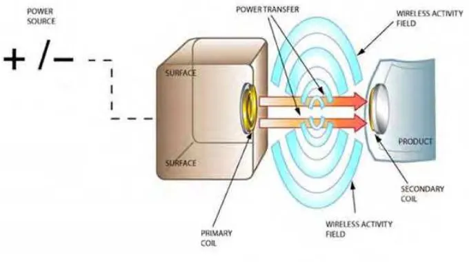
[image:22.595.148.488.217.407.2]be found in the electric toothbrush [4]. The frequency at which the device transfers power between the transmitter and receiver is dependent on the size of the coils. The higher the frequency at which the device is transmitting, the smaller the transmitting and receiving coils must be. Figure 1.1 shows the simplified drawing of condition for wireless power transfer to mobile devices where primary components in any WPT system are the coils.
Figure 1.1: Simplified Drawing of Condition for Wireless Power Transfer to Mobile Devices
The system is broken into two parts, the transmitter circuit which provides power for wireless transfer and the receiver circuit, which is the mobile device that consumes the power. The power transmitter circuit contains the primary coil, the series resonant capacitor and a DC to AC inverter that inverters the DC power supply into the AC voltage needed to induce a magnetic field between the two coils. The power receiver circuit contains the secondary coil, a parallel resonant capacitor and an AC to DC converter. The primary and secondary coils form two halves of a resonant transformer. To demonstrate that power was successfully transferred wirelessly, a mobile phone was charged and there are multiple loads in wireless power transfer systems. The amount of power transmitted and effectively received will depend on how well the coils are designed.
4
which induces a voltage across the terminals of a secondary coil, and thus transfers power to a load. This mechanism, responsible for power transfer in a transformer, where the magnetic field is typically confined to a high permeability core, also functions when the region between the primary and secondary coils is simply air. Inductive coupling without high permeability cores is used, for example, to power RFID tags and medical implants [5]. A common technique for increasing the voltage received by the device to be powered is to add a parallel capacitor to the secondary to form a resonant circuit at the operating frequency [6], [7].
1.2 Project Objectives
The main objective of this project is to build a multiple wireless power transfer. In order to make this project successful, the objectives have been declared these objectives must be achieved in completing this project. Objectives are a guidance of any project, so the objectives have been listed below.
i. To design and construct a method to transmit wireless electrical power through space.
ii. To design multiple port wireless power transfer system over range of few centimeters transmission distance using mid range technology.
iii. To develop a system of wireless power transfer for multiple small receivers iv. To study a system that was capable of charging a mobile phone using the
5
1.3 Problem Statements
There are several problems based on recent way of wireless power transfer. Firstly, today most rechargeable, portable electronic devices comes with their own proprietary charger and cables. An average user of mobile electronic devices carries at least three different chargers and at least an equal number of cables for energy charging and data transfer functions. Cell phone consumer frustration encompasses not only the inability to make or receive a call because of a dead battery, but also addressing the added cost and inconvenience of juggling multiple chargers (at home, in the car, at the office, etc.). This has led to changing consumer expectations to charge mobile devices wirelessly, potentially eliminate the use of cables and chargers, and help mitigate the “inconvenience” associated with carrying external chargers and cables.
Next, current wireless power transfer is capable of transmitting current at distances of less than one inch. These distances allow for use in small consumer electronic devices such as electric toothbrushes and razors [4]. While these applications have proven to be profitable, the market still remains open for use in larger electronic devices. An aspect of WPT that has been largely unexplored is the ability to charge batteries and other electronic circuits.