Sponsored by
SPECIAL REPORT:
ELECTRIC VEHICLES
JANUARY 2024
Signal Integrity, Compact Design, Dedicated Software
• $17 per Channel Possible – Lowest Cost in Industry
• Up to 384 Channels in 19”
Instrumentation Rack
• Application Software from $265
• ±0.035% Accuracy
• 1500Vrms Channel-to-Bus Isolation
• IPEmotion with PID Control Advanced, intuitive, versatile software provides test stand control and mathematical functions; represents the next step in test & measurement
• –40°C to +85°C Operating Temperature
Rugged Precision Rugged Precision
A Multifaceted System
Designed for Test & Measurement
MAQ
®20
Instrument Class® Signal Solutions dataforth.com • 800-444-7644 SR Dataforth Ad 0221.qxp 1/14/21 11:06 AM Page 1
ELECTRIC VEHICLES SPECIAL REPORT JANUARY 2024 1
CONTENTS
ON THE COVER
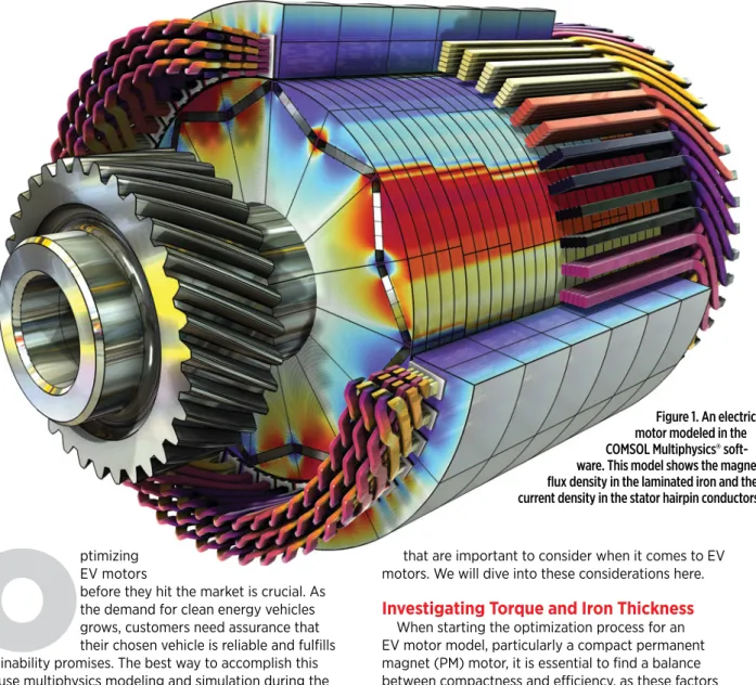
An electric motor modeled in COMSOL Multiphysics® soft-ware. This model shows the magnetic flux density in the laminated iron and the current density in the stator hairpin conductors.
(Image: COMSOL)
FEATURES
12 BorgWarner Targets More- Sustainable E-motors
16 Managing the Evolution of the EV Charging Standard
12 Modeling Considerations for Optimizing EV Motors
18 Sensing to Solve EV Thermal Challenges
20 Betting Big on LFP Battery Cells for Electric CVs
22 Developing EV Batteries with Second Life Use in Mind
24 The Road to Net-Zero EV
Development Labs
ELECTRIC VEHICLES SPECIAL REPORT 2 JANUARY 2024
FROM LEFT: SAE/RYAN GEHM; BORGWARNER
BORGWARNER
A
ll components of an electric propulsion system — the motor, battery pack and inverter, in particular — are interrelated and optimized for a system function.Still, there are significant trade-offs in cost and what’s best for sustainability when developing today’s e-drive systems, according to David Fulton, director of rotating electric machines, PowerDrive Systems at BorgWarner Inc.
“The dominant design for motors today is probably the worst for sustainability in terms of KPIs [key performance indicators] as well as highest in cost.
But it serves the greater good of the system [by enabling] the lowest cost for the battery pack and inverter,” Fulton said at the 2023 SAE COMVEC conference, during his presentation on next-gen motor technology for commercial vehicles.
The majority of current motors are rare-earth- magnet types on the rotor side, he said. These designs use heavy rare earth (HRE) elements that allow them to be used at high temperatures without demagnetizing. “This is a concern because of how short the supply is globally for these, and they virtually all are found in China or near China,”
Fulton said. “This is going to be a short-term supply problem very soon. So, heavy rare earths are going to be the first to be taken off the table.”
Dysprosium and terbium are two HREs commonly used as additives in neodymium
System optimization and lifecycle analysis are key to taking heavy rare earths out of next-gen motors for commercial EVs.
by Ryan Gehm
BorgWarner targets more-sustainable
E-MOTORS
(Nd) magnets. Though light rare earths such as Nd are more plentiful than lead, for example, higher BEV volumes and increased wind power — not to mention unpredictable shifts in geopolitics — likely will drive prices higher, Fulton said.
“Rare earths in general are well known to have high environmental impacts,” he said. “They might be only 3% of the mass fraction of the motor but over 20% on the carbon footprint, because of all that has to happen to process those materials.” The recyclability of rare earth metals also poses a challenge — it’s difficult and not particularly cost-effective.
“People would rather dig them out the ground and make more new magnets than recycle,” Fulton said. “If we did something like grade-to-grade recycling — as we separate plastics into categories and recycle those — and just change the dimensions of the magnet in the future but not what they’re made of, that could help enormously. But the problem with that, of course, is at end-of-life for these motors, is that magnet grade going to be competitive?
My hope is that we find entirely different magnets altogether that are much lower cost to recycle by that point in time.”
Rotor development for next-gen motors
Different types of rotors that are more sustainable have been gaining traction in the automotive industry. Copper induction rotors offer higher conductivity and greater efficiency than aluminum
BorgWarner’s 800-volt HVH320 electric motor for commercial vehicles features rare-earth magnet and aluminum induction rotors.
ELECTRIC VEHICLES SPECIAL REPORT JANUARY 2024 3
FROM LEFT: SAE/RYAN GEHM; BORGWARNER
BORGWARNER
induction, according to Fulton. Wound rotors essentially replace the magnets with electromagnets. “That means we have to provide current to the rotor and need a special excitation board in the inverter to do that,” Fulton explained. “That’s not a problem.”
Another option is non-HRE rotors.
Several automotive OEMs have moved
in this direction. Fulton referenced General Motors and its Chevy Volt hybrid, which uses ferrite magnets, as one example. But there’s a catch with these higher-sustainability solutions: higher system costs.
“Smart engineering” — a term repeatedly used at the SAE COMVEC conference — is necessary to find cost-neutral solutions that satisfy performance and sustainability goals.
System optimization tools and lifecycle analysis will be key to evaluating the relevant metrics and managing trade- offs, according to Fulton. “Having the right kind of toolset to be able to not only [determine] multiphysics optimization, which we’ve done for years, but also to look at cost models and lifecycle analysis for each of these components to weigh that all out is important,” he said.
Material standardization can help with costs as well. “But it’s only relevant in areas where materials are relatively mature,” Fulton said. “I think
“The dominant design for motors today is probably the worst for sustainability in terms of KPIs as well as highest in cost.
But it serves the greater good of the system.”
BorgWarner’s current motors for commercial vehicles offer up to 97% peak efficiency, but development of new rotor technology is ongoing.
David Fulton, director of electric machine innovation at BorgWarner.
rare earth magnets are probably in that camp. Batteries, not so much.”
An alternative, less-than-ideal approach to smart engineering is
“brute force adaptation,” Fulton said, comparing a baseline HRE magnet used in one of BorgWarner’s commercial- vehicle motors to a redesigned zero-HRE magnet. “This [baseline] is very lean on the use of heavy rare earths — as lean as you can get today using the diffusion processes. If we used the best possible non-heavy rare earth magnet for sustainability reasons, we’re redesigning it to get the same function — the same performance, same maximum speed rating and same protection against demagnetization,” Fulton explained.
“But when we do this, we’re handicapped right from the beginning by losing half the coercivity of this magnet material at high temperature.
As a result, to protect the magnet against demagnetization you see how much thicker it becomes [see graphic on next page], and that’s the outcome
ELECTRIC VEHICLES SPECIAL REPORT 4 JANUARY 2024
BOTH IMAGES: BORGWARNER
of brute force adaptation,”
he said. “So even though the cost-per-kilogram is lower, the cost of the magnet is quite a bit higher, over 50% higher. And the magnet is, of course, a significant fraction of the bill-of-material cost of these permanent magnet motors.”
Fulton said engineers can take a step back and employ the five-whys technique to determine new solutions. “Why does the magnet have to tolerate such high temperatures?
Why can’t we deal with something that is not so
high temperature? Of course, that begs the question of the cost of the cooling system. So, there are other ways to look at this that helps us to be more creative and not adapt with a brute-force mentality.”
Engineers also must address the need for shorter charge times and the impact that has on motors. “For instance, 1200-volt [batteries] is something that’s been
looked at; I’ve heard some of our heavy-duty customers talking about it as a way to get to faster charge times,” Fulton said. “But this is going to drive the need for thicker insulation materials in our motors.
Because of creepage and clearance, it has a power-density penalty.
When you have more insulation, you have less room for copper — as a result, your losses go up in the motor. For the same range, that’s going to have a slight battery-size penalty associated with it.”
Motor redesign for zero heavy rare earths should employ a “smart engineering” approach rather than
“brute force adaptation.”
“We know of different higher-sustainability solutions today, but they have system-cost penalties.
They even have sustainability penalties in some cases, by making the motor more sustainable at the expense of the battery being larger.”
- David Fulton, BorgWarnerBorgWarner targets more-sustainable
E-MOTORS
Trade-offs must be managed for next-gen motors that feature more-sustainable rotors.
BOTH IMAGES: BORGWARNER
SR Intertek Ad 0619.qxp_Layout 1 6/5/19 1:29 PM Page 1
TESLA
S
AE International announced in late June 2023 that it intended to standardize the Tesla-developed North American Charging Standard (NACS) EV charging connector for North America. SAE then created the J3400 NACS Task Force to expedite creation of the J3400 NACS Electric Vehicle Coupler standard.Grayson Brulte, host of SAE’s Tomorrow Today podcast, subsequently interviewed Christian Thiele, Director, Global Ground Vehicle Standards, SAE International, and Dr. Rodney McGee, Ph.D., P.E. Chairman, SAE J3400 NACS Task Force and Chief Engineer at the University of Delaware, regarding the work of the J3400 Task Force and other aspects of standardization as electrification technology proliferates throughout the light- and heavy-duty vehicle sectors.
This Q&A is an abbreviated portion of that interview.
Startup EV developer Rivian announced in June 2023 that it intended to adopt the NACS charging standard.
Managing the Evolution of the EV Charging
Standard
Dr. Rodney McGee, Ph.D., P.E. Chairman, SAE J3400 NACS Task Force and Chief Engineer at the University of Delaware.
Christian Thiele, Director, Global Ground Vehicle Standards, SAE International.
How and why SAE International’s standards experts are fast-tracking the adoption of the NACS charging connector for North America as they consider the future of EV-related standards.
CLOCKWISE FROM TOP: RIVIAN; SAE; UNIVERSITY OF DELAWARE
ELECTRIC VEHICLES SPECIAL REPORT 6 JANUARY 2024
TESLA
ELECTRIC VEHICLES SPECIAL REPORT JANUARY 2024 7
Grayson Brulte: You’re going to standardize NACS. What does that process look like? How will you take what Tesla built with the NACS and standardize it for across the industry for use?
Dr. Rodney McGee: Typically, a lot of standards start off at the very conceptual stage where experts basically say, how do we want this to work? And so you literally start with a blank piece of paper and then you get some proposals and then, in, you basically, coalesce on a single sort of solution. That process typically takes some time because, you’re creating something where there was nothing before — or there were things before, but they were different, had different requirements.
The NACS standardization process is a bit different: Today that connector represents both a majority of use in full EV and also a [large] market share in charging stations, especially DC [fast]-charging stations. So, what we’re going be doing in the standards is really capturing the existing mechanical connector to make sure that when other manufacturers want to be interoperable with it, they have a standard to follow that will ensure that things work well.
Brulte: The J3400 Standard covers only the connector, not other aspects of the charging process?
Christian Thiele: The J3400 is just focused on the charger unit — the fixture itself. We have other standards that are working for the interoperability point of view, the communication point of view. The standards back in the day were always focused just on the vehicle; the vehicle was a standalone entity. Now there are communication protocols that are happening with the vehicle, with the people, with infrastructure, with other places.
Brulte: Are there other challenges that you’re going to have to overcome to standardize the NACS connector?
McGee: [Adopting the] NACS does mean people have to make changes, even if it’s just at the mechanical level.
There are electrical differences between NACS and J1772 that will require manufacturers to make changes.
And if, it was a different situation and Tesla hadn’t already had a lot of [charging equipment] in the field, I think there would be a lot of pressure — maybe it would be more open-ended. What exactly would be
the standard? But in this case, most of the people who have joined up with Tesla and their charging system very much want to take advantage of the existing infrastructure.
When you want to take advantage of the existing infrastructure, it
‘bounds’ the work. One of my challenges is to remind people of that — this is a deployed system.
Looking forward, certainly, there are going be things that’ll be added to it within the standards-development process, but just reminding people that nobody wants to adopt or build a NACS standard that’s incompatible with the existing deployment of NACS charging stations.
That’s part of the big reason to move [to the NACS standard]. A lot of people involved with standards are very much used to starting with that blank piece of paper; it helps mitigate those challenges of people wanting to reinvent the wheel, so to speak.
Brulte: The standard for the NACS connector is going to go faster than your “traditional” standards process.
How is that going to be achieved?
McGee: I think Tesla realized they needed to have a standard that was Comparison of Tesla’s North American Charging Standard (NACS) EV charging connector (in black) and SAE J1772 Combined Charging System (CCS) in grey.
CLOCKWISE FROM TOP: RIVIAN; SAE; UNIVERSITY OF DELAWARE
DTNA
ELECTRIC VEHICLES SPECIAL REPORT 8 JANUARY 2024
published by an organization — we use the term SDO, Standards Development Organization. They looked at the options in front of them. The two [SDOs] that would cover this kind of area are the IEC (International Electrotechnical Commission) and SAE.
Some of the international standards can take quite some time. This is due to the way that they’re essentially through national committees. In SAE, the standards are developed by individual experts from a variety both internationally from different suppliers, different automakers, general interests, and there’s a much shorter process to take into account revisions.
The second thing is the fact that NACS is unique in that it already exists in large numbers in the real world. And we’re not starting from a blank piece of
paper. The SAE process can, when there is consensus on what we’re doing — and in this case, there is, because it’s already out there, especially when we talk about the mechanical coupler — move much quicker than would be typical.
Brulte: What is that timeline for the standard? Has SAE or the committee made a public statement around a timeline?
Thiele: We’re looking at publishing something inside of about six months and it’ll be a technical information report. Ideally a standard usually is developed anywhere from 16 to 18 months as typical timeframe. We have been as quick as 10 to 11 months and this will fall around the 11-month window.
Brulte: What happens, Christian, to the J1772 standard? Does that continue to live on? Does it live in other markets or where does that go?
Thiele: Oh yeah. It will continue to live on. There are many vehicles that are out there — obviously [using] the J1772 standard. So that will continue to live on and evolve depending on who adopts the next standard. Europe, we don’t know yet if they’re going to adopt [NACS] in Asia, we don’t know what’s going to happen in emerging markets south America. Africa, we won’t even go there yet because we’re still focused on certain levels of ICE and things of that nature; [vehicle electrification] is going to go into the future just based on infrastructure alone.
But ultimately the focus here should be to see what we can continue to do
Battery Standards
Working with Portland General Electric, Daimler Trucks North America (DTNA) in 2021 opened the ‘Electric Island’ site with eight charging stations suitable for electric cars, buses, box vans, and semi-trucks. Such stations could accommodate the CharIN Megawatt Charging System (MCS) standard, which complies with the SAE J1772-based combined charging system (CCS), and is focused on Class 6-8 commercial vehicles with large battery and packs and the ability to accept a >1 MW charge rate.
DTNA
DURALCO™4700 Ultra Hi-Temp Epoxy to 600ºF Epoxy seals and protects electrical feed-thrus against moisture to 600ºF.
Excellent adhesion to metal, ceramics, glass and plastic.
CORP.
COTRONICS
High Temperature Products Since 1971131 47th Street Brooklyn, NY 11232 www.cotronics.com sales@cotronics.com Tel:866.592.1201 QUALITY PRODUCTS I CUSTOM FORMULATIONS I ISO 9001:2015 CERTIFIED
RESBOND™905 High Temp Low Expansion Adhesive
to 2500ºF DURALCO™125
Flexible Conductive Silver Based Epoxy
to 450ºF
DURALCO™4700 Ultimate Hi-Temp Epoxy Seals And Protects to 600ºF
HIGH TEMPERATURE MATERIALS
FOR ELECTRICAL | STRUCTURAL | INDUSTRIAL
APPLICATIONS TO 4000ºF
ISO 9001: 2015 CERTIFIED
For over 50 years, Cotronics’ highly skilled staff have provided the aerospace, automotive, nuclear, semi-conductor, instrumentation, appliance, chemical processing industries with su- perior, high quality, high temperature products, temperature solutions, specially formulated to meet the demanding specifications that today’s technology requires.
Speak to our Specialists on Adhesives and Materials.
CORP.
COTRONICS
High temperature adhesives and materials for Electrical, Structural, and Industrial applications for use to 4000ºF.
Cotronics offer high temperature solutions to satisfy the most difficult electrical, struc- tural, industrial and medical applications with our proven brand name products:
Durabond™ (Maintenance and Repair Products), Duralco™ (High Temperature
Epoxies), Resbond™ (High Temperature Ceramic Adhesives), Rescor™ (Castable and Machinable Ceramics), Thermeez™
(Insulation Products), and High Purity Materials.
Cotronics is ISO 9001:2015 certified.
You have challenging applications…
we have solutions.
For over 50 years, Cotronics’ highly skilled staff of researchers, engineers, chemists, technicians and sales assistants have pro- vided the automotive, aerospace, nuclear, appliance, semi-conductor, instrumenta- tion, chemical processing industries a reli- able source of superior quality, high temperature products specially formulated to meet the demanding specifications that today’s technology requires. Cotronics is ISO 9001:2015 certified and provides the utmost in excellence. Call 718-788-5533 or email: [email protected] for Cotronics’
application engineers for specific technical information, adhesive suggestions and custom solutions; Cotronics’ customer service department for price quotes and placing orders for high temperature stock materials.
www.cotronics.com
Company Description
Products/Services Offered Cotronics Corporation
131 47th Street Brooklyn, NY 11232 Phone: 866-592-1201 sales@cotronics.com www.cotronics.com
DURAPOT™ 4460 Resists Electricity, Chemicals and Mois-
ture to 600ºF SAE_Jan2024_Island_Wrap_Layout 1 1/4/24 6:59 PM Page 4
Products/Services Offered About Our Company
U.S. DOT/ADOBE STOCK
ELECTRIC VEHICLES SPECIAL REPORT 10 JANUARY 2024
and develop. We continue to focus on the J1772 to deliver the best standard for that particular application. And even in the J3400 [NACS standard], I think we will be referencing the J1772 document because of some of the intricacies that are there from a communication protocol, etc. and technical statements that are in there just so we don’t repeat ourselves.
McGee: It’s important to remember that J1772 is also used in Japan and South Korea. There’s no indication at the moment that’s changing.
There are a number of other smaller countries that may continue to use that plug and even if over time the plug becomes more common, it’s a lot of the descriptions of things that live in J1772 that may continue to be described within that document.
Brulte: What is the impact of NACS on commercial vehicles, say Class 6 through Class 8?
McGee: SAE has Ground Vehicle standards and under that are the Truck and Bus Council and the Motor Vehicle Council. The NACS Task force lives under Motor Vehicle Council. I also have standards that I work on in Truck and Bus.
One of the things that come out of this discussion is a good analogy: if you’ve ever gone to one of those stations that service tractor-trailer [Class 8] trucks, you know that they have bigger filling nozzles because those vehicles need quicker energy delivery, via diesel in those cases.
They [commercial-vehicle interests]
want higher-power DC charging, that’s megawatt. SAE has a megawatt-level DC charging standard, focused on those vehicles for plugin charging. A couple of years ago, SAE published overhead- charging non-handheld couplers, and the J3105 series, which is basically about electrifying city buses and vehicles like this. For DC charging, [generally] we want higher power levels than the passenger- car market, because we have batteries that are three and four times bigger.
Those vehicles may have goods, sometimes millions of dollars’ worth of goods on them. They can’t fail.
They need to get to their destination.
That is one of the legitimate reasons that those vehicles generally lag behind passenger-car [change and innovation], because the truck sector wants [equipment] that’s known reliable and that’s well-understood.
Even though there’s been some high-profile deployments of vehicles like electric school buses, they’re really leveraging passenger-car standards. A city bus, we pretty much drive these buses 23 hours a day, so we need overhead charging at above a megawatt.
It’s really about the truck and bus [interests] deciding to electrify and then figuring out how they get there from here and making standards that sort of enable the mass deployment.
To listen to the full episode of the podcast, visit https://
tinyurl.com/yckefu9e.
Overhead charging of commercial vehicles is one option to address those vehicles’ higher- power charging needs and SAE has standards development for this charging modality.
Battery Standards
U.S. DOT/ADOBE STOCK
+1 781-897-1710 | [email protected]
pickeringrelay.com
Reed Relays
for EV & Charge Point Testing
With very low leakage currents (less than 1 nA) and very high stand-off voltages achievable in a small package, reed relays are the logical choice for EV testing applications where safety is a priority.
For a free working sample go to: pickeringrelay.com/samples
yFrom 1 kV to 7.5 kV switching
y
Minimum standoff between 1.5 kV to 10 kV
yFrom 10 W to 200 W switching power
yOptional electrostatic screen
y
Typically, 10
9operations life expectancy
y
Available in through-hole SIL and SMD packages
y
Many build options available to suit a variety of applications
1968 - 2023
5
Pickering5
Years100%
TestedLongevity Longevity
Stocked by
SCAN ME
BOTH IMAGES: COMSOL
COMSOL
ELECTRIC VEHICLES SPECIAL REPORT 12 JANUARY 2024
Modeling Considerations for Optimizing EV Motors
Certain aspects of electric vehicle (EV) motors need to be carefully investigated and optimized, such as the torque and temperature rise. The most effective way to perform such analysis and optimization is by using multiphysics modeling and simulation.
O
ptimizing EV motors before they hit the market is crucial. As the demand for clean energy vehicles grows, customers need assurance that their chosen vehicle is reliable and fulfills sustainability promises. The best way to accomplish this is to use multiphysics modeling and simulation during the optimization process (Figure 1). For the engineer working on the optimization, there are several modeling aspectsthat are important to consider when it comes to EV motors. We will dive into these considerations here.
Investigating Torque and Iron Thickness
When starting the optimization process for an EV motor model, particularly a compact permanent magnet (PM) motor, it is essential to find a balance between compactness and efficiency, as these factors conflict. Achieving efficiency goals while limiting the size of machine components is challenging.
Figure 1. An electric motor modeled in the COMSOL Multiphysics® soft- ware. This model shows the magnetic flux density in the laminated iron and the current density in the stator hairpin conductors.
BOTH IMAGES: COMSOL
COMSOL
ELECTRIC VEHICLES SPECIAL REPORT JANUARY 2024 13
Efficiency equates to less energy consumption, and finding a way to limit this involves examining the motors’
current loading, which represents the amount of current applied to the stator winding. In a PM motor, the magnetic fields generated by the rotor magnets and the stator current rotate in synchronization. The interaction between these magnetic fields generates the net torque that converts the stator winding currents into mechanical power. A maximum amount of mechanical torque needs to be exerted on the rotor so that it will rotate with as much force as the engineer wants, and in the direction they want. All of this considered, the engineer will want to determine whether the current loading is maintainable or too high, as having a too-high current loading will cause the core material to go into heavy saturation, which will result in a decline of mechanical power.
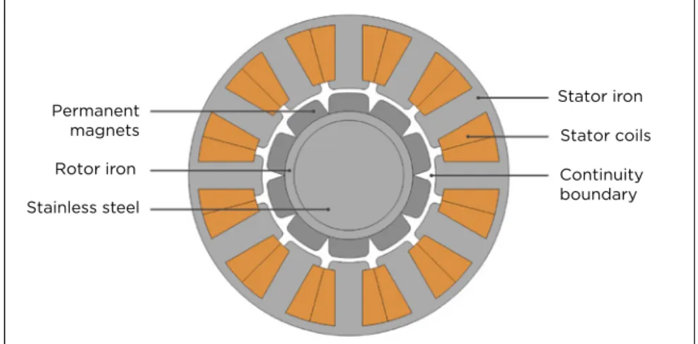
The best way to examine the current loading and torque is by testing the model setup. To better visualize the topics discussed here, consider a 10-pole PM machine with 12 slots (Figure 2).
Because the torque relies on the synchronization of the magnetic fields produced by the rotor and the stator, the optimum angle offset between the rotor and stator fields must be determined.
The offset angle can be found by either rotating the rotor with an angular span corresponding to an electrical period or by cycling the stator current through an electrical period, with the rotor at rest.
Once the optimum angle offset is determined, the engineer can begin investigating ways to improve efficiency and save material use. There are of course many ways one can do this, but here, we will discuss one method:
examining the dependency between the stator iron material, current loading, and torque output. This can be found by analyzing the thickness of the iron core and its impact on efficiency.
The engineer should simulate different variants of iron thickness, focusing on the effects that each level of thickness has on the rotor torque.
By doing this, an iron thickness value
that maintains optimal torque and stays within size (compactness), weight, and pricing restrictions or goals can be determined.
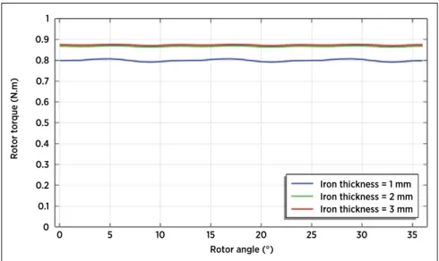
For the example motor seen in Figure 2, it is found that the optimal iron thickness is 2 mm; using a thickness under this value will negatively impact the torque. For example, as seen in Figure 3, a thickness of 1 mm resulted in lower torque. Going thicker than 2 mm, however, is not the optimal solution, as it requires an increase in material and therefore increases in weight and cost without a substantial increase in torque.
Determining Losses, Temperature Rise, and Cooling Solutions
Once the optimal iron thickness is determined, it is time to calculate the iron and copper losses. An increase in speed (and the consequent losses)
can make it difficult to keep a motor cool, which will cause a motor to reach its thermal limit. When this spike in motor temperature occurs, the motor flux density can decrease, having a domino effect on the torque and overall efficiency. For these reasons, one should look at iron and copper losses first, and then at temperature rise and cooling solutions.
Iron losses occur due to time- varying magnetic flux density and they include hysteresis and eddy current losses. Copper losses, on the other hand, happen because of conduction current flow, and they include ohmic losses within the stator coil. Both types of losses can be calculated in the COMSOL Multiphysics® software.
The software offers a built-in feature for loss calculation as well as features for creating plots of the losses and Permanent
magnets Rotor iron Stainless steel
Stator iron Stator coils Continuity boundary
1 0.9 0.8 0.7 0.6 0.5 0.4 0.3 0.2 0.1
0 0 5 10 15 20 25 30 35
Rotor angle (°)
Iron thickness = 1 mm Iron thickness = 2 mm Iron thickness = 3 mm
Rotor torque (N.m)
Figure 2. Example model of a 10-pole PM motor with 12 slots.
Figure 3. A plot showing variations of the example motor’s rotor torque and iron thickness.
BOTH IMAGES: COMSOL
ELECTRIC VEHICLES SPECIAL REPORT 14 JANUARY 2024
Battery Modeling
their important characteristics, such as how they vary as functions of both speed and current amplitude.
From there, it is useful to compute the losses in combination with heat transfer phenomena using simulation software. This makes it possible to visualize how much the motor will
rise in temperature and how different forms of cooling, such as forced or natural air convection or forced water cooling, can help subdue it. Obtaining a visualization of these conditions will help in determining the needed insulation class. For example, assume that for the model shown here, forced
air convection is the preferred method.
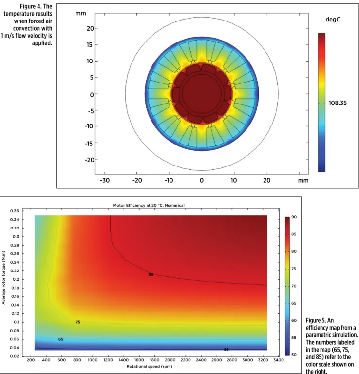
When forced convection with 1 m/s flow velocity is applied to the model, the results indicate that the most beneficial insulation class in this case would be 130 (B), which means that 130 °C would be the maximum hot spot temperature for the design (Figure 4).
200 0.36 0.34 0.32 0.3
55 65
75
85 0.28
0.26 0.24 0.22 0.2 0.18 0.16 0.14 0.12 0.1 0.08 0.06 0.04
0.02 400 600 800 1000 1200 1400 1600 1800 2000 2200 2400 2600 2800 3000 3200 3400 Rotational speed (rpm)
Motor Efficiency at 20 °C, Numerical
Average rotor torque (N.m)
50 55 60 65 70 75 80 85 90
Figure 5. An efficiency map from a parametric simulation.
The numbers labeled in the map (65, 75, and 85) refer to the color scale shown on the right.
Figure 4. The temperature results when forced air convection with 1 m/s flow velocity is applied.
-30 -20 -10 0 10 20 mm
mm degC
108.35 20
15 10 5 0 -5 -10 -15 -20
For Integrated EV Systems Solutions
Think Curtis
With Curtis on your team, electrification is easy.
- Expertise in electric and hybrid powertrains of any configuration.
- System-level design options in VCL or embedded C-code to solve for your specific needs.
- High-efficiency Motor Controllers (Inverters) for e-traction, e-pump or hybrid on-engine generator control covering most system voltages.
- Powerful, highly customizable HMI displays purpose-built for demanding off-highway applications.
- Dedicated engineering support, delivering solutions that meet with your exact specifications.
www.curtisinstruments.com
BOTH IMAGES: COMSOL
For Integrated EV Systems Solutions
Think Curtis
With Curtis on your team, electrification is easy.
- Expertise in electric and hybrid powertrains of any configuration.
- System-level design options in VCL or embedded C-code to solve for your specific needs.
- High-efficiency Motor Controllers (Inverters) for e-traction, e-pump or hybrid on-engine generator control covering most system voltages.
- Powerful, highly customizable HMI displays purpose-built for demanding off-highway applications.
- Dedicated engineering support, delivering solutions that meet with your exact specifications.
www.curtisinstruments.com
COMSOL
ELECTRIC VEHICLES SPECIAL REPORT 16 JANUARY 2024
Battery Modeling
Analyzing an Efficiency Map
The data collected thus far can be combined and accounted for in an efficiency map (Figure 5), which shows the efficiency as a function of speed and torque. This makes it possible to first estimate the overall energy used by a motor during a complete drive cycle and then to deduce the range of the vehicle after a single charge for a given battery size. Given that an EV motor’s marketability depends on how well it utilizes electrical power, it is safe to say that taking the time to create an efficiency map is worthwhile.
Efficiency maps use color and contour to help visualize the efficiency.
In Figure 5, the blue, yellow, and green regions have low efficiency, and the vehicle altogether consumes less power at the low speed or low torque points as compared to the red region, where both speed and torque are high.
If satisfied with the energy
conservation results that the efficiency map shows, the engineer will have optimized the motor effectively and can begin the next stage of development.
Improving Motor Noise Levels
In addition to optimizing the motor’s functionality and sustainability, a crucial
aspect must be taken into account:
motor acoustics. EVs are significantly quieter than their conventional counterparts, which initially raised safety concerns due to the difficulty in alerting nearby cyclists and pedestrians.
As a result, it has become standard practice for EV designers to incorporate a warning sound. Multiphysics modeling and simulation can be used to manage this sound as well as the overall acoustics of the vehicle, enabling engineers to ensure that it produces ideal sound before spending time and money to make a prototype.
To determine the acoustic
behavior, there are three analyses the engineer should perform. First up is a transient analysis to determine the electromagnetic forces in the time domain for a given rotation speed. A time-dependent analysis is needed for electric machines since time-harmonic analyses do not account for motion.
Next, the Fourier transform can be used to convert the time-domain forces into frequency-domain harmonics. This allows for an efficient computation of the vibrations and noise emitted from motor housing.
The third step is to perform a vibroacoustic analysis of each
harmonic at different speeds of rotation. These harmonics can be plotted using a Campbell diagram (Figure 6), which shows loudness as a function of speed and frequency for a set of harmonics. With this, the engineer can find the frequency and intensity of the emitted noise (also known as the sound pressure level).
With COMSOL Multiphysics, the engineer can export the noise plots to WAV files and hear how the motor will sound. Depending on the results, they can make any adjustments they wish to the rotor slot sizes, position, and shapes until the motor produces ideal noise.
The optimization of an EV motor involves a careful examination of numerous factors, such as torque, iron thickness, and temperature rise.
Multiphysics modeling and simulation make it easy for engineers to see how the different physics phenomena within an electric motor interact and optimize their design accordingly.
COMSOL Multiphysics is a registered trademark of COMSOL AB.
This article was written by Beth Beaudry of COMSOL (Burlington, MA). For more information, visit www.comsol.com.
1000 4000
3500
55 3000
2500
2000
1500
1000
500
0
2000 3000 4000 5000 6000 7000 8000 9000 10000
-65.5 Revolutions (RPM)
Campbell Diagram, First Microphone
Frequency (Hz)
30 35 40 45 50 55 60 56.9
Figure 6. A Campbell diagram for analyzing motor frequency. This plot focuses on a given microphone position.
Each line represents a harmonic, and on the color scale, red represents louder noise.
COMSOL
The trusted technology partner for manufacturing mission-critical PCBs.
Summit Interconnect is the largest, privately held PCB manufacturer in North America offering a broad range of highly reliable, advanced technology PCBs. With eight high-tech facilities and thousands of employees, we work alongside customers to push the boundaries of what is possible, helping to create inventive and transformative electronic products.
Summit Interconnect proudly serves these high-growth markets:
Aerospace & Defense
Automotive Consumer Electronics
Semiconductor
Computing & Datacom Space
Industrial Medical
Rigid. Flex. Rigid-Flex. HDI. RF. Assembly.
A Total PCB Solution from
a Single Manufacturing Partner
ELECTRIC VEHICLES SPECIAL REPORT 18 JANUARY 2024
ALL IMAGES: TDK-MICRONAS
TDK-MICRONAS
A
common criticism of electric vehicles (EVs) is that extremes of heat and cold adversely affect their performance, particularly range. OEMs have been aware of the issue and have innovated and iterated technologies to solve it.EVs increasingly are being engineered with sophisticated heating, cooling and ventilation (HVAC) systems based on some of the most advanced and robust sensors and actuators available.
These systems mitigate against the effects of thermal extremes that, admittedly, still challenge IC-engine vehicles on an infrequent basis. But there are tradeoffs. The ICE vehicle’s HVAC is a relatively simple affair involving air cooling, a coolant (water ethylene glycol, or WEG), heaters, and heat exchangers (including air conditioners). HVAC systems for EVs by necessity are far more complex. Understanding the details is important to designing an effective system.
EV HVAC differences
An EV HVAC system has multiple temperature-sensitive subsystems and components, all with different optimal temperature ranges that only sometimes overlap. Specifically:
• Magnetic elements in the motor must be kept below 80° C (176° F) to keep them from demagnetizing.
• Motor inverter and charging electronics must be kept at less than 120° C (248° F)
• Lithium-ion batteries must operate between 10° C and 40° C (50° F and 104° F).
The complexities of electric-vehicle HVAC require new sensing solutions.
An expert at TDK explains.
by Jeroen Van Ham
Sensing to solve EV thermal challenges
• A hydrogen fuel cell may need to run somewhere between 100° C and 200° C (212° F and 392° F, depending on the fuel-cell stack technology)
• Passengers in any vehicle tend to be most comfortable within a few degrees of 20° C (68° F).
EV HVAC complexity derives from having to satisfy all requirements, often simultaneously. The complexity begins with the three distinct heating/cooling loops that are part of every EV. The battery system, power system and the passenger space each have a dedicated loop.
Handling so many systems that operate in different temperature ranges requires careful management.
For example, EV manufacturers had to devise a means of handling both power electronics (operable to 120° C) and the batteries (operable to 40° C).
EV engineers divide what would have been a single thermal loop covering both the power electronics and the battery into two channels to take advantage of the existence of the vehicle’s air-conditioning unit.
In one channel of the thermal loop, WEG cycles through power electronics and radiator at some temperature between 40° C and 100° C, while in the other channel of the loop, the WEG is chilled below 40° C by an air-conditioning system. This is done with a chiller that transfers the heat from the battery loop WEG to the air-conditioning refrigerant.
The complex HVAC required by EVs depends on leading-edge sensors, actuators, and controllers to assure that the vehicles operate at peak performance in all ambient thermal conditions.
ELECTRIC VEHICLES SPECIAL REPORT JANUARY 2024 19
ALL IMAGES: TDK-MICRONAS
TDK-MICRONAS
Regulating EV battery temp
An EV battery can have thousands of battery cells. Each cell has to be individually monitored for temperature and voltage. Voltage sensing is necessary in large part because batteries operate better when the load across all the constituent cells is balanced as evenly as possible. This data is fed into each EV’s battery management system (BMS).
For temperature sensing, in hot weather the battery needs to be cooled to avoid battery degradation that begins to accelerate at higher than 40° C. That involves using coolants, as described above, as well as vents and fans.
During cold weather, the battery needs to be heated. When Li-ion batteries get too cold, range is compromised. Note, too, that the battery must be kept warm even when the vehicle is not being driven. This is why EV makers have been equipping batteries with dedicated heaters.
Keeping the batteries in the optimal temperature range has to be done anyway and it helps maintain range when the weather grows cold – a feature that EV critics frequently miss.
Sensor rich
The process of heating and cooling the multiple EV subsystems so that they remain in their optimal temperature ranges involves more heat pumps, water pumps,
three-way valves, expansion valves and other equipment than found in ICE vehicles. All of these elements must be monitored and controlled.
This requires temperature sensors, pressure- temperature sensors mounted in various positions and pressure sensors for the WEG refrigerant.
Many of these sensors need protection from the elements and so must be mounted in appropriate packaging. They all need to be positioned and attached with care, with an awareness that motor vehicles are perpetually subject to shock and vibration on the road. TDK, for example, provides many of the required actuators (HVC 4xyzF) and sensors (HAL 39xy) to extract the maximum range from a battery at all times.
Effective EV HVAC = safety
Precise measurement is necessary not just for the efficient operation of the vehicle. It is also an issue of safety.
Most EVs will rely at least partially on taking an AC source as an input and converting this into DC to charge the battery. The amount of power through both AC and DC charge points often is in excess of 100 kW.
Generating heat as a by-product is inevitable. If not managed, the accumulated heat could become a potential safety hazard.
That makes temperature sensing even more important at all critical points throughout the EV power system.
The IEC demands that charging plugs include a
temperature sensor to ensure safe operation. TDK supplies high-voltage-resistant negative temperature coefficient (NTC) sensors in these hotspots, as they feature a high operating temperature and high electrical insulation.
The complex HVAC required by EVs depends on leading-edge sensors, actuators and controllers to assure that the vehicles operate at peak performance — including when it’s cold outside.
Dr. Jeroen Van Ham oversees the sensor-systems portfolio at TDK.
HVAC cool-weather cycle.
EV heat-pump function showing related sensors.
ELECTRIC VEHICLES SPECIAL REPORT 20 JANUARY 2024
CLOCKWISE FROM TOP LEFT: EVE ENERGY; PACCAR; BLUE BIRD; FORD
DAIMLER TRUCK
C
hina remains the clear leader in manufacturing of lithium-ion battery cells for commercial vehicles and passenger cars, but North America will claim some of that share in the coming years as it becomes the fastest- growing regional market for planned cell capacity, according to a recent report from Clean Energy Associates (CEA).As global lithium-ion battery-cell capacity is set to increase by 186% from 2022 to 2025, North America’s capacity growth is expected to outpace Europe’s, according to CEA, primarily due to incentives in the U.S.’s Inflation Reduction Act (IRA).
A similarly optimistic outlook from the Department of Energy’s (DOE) Vehicle Technologies Office shows that total battery manufacturing capacity in North America is projected to be nearly 20 times greater in 2030 compared to 2021 — about 1,000 gigawatt-hours (GWh) per year vs. 55 GWh/year.
Automakers such as Ford (www.sae.org/news/2022/07/
ford-battery-materials-security) previously announced plans to install lithium iron phosphate (LFP) cell production capacity in North America. Commercial-vehicle manufacturers similarly are driving growth in this area, evidenced by a major announcement on Sept. 6 that Accelera by Cummins, Daimler Truck and Paccar are forming a joint venture to manufacture LFP battery cells for battery-electric commercial vehicles and industrial applications.
LFP ‘excellent’ for CVs
Total investment is expected to be about $2-3 billion for the 21-GWh, “state-of-the-art” dedicated LFP cell factory. The first battery cells will be produced for vehicles in North America, with production scheduled to start in 2027, a Daimler Truck spokesperson shared with Truck & Off-Highway Engineering.
Accelera by Cummins — the company’s zero-emissions business unit — Daimler Truck and Paccar each will own 30% of the joint venture. Chinese cell maker EVE Energy will serve as the technology partner and hold a 10% ownership stake. EVE Energy will contribute its LFP battery-cell design and manufacturing expertise.
Accelera by Cummins, Daimler Truck and Paccar collaborate to establish a 21-GWh dedicated factory in the U.S. with technology partner EVE Energy.
by Ryan Gehm
Betting big on LFP battery cells for
ELECTRIC CV s
“Twenty-one gigawatt-hour is a very big number in the context of trucks and buses,” Jamie Fox, principal analyst at Interact Analysis, commented on the announcement. “A 21-GWh plant, operating at full capacity in 2026, would provide enough batteries for the entire North American market for all battery-electric buses and medium- and heavy-duty trucks combined, assuming about 10% of trucks are electric in that year.”
The partners said that the joint venture initially will focus on LFP battery cells because they offer several advantages compared to other battery chemistries such as NMC (nickel manganese cobalt) lithium-ion technology. The lower cost of LFP — largely because iron is more abundant than nickel and cobalt — is a major factor, as is its longer life and enhanced safety because LFP cells are less prone to combustion and thermal runaway.
“Based on today’s outlook, LFP is an excellent choice for commercial vehicles,” the Daimler Truck spokesperson said. “Various metrics or KPIs are considered in the development and design of the cell chemistry, and LFP has several advantages in terms of lifetime, cost and thermal spread resistance.”
Achieving economies of scale
The partners are collaborating to find the optimal location for the battery-cell production facility.
“The team has narrowed down the list of states and locations to a few that meet our requirements, avoiding sensitive geographic locations due to CFIUS [Committee on Foreign Investment in the United States] considerations, and is now working on the final selection,” the spokesperson said. The final location is expected to be announced within the next six months.
The first battery cells from the joint-venture LFP cell factory will be produced for vehicles in North America, with production scheduled to start in 2027. Freightliner eCascadia is shown.
ELECTRIC VEHICLES SPECIAL REPORT JANUARY 2024 21
CLOCKWISE FROM TOP LEFT: EVE ENERGY; PACCAR; BLUE BIRD; FORD
DAIMLER TRUCK
The strategic JV enables the companies to create the necessary scale to meet the expected growing demand for battery technology throughout this decade, according to Daimler Truck CEO Martin Daum. “For Daimler Truck, partnerships and a strict focus on costs and smart capital allocation are the key levers to succeed on the path towards sustainable transportation,” he said in a statement. “This planned joint venture enables economies of scale beyond Daimler Truck. It is a key puzzle piece of our battery-industrialization strategy, ensuring access to the right battery-cell technology at the right cost.”
The partners stressed their commitment to reducing carbon emissions consistent with the Paris Climate Agreement. “We have the responsibility to decarbonize in a way that is best for all of our stakeholders and the planet. This requires working closely with key partners,”
Jennifer Rumsey, Cummins chair and CEO, said in the statement. “Not only are we advancing a key technology solution for our customers, but accelerating the energy transition in the United States.”
“Our vision is the highest quality, locally produced battery technology to enhance the operations of our customers and help them achieve their operational and environmental goals,” added Preston Feight, CEO of Paccar.
The transaction is subject to customary closing conditions and receipt of applicable merger control and regulatory approvals.
“Battery packs in trucks and buses can have double the per- kWh price that passenger cars have — this factory may contribute towards developing economies of scale that can reduce this gap,”
Interact Analysis’ Fox said. “Some may want to wait and see until the factory has actually been built, but this announcement is big enough to make people who took a bearish stance on electric trucks in North America to reconsider their position.”
Chinese cell maker EVE Energy will serve as the technology partner and contribute its LFP battery-cell design and manufacturing expertise.
Kenworth and Peterbilt electric trucks will benefit from LFP cell technology that offers advantages in cost, lifetime and thermal
spread resistance.
Ford previously announced its own plans to manufacture LFP cells in the U.S. and offer two battery chemistries for its EVs because of their unique benefits.
Accelera works with Blue Bird to deploy electric school buses in North America, a segment that could benefit from the LFP cells produced by the new venture
“It is a key puzzle piece of our battery-industrialization strategy,
ensuring access to the right battery-cell technology at the right cost.”
- Martin Daum, Daimler Truck CEO
ELECTRIC VEHICLES SPECIAL REPORT 22 JANUARY 2024
Developing EV Batteries
with Second Life Use in Mind
A
s the automotive industry continues to focus on designing and developing electric vehicles (EVs), new challenges and considerations come along for the ride. As the EV market grows, the industry must be prepared for new end-of-life matters, even during the preliminary stages of development. One important piece of this puzzle is the batteries powering EVs, which usually still maintain around 80 percent usable capacity when they are no longer considered suitable for vehicle use.At that time, it may be possible to repurpose the battery for a
“second life” use, such as powering commercial appliances or medical equipment, or for energy storage in buildings utilizing solar panels.
There are multiple factors, challenges, and processes in assessing a battery once it is no longer an option for powering an EV. If the battery can be used for a second life, the process is not as simple or straightforward as it may first seem to be. Preparing the batteries for a second life, often includes transitioning them to a different industry. When original equipment manufacturers (OEMs) are developing EVs and their batteries for their “first life” it is important to keep potential second life uses in mind.
End of First Life
When the battery of an electric vehicle is operating below optimal range for driving, it must be replaced.
Such a determination could stem from customer complaints about vehicle range, scheduled vehicle battery upgrades, repair assessments, general maintenance sessions, or at other times. Once it is deemed unsuitable
for on-road use, manufacturers must decide what to do with the battery: discard it, recycle it, or repurpose it for another use.
Discarding the battery presents challenges in terms of landfill space and usage, as well as how to properly dispose of hazardous chemicals and metals. Many regions have vehicle end-of-life guidelines that require a certain percentage of the car to be re-used or recycled, such as the EU ELV Directive. This regulation requires that 85 percent of vehicle weight be reused or recycled; only 15 percent of the vehicle weight can be discarded.
Batteries can account for up to 10 percent of vehicle’s total weight, making recycling or repurposing a better option under the ELV Directive.
Recycling EV batteries is not always easy since they contain heavy metals and proprietary chemical compounds.
Recycling requires careful handling and can be quite costly. In fact, recycling can prove more expensive than the value of the materials pulled from the battery. Given the challenges behind discarding and recycling EV batteries, repurposing them may be the preferred option for many manufacturers.
Because most electric vehicle batteries are still operating at around an 80 percent capacity level at their end- of-life stage, utilities and manufacturers in other industries are starting to see a used EV battery as a low cost/high quality power source. This unlocks a number of possibilities for a battery’s use, once it is properly assessed to be repurposed, remanufactured, and recertified to applicable industry standards for its new use.
Keeping this process in mind, designers and engineers who are developing EV batteries can help
those at the “second life” stage by considering applicable standards, testing needs and other best practices.
Applicable Standards and Testing Needs
When being repurposed and recertified, EV batteries will need to be transported, and lithium-ion batteries must meet provisions in the UN 38.3 standard to be transported.
To adhere to the basics of UN 38.3, it is important for the EV OEM to maintain copies of all UN 38.3 test reports, including those from subcontractors and suppliers. These summaries need to be available upon request to maintain compliance and should identify samples tested, as well as models/
versions covered by the test report.
If the OEM is repurposing the battery these reports will be needed.
If another party is taking on the reconstruction and recertification, having this information ready will benefit the second life process.
While an “as-is” battery may not require re-testing per UN 38.3, the repurposer is still required to provide evidence of compliance for any shipment, if requested by a competent authority. If a battery is disassembled into component modules or cells, the repurposer would also be required to demonstrate UN 38.3 compliance for any sub-assembly of battery that is subsequently transported. The same is true for any newly created batteries that are assembled from reclaimed cells or modules.
An EV battery repurposer can use UL 1974 to assess whether the batteries qualify for reuse/
repurposing. The standard applies to battery packs, cells, modules, and electrochemical capacitors. It contains
ELECTRIC VEHICLES SPECIAL REPORT JANUARY 2024 23 actions to demonstrate a battery
can be repurposed and moved from one industry to another, as well as an overview of the rework/screening process. Another key component of the standard is guidance to illustrate knowledge of the original battery design. To assist the second life process, OEMs can ensure that this knowledge is understood, sharing any necessary information, data, sketches, testing reports or other means of illustrating this information.
UL 1974 also includes guidance on cell evaluation at the module level (when cells cannot be separated individually) and allows for various usage cases: reuse, repurpose, or remanufacture. The manufacturer can use this to establish the battery’s condition to proceed with further assessments and testing. This often includes application-specific safety certification, such as UL 1973 for stationary storage batteries.
Typically, when a Nationally Recognized Testing Laboratory (NRTL) certifies a product, the original manufacturing process must be audited or assessed periodically. Because a
repurposed battery’s manufacturing has occurred in the past, the NRTL must assess the screening and sorting process, as well as any re- manufacturing, to ensure that only compliant batteries are allowed in the new application. This screening process must include a documented verification that unfit batteries are prevented from re-entering the market.
Initial Manufacturer
Considerations for Second Life
Since the standards and guidelines continue to evolve for EV batteries, it is important to stay informed on new developments and requirements for reuse, including standards around end- of-life stages for batteries, as they will impact the potential outcomes for an EV battery. Stay informed about new or changing standards on transporting batteries, repurposing batteries and general battery safety and compliance, as these will all impact the EV battery in both its first and second lives.
The EV battery is an expensive, heavy piece of equipment. For both those reasons, and because the used battery still offers a great deal
of energy storage potential, recycling and reuse is often a preferred option at the end- of-life stage. As manufacturers seek to find a second life for EV batteries at the end of their initial use, it is important to know not only the options but the process for repurposing a battery for new use.
As second life usage expands, there will be additional regulations or regulatory guidance. Each region or country will adopt or allow re-used or repurposed batteries according to their own lessons learned or local concerns. Therefore, OEMs and repurposers must consider that the regulatory landscape will most likely evolve. That landscape includes legal liability, transportation, application-specific safety, and labeling for any re-purposed battery. Additionally, expect changes in storage, disposal, and recycling requirements for cells and batteries that are not re-purposed.
Clear communication within your organization, with testing and certification bodies and with partners in the second-life industry will also help to ensure a smooth, timely transition, allowing automotive OEMs to meet end-of-life requirements for the battery and the vehicle. OEMs may want to consider designing batteries for easier repurposing, or by considering a specific intended application, so that the original battery already complies with the construction and testing requirements of the second use applications. At minimum, all manufacturers should at least have an awareness of how their batteries may be re-used or repurposed at the end of their original life, and prepare accordingly today.
This article was written by Rich Byczek, Global Director, Intertek (London, U.K). For more information visit, www.intertek.com.
BOTH IMAGES: UNICO
The Road to Net-Zero EV Development Labs
Test systems should be designed in a way to recover the energy locally and utilize the inherent benefit of electric vehicles to share charge and discharge energy on a testbed level.
A
s automotive companies transition their product portfolio to fully electric, the development and validation of the electric powertrain and battery is a key enabler to success. The electric powertrain, which consists of the battery, tractioninverters, and electric motors, or a combination of components like an e-axle, is a primary cost driver, has a tremendous effect on the driver’s user experience, and has the highest risk for expensive recalls and warranty issues. Because of the importance of the electric powertrain, automotive customers must transition their existing development and validation facilities to electric component and system testing which often requires a substantial increase in needed electrical power. However, intelligent installations can use green energy generation, second life energy storage, and high-efficiency test systems to reduce, or even eliminate this challenge.
The demand for power is clear with some basic, back of the napkin, math. If we have battery packs that average 100kWh, and the test profiles must include simulations of repeated DC fast charging (20 percent to 80 percent SOC) with the target recharge of 20 min, which seems to be the desired target time by many consumers, this fast charge event needs to be 80% - 20% = 60% * 100kWh for a DC fast charge capacity of 60kWh. Then, for a 20-min DC Fast Charge we would need (60 min/20 min)*60kWh) or 280kW of power. In addition, a typical validation program would have 20 packs (or more) in continuous test for multiple years, so just for these tests we would need a facility power of 280kW*20 = 5.1MW.
Of course, the matching E-Drive testbeds would have similar requirements confirming that tremendous power is needed to test these electric powertrain components and this power requirement in both directions as electrified powertrains have the enormous benefit of returning energy as well as consuming it. But this bidirectionality doesn’t SERGII CHERNOV/SHUTTERSTOCK.COM
ELECTRIC VEHICLES SPECIAL REPORT 24 JANUARY 2024
BOTH IMAGES: UNICO
ELECTRIC VEHICLES SPECIAL REPORT JANUARY 2024 25
SERGII CHERNOV/SHUTTERSTOCK.COM
help us (on the surface) with our needed power connections.
We can manage this power need with
“lab management” software which can monitor test profiles to predict power consumption in the future and limit some testbeds in case power limits are being reached, but this can often delay testing or cause issues where faults occur and excess energy is needed, or doesn’t have any place to go. To take the solution a step further, we must outfit these test facilities with systems that use the available energy effectively in the first place.
There are several methods for this combining a mix of utilizing green energy like solar and wind to supplement the energy needs, a stationary energy source like second life batteries to store or provide excess energy when needed, and efficient test systems that have high electrical efficiency and can share the energy between testbeds for both AC and DC applications. If done correctly, the net energy effect on the facility can be zero, or in many cases, provide energy back to the facility to support the building.
If we start from the DUT (Device Under Test) and work our way back to the power source, we can start to see how this can easily play out.
Combining Test Systems
If we keep it simple and focus on EV battery and traction motor testing, starting with the battery, we need to provide energy to charge the battery which simulates the real-world condition of a DC fast charge event or regenerative braking during driving. We also need energy for electric motor testing to drive the electric motor which is replicating the electric motor accelerating the car. But we also need to consume energy from the battery to simulate the real-world situation when it is powering the electric motor to accelerate the car or absorb energy from the traction motor during the previously mentioned regenerative braking events.
If we think of this myopically, and only consider one test channel, we will have a building AC grid connection to provide the AC power connection to the Active Front End (AFE). This AFE then converts the AC power to DC and then
DC BUS DC BUS
GRID
Common DC Bus
400VDC
800VDC Battery Energy Storage Systems
1200VDC 800VDC
DRIVEAC AC
DRIVE AC
DRIVE
520VAC 520VAC 520VAC
DC BUS
800VDC 1200VDC 800VDC
DC BUS DC BUS DC BUS DC BUS DC BUS DC BUS DC BUS DC BUS
Pack Traction
Inverter + Motor Dyno
Motor AC
Lo