Low wireless power transfer using Inductive Coupling for mobile phone
charger
M Fareq1, M Fitra1, M Irwanto1, Syafruddin Hasan1, M Arinal1 1
School of Electrical System Engineering Universiti Malaysia Perlis, Kangar 01000, Perlis, Malaysia
E-mail: [email protected]
Abstract. A wireless power transfer (WPT) using inductive coupling for mobile phone charger is studied. The project is offer to study and fabricate WPT using inductive coupling for mobile phone charger that will give more information about distance is effect for WPT performance and WPT is not much influenced by the presence of hands, books and types of plastics. The components used to build wireless power transfer can be divided into 3 parts components, the transceiver for power transmission, the inductive coils in this case as the antenna, receiver and the rectifier which act convert AC to DC. Experiments have been conducted and the wireless power transfer using inductive coupling is suitable to be implemented for mobile phone charger.
1. Introduction
In recent years, there has been increasing interest in research and development of wireless power technology
to eliminate the “last cable” after Wi-Fi becomes widely accepted [1]. Imagine sitting down for a cup of coffee, and placing your mobile phone on the table. The phone lights up, and starts to automatically charge without connectors or cables. You could simply grab your mobile phone on your way out in the morning, and charge it wherever you needed to at home, the office, the library, the local coffee shop. It would be even better if you did not ever need a charger. We could simply forget about USB cables, chargers and, when traveling, adapters. Inductive power transfer is being used in numerous applications for transferring power wirelessly. Inductively coupled chargers are being used for wireless charging of mobile phones, MP3 Player and other handheld devices as proposed in [2-4].
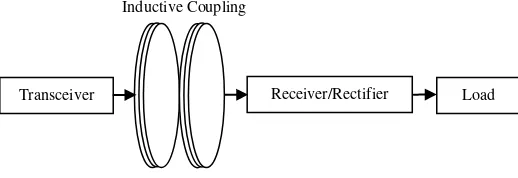
WPT can be divided into 3 parts components. First, transceiver. The transceiver electromagnetically transfers power via inductive coils which supply a wireless transfer of power to receiver units. Second, inductive coupling, the inductive coupling in this case as the antenna and forward to the bridge rectifier which act convert the induced AC voltage to the DC voltage. Third, rectifier. The rectifier finally will supplies DC voltage to the load. Block diagram of wireless power transfer as shown in Figure 1.
Inductive Coupling
Currently WPT is requirements to be implanted for gadget charger such as mobile phone, iPad, MP3 Player and other handheld devices, for example we could simply forget about USB cables, chargers and, when traveling, and will be efficiency.
2. Methodology 2.1. Simulation.
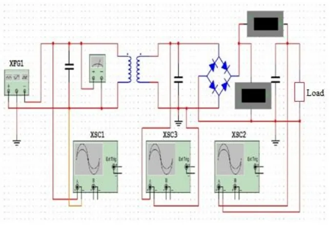
Simulation wireless power transfer has been done simulation used multisim software, as shown in Figure 2.
Figure 2. Simulation wireless power transfer using multisim software.
Multisim is an industry standard, best in class spice simulation environment. It is the cornerstone of the NI circuits teaching solution to build expertise through practical application in designing, prototyping, and testing electrical circuits.
2.2. Principle of wireless power transfer using inductive coupling.
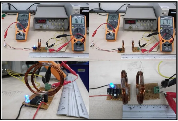
Experimental setup has been studied to get the performance of WPT. In this experiment a mobile phone devices is used as an load . The experimental setup of transceiver unit has been conducted. Energy transfer by electromagnetic induction to the receiver via inductive coupling. The voltage sources to the transceiver was provide by function generator with 1.2 MHz frequency and 0.01 of Vp-p (AC). The inductive coupling is used as the antenna to wireless power delivered from the transmitting to the input of a receiver. Receiver unit, the bridge rectifier is used convert AC voltage to produces DC voltage and produce DC output. A capacitor is included in the circuit to act as a filter to reduce ripple voltage. The experimental setup as shown in Figure 3.
ScieTech 2014 IOP Publishing
Journal of Physics: Conference Series495(2014) 012019 doi:10.1088/1742-6596/495/1/012019
Figure 3. Experimental setup and collect data
2.3. Obstacle between Transmitter and Receiver 2.3.1. A presence of hands
As shown in Figure 3. Experiment has been test using obstacle hands between the transmitter and receiver inductive coupling.
Figure 4. Experiment has been test using obstacle hands
2.3.2. A presence of book
2.3.3. A presence types of plastics
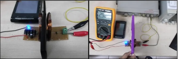
As shown in Figure 5. Experiment has been test using obstacle types of plastics (Handphone casing and Tupperware) between the transmitter and receiver inductive coupling.
Figure 6. Experiment has been test using obstacle types of plastics (Handphone casing and Tupperware)
3. Results
An experiments has been conducted to get the WPT efficiency. The transmission inductive coupling was developed with diameter 4.5 cm number of turn is 20 while the receiver using diameter 4.5 cm number of turn is 20. The distance between these two inductive coils are varied to obtain the optimum distance for wireless power transmission.
Table 1. Varied distance data vs DC output voltage and Vp-p(AC)
Distance (cm) Vp-p(AC) f (MHz) DC output
Table 1 shows the result of varied distance and the voltage differences when the distance is varied. The input source used from function generator and for wireless power transmission used frequency 1.2 MHz.
ScieTech 2014 IOP Publishing
Journal of Physics: Conference Series495(2014) 012019 doi:10.1088/1742-6596/495/1/012019
Figure 7. Graph of output voltage vs distance
Figure 7 shows the graph that has been created according to table 1. The DC output voltage getting lower as the distance are higher. From this graph we can conclude that the wireless power transmission is higher when the distance is nearer.
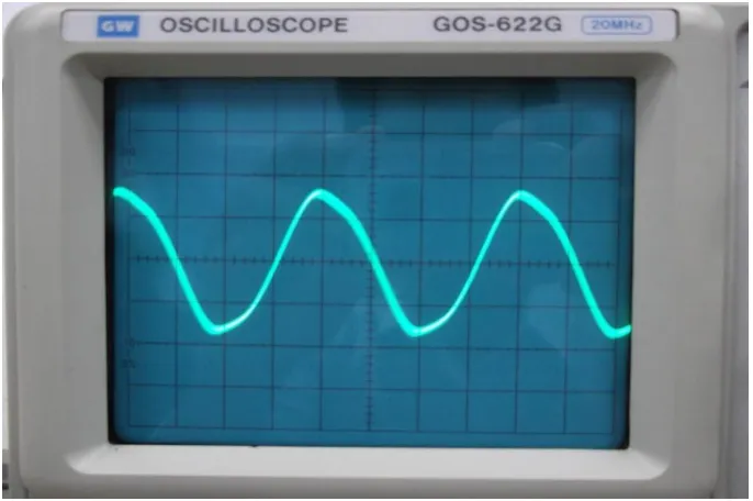
Figure 8 shows the sine waveforms at output function generator (XSC1 refer to Figure 2) with 1.2 MHz and Vp-p (AC) 0.01 V.
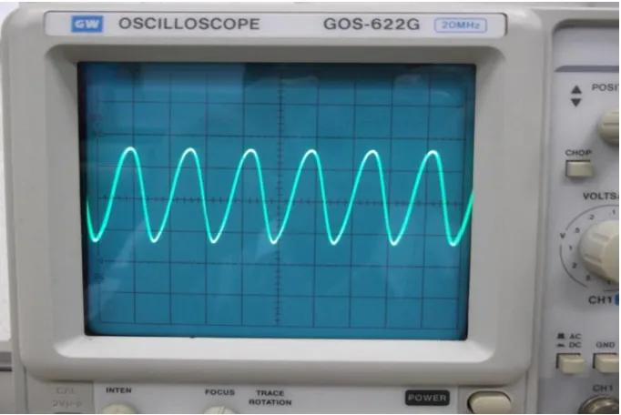
Figure 9. Voltage waveform at the inductive coupling receiver
Figure 9 shows the voltage waveform at the inductive coupling receiver terminals (XSC3 refer to Figure 2) before pass to bridge rectifier as convert AC to DC voltage.
Figure 10. DC output waveform
ScieTech 2014 IOP Publishing
Journal of Physics: Conference Series495(2014) 012019 doi:10.1088/1742-6596/495/1/012019
Conclusions
From the overall experiment conducted from wireless power transfer using inductive coupling for mobile phone charger below conclusions are deduce :
3. Base on experimental result, the distance that the power can be transmitted is up to 5 cm with 3.79 Volt, because of in this condition, the mobile phone is still can charging.
4. The wireless power transfer is not much affected by shielding materials such as the presence of hands, books and types of plastics.
5. The result shows that the wireless power transfer is suitable to be implemented for mobile phone charger.
Acknowledgement
This work was supported by Associated Professor Mohd Fareq, Muhammad Irwanto Bin Misrun, Syafruddin Hasan and Mohd Arinal is gratefully acknowledged.
References
[1] Zhen Ning Low, “Design and Test of a High Power High Efficiency Loosely Coupled Planar Wireless
Power Transfer System” IEEE transactions on industrial electronics, vol. 56, no. 5, May 2009.
[2] K. Oguri, “Power supply coupler for battery charger”, US patent 6 356049, 2000.
[3] Y. Yang and M. Jovanavic, “Contactless electrical energy transmission system”,US Patent 6 301 128,
2000.
Figure 10 displays the DC output waveform at bridge rectifier ( XSC2 refer to Figure 2) as convert AC voltage to DC voltage.