WIRELESS POWER TRANSFER MONITORING
Ahmad Faiz Bin Ahmad Azahar Bachelor of Electrical Engineering (Control, Instrumentation & Automation)
SUPERVISOR’S ENDORSEMENT
“I hereby declare that I have read through this report entitle “Wireless Power Transfer Monitoring” and found that it has complied the partial fulfillment for awarding the Degree of Bachelor of Electrical Engineering (Control, Instrumentation and Automation)”
Signature : ………
Supervisor’s Name : ………
WIRELESS POWER TRANSFER MONITORING
AHMAD FAIZ BIN AHMAD AZAHAR
A report submitted in partial fulfilment of the requirements for the degree Of Electrical Engineering (Control, Instrumentation and Automation)
Faculty of Electrical Engineering
UNIVERSITI TEKNIKAL MALAYSIA MELAKA
STUDENT DECLARATION
“I declare that that this reports entitle “Wireless Power Transfer Monitoring” is the result of
my own research expect as cited in the references. The report has not been accepted for any
degree and is not concurrently submitted in candidature of any other degree.
Signature : ………
Name : ………
IV
ACKNOWLEDGEMENT
In preparing this report, I was in contact with many people, researchers, academicians
and practitioners. They have contributed towards my understanding and thought. In particular,
I wish to express my sincere appreciation to my main project supervisor, Encik Ahmad Fairuz
Bin Muhammad Amin, for encouragement, guidance critics and friendship. I am also very
thankful to my lecturers who have been giving me guidance, advices and motivation. Without
their continued support and interest, this project would not have been same as presented here.
I am also want to thanks my family whom giving support all the way of my studies and
my University also deserve special thanks for their assistance in supplying the relevant
literatures. My fellow friends should also be recognised for their support. My sincere
appreciation also extends to all who have provided assistance at various occasions. Their
views and tips are useful indeed. Unfortunately, it is not possible to list all of them in this
V
ABSTRACT
Wireless power transfer is the transmission of electrical energy from power source to
an electrical load without conductor attached to them. Wireless transmission is useful in case
where interconnecting wire is inconvenient. The problem of wireless power transfer is
different from wireless telecommunication such as radio. The proportions of energy received
become critical only if it is too low for signal. The most common form of wireless power
transfer is carried out using direct induction follow by resonant magnetic induction. In this
project we are using resonant magnetic induction as coil of wireless power transfer. By using
two types of wires, we need to see the performance transferring power each type of wire. We
VI
ABSTRAK
Penghantar kuasa tanpa wayar adalah penghantaran tenaga elektrik dari sumber kuasa
kepada beban elektrik tanpa konduktor yang menyambung antaranya. Penghantar kuasa tanpa
wayar berguna dalam kes di mana wayar bersambung adalah menyusahkan. Masalah
pemindahan kuasa tanpa wayar berbeza daripada telekomunikasi tanpa wayar seperti radio.
Perkadaran tenaga diterima menjadi kritikal hanya jika ia terlalu rendah untuk isyarat.
Kebiasaannya, pemindahan kuasa tanpa wayar dijalankan menggunakan induksi sendiri dan
diikuti salunan aruhan magnet. Dalam projek ini, kita menggunakan salunan aruhan magnet
dengan menggunakan dua jenis wayar iaitu wayar tembaga biasa dan wayar enamel tembaga.
Dengan menggunakan dua jenis wayar ini, kita perlu melihat prestasi pemindahan kuasa setiap
VII
TABLE OF CONTENT
CHAPTER TITLE PAGE
ACKNOLEDGEMENT ABSTRACT
IV V TABLE OF CONTENT
LIST OF TABLE LIST OF FIGURE
VII IX
X
1 INTRODUCTION
1.1 Overview 1
1.2 Project Motivation 2
1.3 Problem Statement 2
1.4 Objective
1.5 Scope Of Project
1.6 Report Outline
3
3
4
2 LITERATURE REVIEW
2.1 Overview 6
2.2 Early History Of Wireless Power Transfer 6
2.2.1 Heinrich Hertz 7
2.2.2 Nikola Tesla 7
VIII
3 METHODOLOGY
3.1 Overview 9
3.2 Project Flow Chart 10
3.3 Operating Principles 11
3.4 Magnetic Resonance Coupling
3.5 Labview
3.6 Wireless Power Transfer Circuit
3.7 Type Wire For Wireless Power Transfer Coil
3.7.1 Copper Wire Coil
3.7.2 Enamel Copper Wire Coil
12 16 17 18 18 19
4 RESULT
4.1 Overview 20
4.2 Experiment Transfer Power Using Normal Copper Wire
4.3 Experiment Transfer Power Using Enamel Copper Wire
20
26
5
6
ANALYSIS AND DISCUSSION 5.1 Overview
5.2 Analysis Of Power Transfer
5.3 Efficiency Of Resonance Coil
5.3.1 Percentage Normal Copper Coil
5.3.2 Percentage Enamel Copper Coil
CONCLUSION AND RECOMMENDATION 6.1 Overview
6.2 Conclusion
6.3 Recommendation
IX
LIST OF TABLES
TABLE TITLE PAGE
Table 4.1 Voltage vs Distance for normal copper wire. 21
Table 4.2
Table 5.1
Table 5.2
Table 5.3
Table 5.4
Table 5.5
Voltage vs Distance for Enamel Copper Wire.
Voltage vs Distance for Normal Copper Wire Coil.
Voltage vs Distance for Enamel Copper Wire Coil.
Difference Voltage between the Coils.
Efficiency of Copper Wire Coil vs Distance
Efficiency of Enamel Copper Wire Coil vs Distance.
26
32
33
34
36
X
LIST OF FIGURES
FIGURE TITLE PAGE
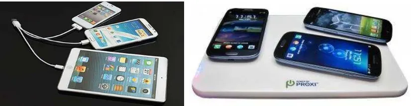
Figure 1.1 Comparison of using wire charging and wireless power transfer charging.
3
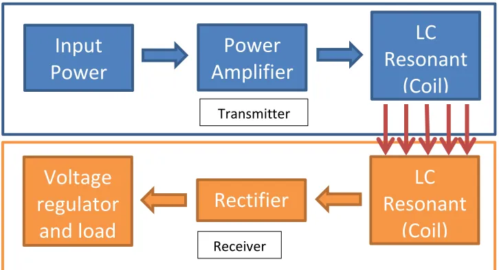
Figure 2.1 Basic Block Diagram of Wireless Power Transfer. 8
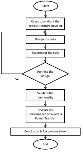
Figure 3.1 Flow chart for the methodology of the Project. 10
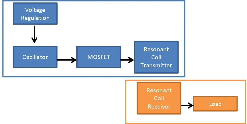
Figure 3.2 Block diagram of wireless power transfer system 11
Figure 3.3 Example of a resonator 12
Figure 3.4 Solenoid form for coil 13
Figure 3.5 Figure 3.6 Figure 3.7 Figure 3.8 Figure 3.9 Figure 3.10 Figure 3.11
Equivalent circuit for the couple resonator
Example UI component in LabVIEW.
Circuit from Proteus before etching.
Circuit receiver from Proteus before etching.
Circuit for wireless power transfer.
Normal Copper Wire Enamel Copper Wire
15 16 17 17 18 19 19
Figure 4.1 Copper wire at transmitter using LabVIEW. 21
Figure 4.2 Figure 4.3 Figure 4.4 Figure 4.5 Figure 4.6 Figure 4.7
Copper wire at receiver using LabVIEW.
Copper wire at transmitter.
Copper wire at receiver at distance 0cm.
Copper wire at receiver at distance 2 cm.
Copper Wire at receiver at distance 4 cm.
Copper Wire at receiver at distance 6 cm.
XI Figure 4.8 Figure 4.9 Figure 4.10 Figure 4.11 Figure 4.12 Figure 4.13 Figure 4.14 Figure 4.15 Figure 4.16 Figure 4.17 Figure 4.18 Figure 5.1 Figure 5.2 Figure 5.3 Figure 5.4 Figure 5.5
Copper Wire at receiver at distance 8 cm.
Copper Wire at receiver at distance 10 cm.
Enamel wire at transmitter using LabVIEW.
Enamel wire at receiver using LabVIEW.
Enamel wire at transmitter.
Enamel wire at receiver at distance 0 cm.
Enamel wire at receiver at distance 2 cm.
Enamel wire at receiver at distance 4 cm.
Enamel wire at receiver at distance 6 cm.
Enamel wire at receiver at distance 8 cm.
Enamel wire at receiver at distance 10cm
Visual Difference Voltage from Table 5.3.
Different Voltage at receiver of two type wire coil.
Efficiency of Copper Wire Coil vs Distance
Efficiency of Enamel Copper Wire Coil vs Distance.
Difference Efficiency of Each Type of Coil.
1
CHAPTER 1
INTRODUCTION
1.1 Overview
Nowadays technologies growing rapidly and many of the companies produce the latest
gadget that suits in modern world. People will buy the gadget to make their life comfortable.
Many of gadgets at certain area will face a problem of having many wires that sharing a limited
amount of power socket, it also will make the wires become unmanageable and scattered. Hence,
with the idea of Nikola Tesla, wireless power transfer is invented.
Wireless power transfer can be applied or used in our daily live to get more manageable
or tidy area that free of wires. It also can be used in other area such as medical machine,
industrial machine, electric car and other things. Wireless power transfer is easy to manage
without affecting user health.
In this chapter will be discussing on project motivation, project objective, problem
2
1.2 Project Motivation
The motivation for wireless power transfer system comes from wires complex and
untidy. With a large number of gadgets are using nowadays that focus on smartphone, there are
demands for convenience in managing their power supplies. Other than that, it can help user
easily to use technology at anywhere and anytime without worrying their battery draining
quickly on their smartphone.
1.3 Problem Statement
Most of the people use gadgets to improve their daily routine work. Most of the gadget
are using power socket as their power supply. If they use too many gadgets in their daily life it
will cause lack of power socket. Nowadays, people are using smartphone to make their life
easier. The problem they facing are the life time or standby time of smartphone battery is
draining quickly with using multi-application usage. To overcome the problem is wireless power
transfer were invented by Nikola Tesla in 1893, where he demonstrate the illumination of
vacuum bulb without using wires. Wireless power transfer is used for exchanging the power
through the resonance coil. Figure 1.1 shows the comparison of using wire charging and wireless
power transfer charging. The difference is the wireless power transfer charging is more tidy and
manageable, it also make user more confortable to using smartphone without charging using
wires.
The problem need to be highlight in this project are does the wireless power transfer can
transferring power in the long range or only for a short range. Then, the performance of wireless
power transfer can be effect from the material that been used in coil.
Wireless power transfer needs to be implemented in our life. It will make people use
gadget for better life. In this project, an experiment need to carried out on analytical and prove
3
In other hand, we need to consider the health environment of radiation of wireless power
transfer.
Figure 1.1: Comparison of using wire charging and wireless power transfer charging.
1.4 Objective
There are several objectives that need to be achieved in order to make this project
successfully.
To investigate a wireless power transfer system using a resonant coil. To develop and study the system and test it to establish its functionality.
To validate the performance coil of wireless power transfer using LabVIEW Software.
1.5 Scope of the project
The scope of this project is:
Using only normal copper wire and enamel copper wire to do resonant coil on the
4
Develop the wireless power transfer system using a hardware and analytical by using existing circuit that had been commercial.
The project only focused performance of the system with two type of material on the
coil.
1.6 Report Outline
In this section, the outline of project report is presented. This report includes of five
chapters and each chapter is explained.
Chapter 1 discusses on introduction regarding to the wireless power transfer system. The problem statement, objectives and significant of project are stated briefly and clearly.
Chapter 2 discusses the literature review on wireless power transfer systems. History of wireless power transfer.
Chapter 3 discussing more about the methodology of wireless power transfer system. The flow charts of project are listed by following the sequence in phase 1 and phase 2.
Chapter 4 representing the result from an experiment of normal copper wire coil and enamel copper wire coil.
5
6
CHAPTER 2
LITERATURE REVIEW
2.1 Overview
Wireless power transfer system has been attempted many times throughout the last past
centuries. The concept ideas were began from the experimented of Heinrich Hertz and Nikola Tesla around year 1890’s and has continued until this day. Although Nikola Tesla was confident with his hypothesis to transfer power and nobody has been able to validate the idea. Nowadays,
wireless power transfer is largely exhibited through induction. Although the functional of
wireless power transfer through induction is constrained to a very small distances. In this chapter
provides a literature review of history of wireless power transfer.
2.2 Early History of Wireless Power Transfer
The early history of wireless power transfer involves of two main inventors namely
7
2.2.1 Heinrich Hertz
Heinrich Hertz was born in Hamburg, Germany on 22th February 1857. Heinrich Hertz
was gifted not only in school but also as a mechanic, sculptor, draftsman, linguist, and athlete
(Susskind 1988). Heinrich Hertz studied at numerous university, most prominently studying at
the university of Berlin under Hermann Helmholtz (Susskind, 1988). Hertz proved that
electricity can be transmitted in electromagnetic waves. Heinrich Hertz died on 1st January 1894
at the age of 36. [2]
2.2.2 Nikola Tesla
Nikola Tesla was born in the stroke of midnight 9th July 1856 in Yugoslavia. Nikola
Tesla had a special give of being able to imagine things so well that they seemed real. This
allows him to build mental rather than physical prototypes that led to successful finished designs.
The downside to this was that Nikola Tesla took very poor notes, he only wrote down those
things that he deemed absolutely necessary. Nikola Tesla was far beyond his time in his experimentations. It wasn’t until 1970 that Robert Golka became the first to replicate the Tesla coil.
In 1899, Nikola Tesla went to Colorado Springs to build a laboratory and try out some
new ideas. One of these ideas was the wireless transmission of power. In his experiment he was
able to light 20 lamps, 26 miles away from his lab.
Nikola Tesla theory of wireless transmission of power was a little different than today’s vision; it was centred on his consideration of the earth as a giant conductor. Nikola Tesla died on
8
2.3 Basic Principles of Wireless Power Transfer.
Radio was invented by a person name Nikola Tesla also known “Father of Wireless”, [1] he is the one who the first person that conceived the idea of transmitting power through the air has been around for over century, with the Nikola Tesla’s pioneer idea and his experiments attempts to do so. Most of the approaches to wireless power transfer are using an electromagnetic
(EM) field of some of frequency as the means by which the energy is sent. [1] Figure 2.1 shows
the simple block diagram of wireless power transfer.
There are three type of wireless power transfer that can use in wireless power transfer
that is radiative transfer, inductive coupling and resonant coupling. [4] Radiative transfer are
suitable to exchange information and transfer a small power in miliwatts, most of it were wasted
into free space. For inductive coupling, it can be transmitted the power with high efficiency but
in very short distance.
Last type is resonant coupling, it can transfer high power at medium distance. Basic
principle is that two separate coils with the same resonant frequency are possible to form a
resonant system based on high frequency magnetic coupling and exchange power in high
efficiency. [4]
9
CHAPTER 3
METHODOLOGY
3.1 Overview
In this chapter the main topics that will be discussed is the methodology and approaches
used to complete this project. In this experiment, loop coils, and the performance wireless power
transfer system will be analysed. This topic will consist:
i. Project flow chart
ii. Case study wireless power transfer using magnetic resonance coupled.
iii. Experiment on wireless power transfer coils
iv. Develop the system and validate the performance.
v. Analyse result
10
3.2 Project Flow Chart
Figure 3.1 show the project flow chart used to make sure this project is successfully done
before the due date of this project:
No
Yes
Figure 3.1: Flow chart for the methodology of the Project. Start
Case study about the topic (Literature Review)
Design the coils
Experiment the coils
Validate the functionality.
Running the design
Analyze the performance of Wireless
Power Transfer
Conclusion & Recommendation
11
3.3Operating Principles
The principles of operation of wireless power transfer system are very similar to the
surface based wireless power transmission system used for communication within robot swarms
[9]. In a resonant system, the circular current in the resonant coil is greater that the drive coil by
the quality factor, Q. Wireless power transfer system circuit use power MOSFET to get a desired
transfer frequency. Figure 3.2 show the block diagram of wireless power transfer transmitter.
Figure 3.2: Block diagram of wireless power transfer system
A time varying current flows in a coil transmitter that is coupled with a resonance LC
receiver coil. Current is induced in receiver coil at the transmission frequency, which set as
resonance frequency. The resonance frequency can be calculated from the inductance and
capacitance of LC circuit.
Voltage Regulation
Oscillator MOSFET
Resonant Coil Transmitter
Resonant Coil
12
3.4 Magnetic Resonance Coupling
Resonance is a phenomenon that occurs in nature in many different forms, it involves
energy oscillating between two modes. In a system at resonance, it possible to have large
build-up of stored energy having only a weak excitation to the system and it occurs if the rate energy
inject into the system is greater than the rate of energy loss by the system.[6] Figure 3.3 is the
example circuit for resonator
The behaviour of an isolated resonator can be defined by two fundamental parameters, its
resonance frequency, and its intrinsic loss rate, . The ratio of these two parameters define
the quality factor or Q of the resonator (Q = /2 ) a measure of how well it stores energy.
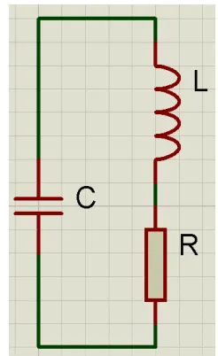
Figure 3.3: Example of a resonator
In this wireless power transfer will use magnetic resonance coupling method, this method
has an advantage of transmit power in a long distance with a highly efficiency and robust to
positional shift of transmitting and receiving antenna or also known coil. [4] The coil concept