UNIVERSITI TEKNIKAL MALAYSIA MELAKA
DEVELOPMENT OF MULTIPLE WIRELESS POWER TRANSFER
SYSTEM
This report submitted in accordance with requirement of the Universiti Teknikal Malaysia Melaka (UTeM) for the Bachelor Degree of Engineering Technology
(Bachelor’s Degree in Electronic Engineering Technology) (Telecommunications with Hons.)
by
AMIRUL REZZA BIN ISHAK B071210095
910915-05-5265
ii
DECLARATION
I hereby, declare this report entitled “Development of Multiple Wireless Power Transfer” is the results of my own research except as cited in references.
Signature : ………...
Author’s Name : AMIRUL REZZA BIN ISHAK
iii
APPROVAL
This report is submitted to the Faculty of Engineering Technology of UTeM as a partial fulfilment of the requirements for the degree of Bachelor of Electronic Engineering Technology (Telecommunications) with Honours. The member of the supervisory is as follow:
Signature : ……….
iv
ABSTRAK
v
ABSTRACT
vi
DEDICATION
vii
ACKNOWLEDGEMENT
viii
2.1.1 Optimal Operation of Contactless Transformers ... 7
2.1.2 Wireless Power for Mobile ... 8
ix
2.2 Magnetic Field and Electric Current ... 11
2.3 Nominal Specification for Charging Battery ... 12
CHAPTER 3 ... 14
3.0 Introduction ... 14
3.1 Flow Chart of the Project ... 15
3.2 Methodology ... 16
3.3 Hardware and Software Requirement ... 17
3.3.1 Hardware Requirement ... 17
3.9 Development of Multiple Wireless Power Transfer ... 25
3.9.1 Transmitter Circuit ... 26
3.9.2 Receiver Circuit ... 32
3.10 Flowchart of Methodology Process ... 35
CHAPTER 4 ... 37
4.0 Introduction ... 37
4.1 Implementation ... 37
x
4.2.1 Transmitter Circuit ... 39
4.2.2 Receiver Circuit ... 42
4.3 Printed Circuit Board Development ... 44
4.3.1 PCB Layout of Transmitter Circuit ... 45
4.3.2 PCB Layout of Receiver Circuit ... 46
4.4 Hardware Construction ... 48
4.4.1 Design Project ... 48
4.4.2 Circuit Construction ... 50
4.4.3 Development of Prototype ... 51
4.5 Measure Result Analysis ... 52
4.6 Troubleshoot Circuit ... 54
4.7 Discussion ... 56
CHAPTER 5 ... 57
5.0 Conclusion ... 57
5.1 Recommendation ... 58
REFERENCES ... 59
xi
LIST OF FIGURES
Figure 1.1: Drawing of condition for wireless power transfer to mobile devices... 3
Figure 2.1: Block diagram of the contactless charging system ... 7
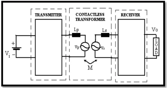
Figure 2.2: The equivalent circuit model of contactless transformer... 8
Figure 2.3: Input impedance spectra couplings of two typical resonances ... 9
Figure 2.4: Impacts coil to coil efficiency ... 10
Figure 2.5: Right Hand Grip Rule ... 11
Figure 3.1: Flow Chart Project ... 15
Figure 3.2: Transmitter Circuit Diagram ... 18
Figure 3.3: Receiver Circuit Diagram ... 19
Figure 3.4: Simulation Results by Multisim Software ... 20
Figure 3.5: The Fabrication Process ... 23
Figure 3.6: Block Diagram of Multiple Wireless Power Transfer System ... 25
Figure 3.7: Power Conversation Unit ... 26
Figure 3.8: The Adapter 12 VDC ... 27
Figure 3.9: MOSFET IRFZ44N ... 28
Figure 3.10: Half Bridge Inverter... 29
Figure 3.11: The Simple Parallel Resonant Circuit. ... 30
Figure 3.12: Primary Coil Design ... 30
Figure 3.13: AWG Coil ... 32
Figure 3.14: Receiver Side ... 32
Figure 3.15: A Full-Wave Rectifier Circuit Using 4 Diodes ... 33
Figure 3.16: LM7805 Pin Out Diagram ... 34
Figure 4.1: Step How to Use The System ... 38
Figure 4.2: AC Signal Resulting in a Form of Sine Wave ... 40
Figure 4.3: Transmitter Circuit ... 40
Figure 4.4: Output Voltage across Primary Coil in Transmitter Circuit ... 41
Figure 4.5: Receiver Circuit ... 42
Figure 4.6: Output Waveform across Secondary Coil in Receiver Circuit ... 43
Figure 4.7: Simulation Output for Receiver Circuit ... 43
Figure 4.8: PCB Layout of Transmitter Circuit ... 45
Figure 4.9: Back View of Transmitter Layout ... 45
Figure 4.10: Front View of Transmitter Layout... 46
Figure 4.11: PCB Layout of Receiver Circuit ... 46
Figure 4.12: Back View of Receiver Layout ... 47
Figure 4.13: Front View of Receiver Layout ... 47
Figure 4.13: Front View of Receiver Layout ... 47
Figure 4.14: Designing Copper Coil for Transmitter and Receiver Circuit ... 48
Figure 4.15: Relationship between Number of Turns and Induced Voltage... 49
xii
Figure 4.17: Transmitter Module ... 50
Figure 4.18: Receiver Module... 50
Figure 4.19: Installing Transmitter Module and Receiver Module into Casing ... 51
Figure 4.20: The Analysis of Range to Charge a Device ... 53
Figure 4.21: Troubleshoot on Receiver Circuit... 54
Figure 4.22: Dropping of Input Voltage ... 55
xiii
LIST OF TABLE
Table 2.1: Nominal Specifications for Lithium-ion Rechargeable Cell ... 13
Table 3.1: Dimensions of the Primary Coil ... 31
Table 3.2: Specification AWG Wire ... 31
Table 4.1: Output Voltage of Transmitter Circuit by Simulation ... 41
Table 4.2: Induced Voltage of Receiver Circuit ... 44
Table 4.3: The Analysis in Designing Coil ... 48
Table 4.4: Input and Output of Coils ... 52
1
CHAPTER 1
INTRODUCTION
1.0 Introduction
Nowadays is a world of technological advancement .A new technologies has implement in worlds today .Each and every day a technology have been created which is to make our life more easier and faster. With all of these, humans still using on the classical and type of wire system to charge our devices everyday which is currently use low power devices such as mobile phones, digital camera .In addition using a wire have been mess up. It also takes up a lot of electric sockets and space which is its make more difficult to use for other electronic appliances. The idea solution to all these difficulty have been comes out, with using an inductive coupling concept, a simple and effective way of transferring power wireless have been created.
This chapter introduces overview and background of this project with the title “Multiple Wireless Power Transfer System”. This project is using a resonant inductive coupling technique. One of the main purpose of this project is to compare different wireless power transfer against others WPT system.
2
1.1 Background Project
Wireless power transfer (WPT) is the transmission of electrical power that form a source called electromagnetic without using conducting wires or other electronic devices .To develop this project ,it have been divided into two parts ,first the transmitter circuit and secondly the receiver circuit which is the transmitter circuit is connected to the primary coil while the receiver circuit is connected to secondary coil .The power transmitter and receiver circuit will simulate and made into hardware .So in this project a voltage ,current ,power and distance will be analysed while during this project. To demonstrate the power was successfully transferred to wirelessly technique, a mobile phone is used to make it charged and there are multiple of loads that is used in this wireless power transfer systems.
Multiple wireless power transfer is the transmission of electrical power that obtain from a source of an electrical load without using of conducting wires or materials ,it just use a magnetic resonance coupling technology to implement its charging by transmitting the current that converting electromagnetic flux to form an electric field to produce current. The industry realizes that demand of using a wireless power charging which is to create a mobile device that can be charged more easily without using a connecting wire.
3
Figure 1.1: Simplified drawing of condition for wireless power transfer to mobile devices.
The system is divided into two part which is the transmitter circuit will provide power to the wireless transfer and the receiver circuit. Circuit that contains the primary coil will be transmitting the power through the power transmitter. To induce a magnetic field between the two coils a Dc to AC and series resonant capacitor inverter will be used to invert DC power to AC.A two halves of a resonant transformer will be produced through the primary and secondary coils. To demonstrate that power was successfully transferred wirelessly, a mobile phone was charged and there are multiple loads in wireless power transfer systems. The amount of power transmitted and effectively received will depend on how well the coils are designed.
4
1.2 Problem Statement
Current wireless power transmitters of wireless power transfer (WPT) are usable to transmitting the source of current that convert electromagnetic flux to form an electric field. The difference in this WPT technique and the new concept of wireless power system is, it able to send power source as wireless with over longer distances to multiple receiver. This gives it an advantages gain value on the market.
A WPT that has been largely undiscovered is the ability to charge batteries and other electronic portable devices .In addition while wireless power devices have already been created by other companies and institute. They are still in basic trending and are not practically explored. A mobile user are not only feel disappointed when their battery is drain too fast or corrupt ,but they are also concern about the cost of electric bills that have been demand and high paid nowadays. There is some concern based on recently use of wireless power transfer techniques. Firstly, today most rechargeable or any portable electronic devices arrive with their own designed charger and cables. An average user that have been analysed in the world, it stated that each user of mobile electronic devices carries at least three of different chargers.
1.3 Objectives
The main objective of this project is to build a multiple wireless power transfer. In order to make this project successful, the objectives have been declared these objectives must be achieved in completing this project. Objectives are a guidance of any project, so the objectives have been listed below.
1. To study a system that was capable of charging a mobile phone using the resonant inductive coupling technique power transfer.
5
1.4 Scope of Project
6
CHAPTER 2
LITERATURE REVIEW
2.0Introduction
In this chapter, reviews of the previous researches project and existing literature that are related with this project will be discussed. The information will be become additional source for the project in becoming more successful. To have a brief understanding of the researches related to the project, a few literature reviews had been done. This chapter will describe the related literature reviews. It introduces the framework for the case study that comprises the main focus of the research described in this project. There are previous researches on resonant inductive coupling operation.
7
2.1.1 Optimal Operation of Contactless Transformers
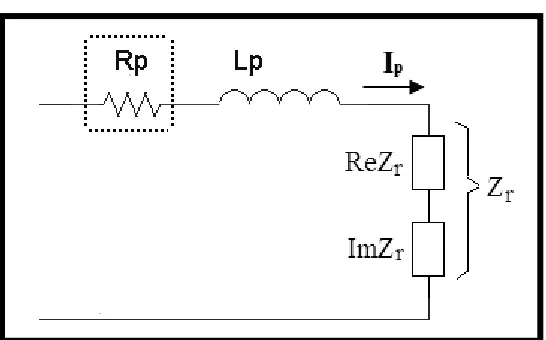
In this paper, a boundary frequency is found for optimal operation of contactless transformers under different loading conditions that have found by (W.M. Ng, K.K. Lee and S.Y.R.). To improve it sustain energize, at the secondary side will be adding an external capacitor in series or in parallel with the secondary winding. The equivalent circuit of contactless transformer are shown in Figure 2.2(a).Primary coil and secondary coil circuit are used to present the inductance of primary winding and secondary winding, respectively. The capacitor will be added at the secondary side is Cs in Figure 2.2(b), which can be replaced in series or in parallel with the secondary winding. RL is stands for equivalent to the resistor of the load.Figure 2.1 shows the equivalent circuit of the primary side with reflected impedance from the secondary circuit called Z r.
8
(a) Coupled model
(b) Primary side with reflected impedance
9
2.1.2 Wireless power for mobile devices
A major part of this paper is to refers previous data from others publication on efficiency limits and cites from a further one, but new aspects about resonance operation and magnetic emissions are also added up that have been discovered by E.Waffenschmidt . In a further part of this work, an inductive power transmission pad is applied, which is it need to charge devices like mobile phones. Finally, the Wireless Power Consortium is discovered, which is it’s recently released the first industry standard for inductive charging of mobile devices called “Qi”, and have been reviewed in this paper. Figure 2.3 shows the input current (for a fixed voltage) at the part of transmitter coil shows a typical inductive power system, where the receiver comprises a series resonant capacitor.
Figure 2.3: Input impedance spectra for different couplings showing two typical resonances.
Its shows that an input impedance spectrum that provide a different coupling of typical resonances transfer the power that is induced are not really stable because the efficiency is low. To maintain the energy wireless inductive power transfer, a
10
2.1.3 Understanding Wireless Power
In this paper that have been discovered by David W.Baarman by a book that he write in 2009, he says that to develop a wireless power technology to consumers, its need to take more understanding of the different embodiments of wireless power technology, as well as clearly same definition as efficiency safety including pad and adapter solutions and a wireless power specification. Moreover, this paper discussed about mid-range technology. A mid-range wireless power is built around the idea by using resonant magnetic induction or near-field concept. The limitations to transmit the electromagnetic of this concept start with the diameter between the transmitter and receiver. In addition, an inductive coupled system can transmit charge between diameter of the transmitter and receiver. The figure 2.4 shows that mid-range or near-field functioning as a peak efficiency range that is fairly close to the proximity although it has extended range.
Figure 2.4 : Impacts coil to coil efficiency.
Although the mid-range is extended, the range of peak efficiency also will be extended in a smaller range. This happens when the initial commercialization technology is evolves. Large fields and higher frequencies will provide specific benefits which are the susceptibility issues will require further investigation and consideration.
11
A magnetic field is produce with all moving charged particles. A moving charge is known as electrons which produce magnetic field that depend on the charge, velocity, and acceleration of the particles. The direction of magnetic field is determined by using ‘The Right Hand Rules’. The rule is used in two type of applications that use in a Ampere Law. Figure 2.5 shows a Right Hand Grip Rule.
i. An electric current passes through a solenoid, a magnetic field will occur. When someone wraps his/her right hand around the solenoid with their fingers, the direction of the conventional current will happens, the thumb points show the direction of the magnetic north pole.
ii. An electric current passes through a straight wire. Here, the thumb points in the direction will flow the current (from positive to negative), and there will be fingers point in the direction that show the magnetic lines of flux.
Figure 2.5: Right Hand Grip Rule.
The strength of the magnetic field will decrease if it distance is real apart from its wire. The magnetic field inside the loop will weaken the concentrates of the magnetic field if the wire is bending.