i
DESIGN AND DEVELOPMENT OF POWER INVERTER FOR INDUCTIVE POWER TRANSFER (IPT)
SYAHIDAH BINTI NASRUDIN
This report is submitted in partial fulfillment of the requirements for the award of Bachelor of Electronics Engineering (Industrial Electronics)
Faculty of Electronic and Computer Engineering Universiti Teknikal Malaysia Melaka (UTeM)
ii
Saya SYAHIDAH BINTI NASRUDIN
mengaku membenarkan Laporan Projek Sarjana Muda ini disimpan di Perpustakaan dengan syarat-syarat kegunaan seperti berikut:
1. Laporan adalah hakmilik Universiti Teknikal Malaysia Melaka.
2. Perpustakaan dibenarkan membuat salinan untuk tujuan pengajian sahaja.
3. Perpustakaan dibenarkan membuat salinan laporan ini sebagai bahan pertukaran antara institusi pengajian tinggi.
4. Sila tandakan ( √ ) :
SULIT*
*(Mengandungi maklumat yang berdarjah keselamatan atau kepentingan Malaysia seperti yang termaktub di dalam AKTA RAHSIA RASMI 1972)
TERHAD** **(Mengandungi maklumat terhad yang telah ditentukan oleh
organisasi/badan di mana penyelidikan dijalankan)
TIDAK TERHAD
Disahkan oleh:
__________________________ ___________________________________
iii
“I hereby declared that this progress reporntitled “Design and Development of Power Inverter for Inductive Power Transfer (IPT)” is the result of my own work except as
cited in the references.”
iv
“I hereby declared that I have read through this progress report entitled “Design and Development of Power Inverter for Inductive Power Transfer (IPT)” and found that it
has comply the partial fulfillment for awarding the degree of Bachelor of Electronic Engineering (Industrial Electronic)”.
v
Dedicated to my beloved family especially my mother and to my friends who give me the encouragement and support to complete this project. Besides, millions of thanks to
vi
ACKNOWLEGDEMENT
Assalamualaikum W.B.T.. Alhamdullillah, Praise to Allah S.W.T for his blessing and guidance have helped me in completing my thesis. I would like to express my gratitude to my supervisor, Pn. Yusmarnita Binti Yusop and to my co-supervisor DR.Mohd Shakir Bin Md Saat for guiding me throughout the project. Furthermore, they also give their suggestions and ideas throughout my final year project from the beginning until I have fully completion this project. Theirs professionalism, guidance, energy, humour, throughness, dedication and inspiration will always serve to me as an example of the perfect supervisor-cheers.
Besides, I would also like to thanks to my family especially for my mother, Saadiah binti Maadom cause give me the continuous support along completing this project. I also want to dedicate my gratitude to my sibling, Azimah inti Nasrudin, Muhammad Faizal Bin Nasrudin, and Nur Syuhada Binti Nasrudin cause their fully care and help made me no worries at all time to make this project.
vii
ABSTRAK
viii
ABSTRACT
ix
TABLE OF CONTENTS
CHAPTER CONTENT PAGE
Title i
Report Verification Form ii
Student Verification Form iii
Supervisor Verification Form iv
Dedication v
Acknowledgement vi
Abstract vii
Abstrak viii
Table of Contents ix
List of Tables xii
List of Figures xiii
List of Abbreviations xvii
List of Appendices xviii
I INTRODUCTION 1
1.1 Introduction of Project 1
1.2 Problem Statement 3
1.3 Objectives 3
1.4 Scope of Project 4
xi
4.4 Measured Output Voltage by using difference turn of coil 38 4.4.1 10 turns of coil as primary and 30, 20, 10 turn 38
4.4.7 Analysis of output power and efficiency 59
xii
LIST OF TABLES
NO TITLE PAGE
Table 4.1 Operation of the converter 32
Table 4.2 Number of turn that measured 38
Table 4.3 10 turns of coil as primary and 30, 20, 10 turn coil as secondary 38 Table 4.4 20 turns of coil as primary and 30, 20, 10 turns coil as secondary 40 Table 4.5 30 turns of coil as primary and 30, 20, 10 turn coil as secondary 41 Table 4.6 The current measured by adjusting the distance between coils 42 Table 4.7 The power measured by adjusting the distance between coils 44
10(p)-30(s)
Table 4.8 The power measured by adjusting the distance between coils 45 10(p)-20(s)
Table 4.9 The power measured by adjusting the distance between coils 46 10(p)-10(s)
Table 4.10 The power losses and efficiency measured by adjusting the 59 distance between coils 10(p)-30(s)
Table 4.11 The power losses and efficiency measured by adjusting the 60 distance between coils 10(p)-20(s)
xiii Figure 2.6 The ideal waveforms for 100% of efficiency for voltage and 12
current
Figure 2.7 The schematic of diode bridge rectifier circuit 13 Figure 2.8 The current flow in Bridge Rectifier for Positive Half cycle 14 Figure 2.9 The current flow in Bridge Rectifier for Negative Half Cycle 15 Figure 2.10 The calculation of multi layer air core inductor 16
Figure 2.11 Magnetic flux in coils without core 17
Figure 2.12 Magnetic flux in coils using a ferrite core 17 Figure 2.13 Coupling coefficient VS Air gap for coils with ferrite core and 18
coils in the air
Figure 3.1 Flow chart of overall methodology 20
Figure 3.2 The flowchart of the system 22
Figure 4.1 The overall project of IPT system 25
xiv
ltspice software
Figure 4.3 The boost converter results in theoretical by using ltspice software 28 Figure 4.4 The simulation of boost circuit on the breadboard 29 Figure 4.5 The Boost converter result in practical by using oscilloscope 29 Figure 4.6 Boost circuit by using Proteus software 30 Figure 4.17 The simulation of Rectifier circuit on the breadboard 36 Figure 4.18 The result of rectifier waveform in theoretical by using multisim 36
Figure 4.19 Rectifier circuit by using Proteus 36
Figure 4.20 The number of coil is 30 turns 37
Figure 4.21 The number of coil is 20 turns 37
Figure 4.22 The number of coil is 10 turns 37
Figure 4.23 Graph for output voltage when the primary is 10 numbers of turns 39 and the secondary is 30, 20 and 10 numbers of turns
Figure 4.24 Graph for output voltage when the primary is 20 numbers of turns 40 and the secondary is 30, 20 and 10 numbers of turns
xv
and the secondary is 30, 20 and 10 numbers of turns
Figure 4.26 Graph for output current when the primary by adjusting the distance 43
between coil Figure 4.27 Graph for output power when the primary is 10 numbers of turn 44
and the secondary is 30 numbers of turns Figure 4.28 Graph for output power when the primary is 10 numbers of turns 45
and the secondary is 20 numbers of turns Figure 4.29 Graph for output power when the primary is 10 numbers of turns 46
and the secondary is 10 numbers of turns Figure 4.30 The measurement when the distance between coils is 4.0cm 47
Figure 4.39 The measurement when the primary coil is 10turn and secondary 50
is 30 turns.
xvi
Figure 4.50 The measurement when the distance between coils is 4cm 55
Figure 4.51 The measurement when the distance between coils is 3.5cm 55
Figure 4.52 The measurement when the distance between coils is 3.0cm 55
Figure 4.53 The measurement when the distance between coils is 2.5cm 56
Figure 4.54 The measurement when the distance between coils is 2.0cm 56
Figure 4.55 The measurement when the distance between coils is 1.5cm 56
Figure 4.56 The measurement when the distance between coils is 1.0cm 57
Figure 4.57 The measurement when the distance between coils is 0.5cm 57
Figure 4.58 The measurement when the distance between coils is 0cm 57
xvii
LIST OF ABBREVIATIONS
IPT - Inductive Power Transfer CPT - Capacitive Power Transfer WPT - Wireless Power Transfer FWR - Full Wave Rectifier HWR - Half Wave Rectifier FYP - Final Year Project
P - Primary
xviii
LIST OF APPENDICES
NO TITLE PAGE
A DATA SHEET OF MOSFET IRF 530 67
B DATA SHEET OF MOSFET IRF 510 69
1
CHAPTER 1
INTRODUCTION
1.1 Introduction of Project
Nowadays, many electronic devices are invented. Such devices are described in Practical Electronic books, Project Books and over the Internet. These gadgets help make our lives easier. Many people now are using them in their fields of study or projects. Electronic devices ease and simplify everything that already done. This chapter will discuss briefly about the project introduction that consist of problems statement, objectives, scopes and methodology of the project.
In this high technology world, the advanced technology has generally variety of portable electronic devices. The mobile phone, gadget and laptop are the examples of the growth technology. However, users still needed to plug in these devices manually when the battery used is the lower charger. As for this current issue the wireless power transfer (WPT) is proposed to identify the possibility of connector battery wirelessly.
2 across an air gap using induction coils. There are various types of WPT technologies which are Capacitive Power Transfer (CPT), Induction Power Transfer (IPT), light and etc. In this project, the IPT system has been proposed [12].
This IPT system is based on the fundamental of Faraday and Ampere law. This is function of alternating magnetic fields to transfer power from a primary winding to a secondary winding. Other than that, in order to protect and preserve the world natural resources the power source can be replaced with the solar source. Usually energy that has been produced is everywhere and anywhere in the surrounding, which is solar energy are categorized as natural energy sources where it used in high power application such as actuate a solar panel car, factory and etc. The illustration of process of WPT is shown in Figure 1.1.
Figure 1.1: Process of Wireless Power Transfer
3 overload and not appropriate for single phase user .The effective power transfer is very important because the secondary coil is the types of material determine the amount of power transferred. In that case the power supply is of special concern. This is because in a number of cases where batteries are used, the energy content is too low and batteries have a limited life time.
Since the energy yield will be too low for various applications even if energy scavenging techniques exits, IPT could be used to solve these problems. The idea presented here because it can generate power without the conductive elements such as wire and socket. By using this IPT system, all weaknesses can be improved.
1.3 Objectives
The main objective of this final year project is as an alternative for students to show their knowledge, skills and ideas to produce a product that is related to electronic engineering. The project is completed by following the instructions and project progress specifications. There are some objectives of this final year project that need to be achieved due to the following aspects below:
1. To design DC-DC boost converter for IPT system
2. To design DC-AC converter with class E power amplifier for IPT system 3. To analyze the performance of power converter developed in terms of output
4
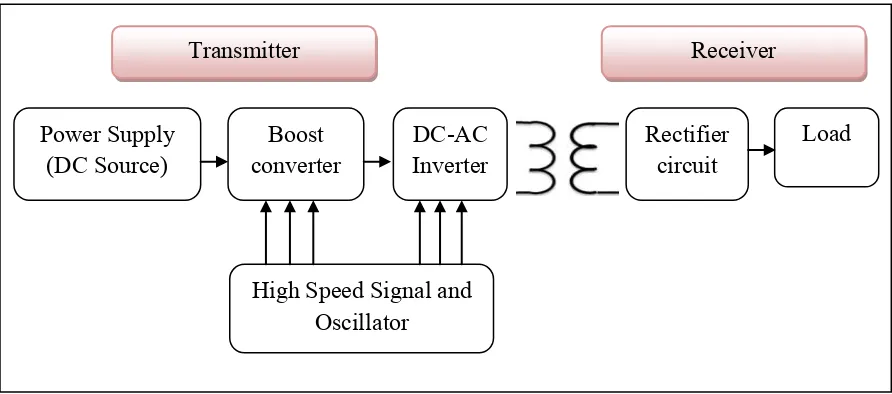
1.4 Scope of project
Figure 1.2: The block diagram of the project
By referring the Figure 1.2, it is shows the block diagram of the project. In this project, the IPT system for charger will be developed where the system consists of designing the transmitter and receiver circuit. In this project, the power can transferred from transmitter to receiver with an air gap of 0.5cm to 3.5cm. Since there are many issues about inductive power transfer device, so, this project just focus on the following properties below:
i. Primary supply - DC power supply or solar panel will generates the voltage direct current 7V-9V. Then the power supply will connected to the boost converters which have increase the voltage direct current around 15V to 20V. The MOSFET that used is IRF510 and it is drive by high speed and oscillator that will produce 1MHz of frequency.
ii. The development of inverter is by using class E power amplifier. The MOSFET that used is IRF530 and it must produce 50% duty cycle of frequency. The MOSFET is drive by high speed and oscillator that will produce 1MHz of frequency. The simulation is used for analysis the outcome expected result and to control the signal for inverter circuit.
Power Supply
(DC Source) converter Boost DC-AC Inverter Rectifier circuit Load
High Speed Signal and Oscillator
5 iii. The number turns of coil is identifying to transmit power from primary coil to
secondary coil.
iv. For the secondary part is the output part. The output is connected to the rectifier circuit to produce the output of the project. The output in this project is in Direct Current (DC).
1.5 Report Structure
6
CHAPTER 2
LITERATURE REVIEW
2.1 Overview
This chapter contains of the literature review on past research and the theoretical concepts applied in this project. It contains the collection information of the project in order to complete the whole project. The literature will focus on the comparison between few paper of journal that are focus on the advantages and disadvantages, efficiency and the application of developing in this IPT systems.
2.2 IPT System
2.2.1 Basic Concept of IPT System